


< Back to Performance Development
By Johnny Liu, CEO at Dowway Vehicle | Published: February 27, 2026
Author’s Note: I’ve spent over a decade working in vehicle design at Dowway Vehicle. I’ve seen firsthand how a car’s structural integrity directly controls its safety and performance. This guide breaks down the core principles, workflows, and real-world uses of Computer-Aided Engineering (CAE) strength analysis. It offers a practical roadmap for engineers who want to build lighter, safer, and more cost-efficient cars without losing structural quality.
- 🚀 Key Takeaways
- 2.1 Core Operating Principles
- 2.2 Foundational Theoretical Support
- 2.3 Strength Evaluation Criteria
- 3.1 Pre-processing: The Core of Simulation Accuracy
- 3.2 Solving and Computation: Deriving Mechanical Responses
- 3.3 Post-processing: Results Analysis and Optimization
- 4.1 General-Purpose FEA Software
- 4.2 Specialized Automotive CAE Software
- 5.1 Case Study 1: Automotive Wheel Hub Static and Impact Analysis
- 5.2 Case Study 2: Vehicle Body Static Strength Analysis
- 5.3 Case Study 3: EV Battery Pack Side Impact Analysis
- 6.1 Core Technical Challenges
- 6.2 Directions for Future Development
- Q1: What CAE methods should be used for automotive structural strength analysis?
- Q2: How do I model loads and boundary conditions accurately?
- Q3: How to decide on mesh density and element types?
- Q4: How do you add fatigue and durability to a CAE strength test?
- Q5: What structural components need special CAE attention?
🚀 Key Takeaways
- Core Role: CAE strength analysis replaces traditional physical testing with a “Design-Simulation-Optimization-Verification” loop. It drastically reduces R&D cycles and costs.
- Fundamental Theory: Driven by the Finite Element Method (FEM) and mechanical equilibrium equations, it tests how structures react to static, dynamic, and extreme loads.
- Key Workflows: Success depends heavily on strict pre-processing (keeping mesh distortion $\le 5\%$), picking the right solver, and applying practical post-processing fixes.
- Industry Software: Teams rely on a mix of general-purpose tools (Abaqus, ANSYS, HyperWorks) and specialized software (LS-DYNA, AVL EXCITE).
- Future Trends: The rise of New Energy Vehicles (NEVs), paired with AI-driven meshing and Digital Twin technology, is changing how we validate vehicle structures.
1. Introduction to Automotive CAE Strength Analysis
Car makers are constantly pushing for lighter, faster, and safer vehicles. CAE strength analysis now sits at the center of the R&D process, covering everything from single parts to full-car tests.
Vehicle strength determines passenger safety and how long the car lasts. Old methods relied heavily on building physical prototypes. That approach took too much time, cost too much money, and slowed down design changes. We simply cannot rely on it anymore.
CAE uses the Finite Element Method (FEM) to run computer simulations. It shows how car parts react to different weights, bending, and stress. Engineers can spot weak spots early and fix the design without building a real part first. Now, CAE works hand-in-hand with CAD design and physical testing to form a closed loop: Design, Simulate, Optimize, and Verify.
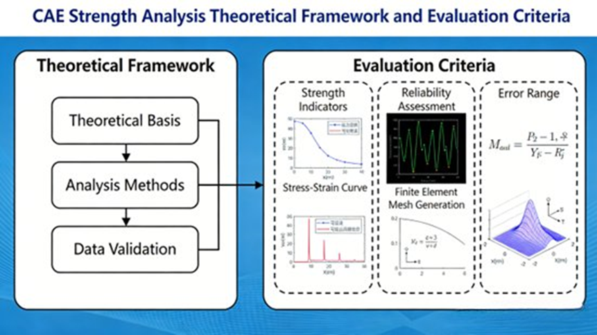
2. Core Principles and Foundational Theories
2.1 Core Operating Principles
To run a CAE strength analysis, you first break down a complex vehicle structure into a finite number of interconnected elements. We call this the finite element model. By solving the mechanical equilibrium equations for these elements, engineers calculate stress, strain, and displacement. The process follows four clear steps: Discretization – Modeling – Solving – Post-processing.
Vehicles handle many different loads every day. These include static loads (the car’s weight, cargo), dynamic loads (hitting a pothole, hard braking), alternating loads (engine vibration, steering), and extreme loads (crashes, rollovers). CAE must accurately simulate these conditions to match real-world driving.
2.2 Foundational Theoretical Support
The science behind CAE strength analysis mixes FEM with mechanics of materials and structural mechanics:
- Finite Element Discretization Theory: Engineers break continuous structures down into tiny shapes (like tetrahedrons or hexahedrons) connected by nodes.
- Material Constitutive Relations: The software needs exact material properties to work. For instance, you must enter the elastic modulus, Poisson’s ratio, and yield strength. For non-linear analysis, you also have to factor in plasticity.
- Mechanical Equilibrium Equations: Based on elasticity rules, the global mechanical equilibrium equation looks like this: $[K]\{u\}=\{F\}$. Here, $[K]$ is the global stiffness matrix, $\{u\}$ is the nodal displacement vector, and $\{F\}$ is the nodal load vector.
- Boundary Conditions and Loads: You must precisely define boundary constraints (fixed or hinged) and load types so the simulation acts like the real environment.
2.3 Strength Evaluation Criteria
- Static Strength: The maximum stress must stay below the allowable stress (Yield Strength / Safety Factor). Safety factors usually sit between 1.2 and 2.5. Maximum displacement must also stay within design limits.
- Dynamic Strength: This accounts for time effects using dynamic strength theories and predicts fatigue life under repeating loads.
- Extreme Strength: During crashes or rollovers, the structure must hold together to protect passengers. We measure maximum deformation, stress peaks, and energy absorption.
3. Key Technical Workflow in Automotive CAE
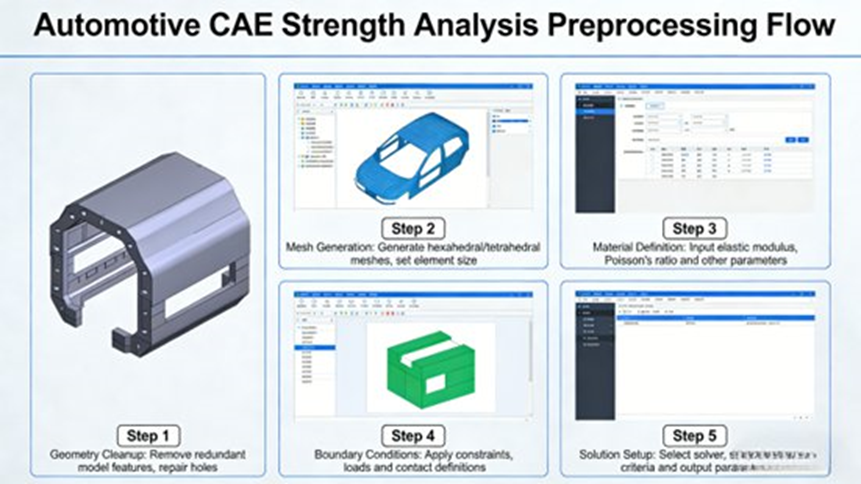
3.1 Pre-processing: The Core of Simulation Accuracy
Engineers spend 60% to 70% of their time on pre-processing. This step turns CAD models into finite element models the software can actually solve.
- CAD Simplification: We remove tiny details like small fillets or holes. For instance, when analyzing a wheel hub, we ignore micro-grooves but keep the core load-bearing spokes.
- Meshing: A bad mesh ruins the results. We use shell elements for car bodies, solid elements for chassis parts, and beam elements for slender components. Strict quality checks keep the mesh distortion rate at or below 5%, the element passing rate at 95% or higher, and the Jacobian determinant at 0.7 or greater.
- Material Parameter Assignment: Precision matters. For example, 6061-T6 aluminum alloy requires exactly 310MPa tensile strength, 276MPa yield strength, and a 69GPa elastic modulus.
- Boundary Conditions & Loads: We apply constraints and loads based on real data. In a frontal crash simulation, we apply specific impact loads required by safety laws.
3.2 Solving and Computation: Deriving Mechanical Responses
The CAE solver calculates the math.
- Direct Solvers run fast and deliver high accuracy for simple static tests.
- Iterative Solvers balance accuracy and speed for complex shapes or dynamic tests.
For non-linear analysis, the computer calculates the math in small, repeating steps to ensure accuracy. Crash simulations often use millisecond-level time steps to catch rapid changes.
3.3 Post-processing: Results Analysis and Optimization
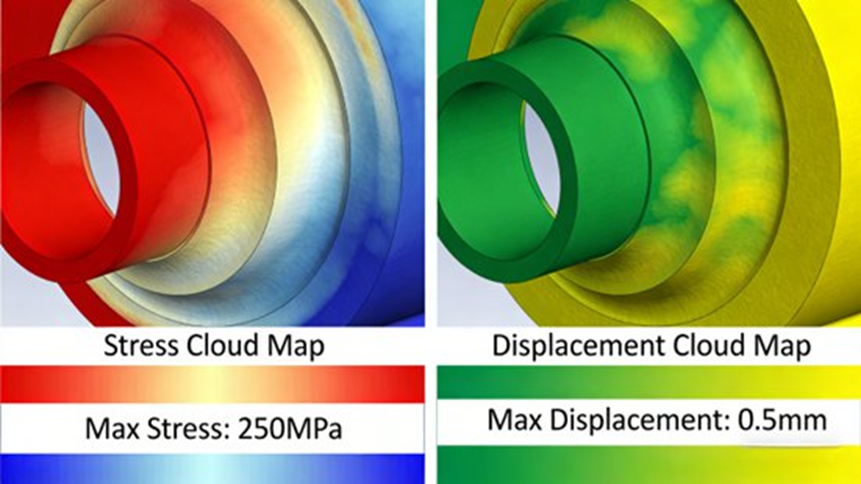
- Visualization: Color-coded contour maps display stress, strain, and displacement.
- Verification: We compare maximum stresses against allowable limits to check if the part passes or fails.
- Optimization Output: We create specific fixes, such as making a section thicker, adding reinforcing ribs, or changing the material.
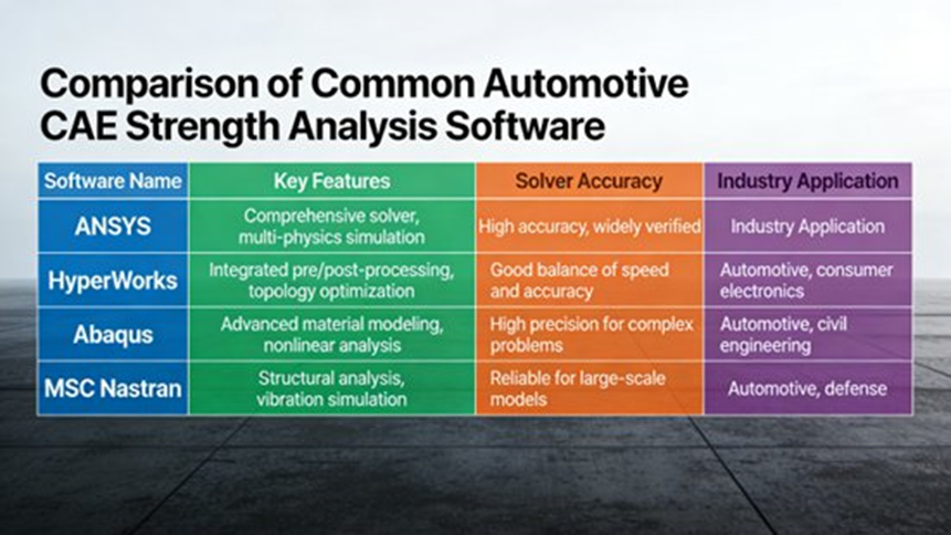
4. Common Simulation Software for Automotive CAE
4.1 General-Purpose FEA Software
- Abaqus: Known for handling heavy non-linear strength tasks like crashes, plastic deformation, and part contact. It supports many different material models.
- ANSYS: Works very well with CAD software. It easily handles multi-physics tests (like mixing heat and structure stress) as well as static, dynamic, and fatigue tests.
- HyperWorks: A top choice for structural optimization. Teams use its powerful meshing tools to drop vehicle weight without losing strength.
4.2 Specialized Automotive CAE Software
- LS-DYNA: The standard choice for extreme dynamic events. It simulates crashes and heavy impacts with incredibly fast solving speeds.
- AVL EXCITE: Built specifically for powertrains. It accurately predicts the fatigue life of engines and transmissions.
5. Real-World Engineering Application Cases
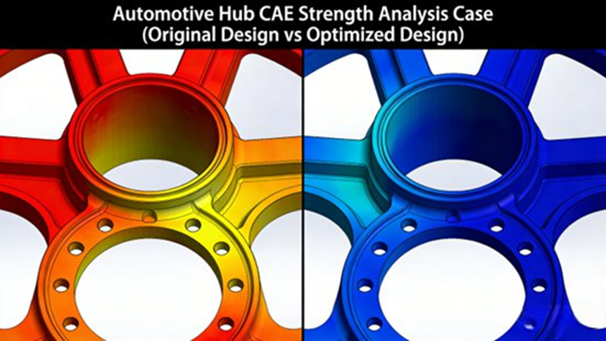
5.1 Case Study 1: Automotive Wheel Hub Static and Impact Analysis
- Goal: Test a 6061-T6 aluminum wheel hub under uniform driving (8000N) and heavy impact (12000N for 0.1s).
- Results: Under normal driving, the maximum stress reached 180MPa (safe). However, the impact test pushed the stress to 290MPa at the spoke roots, pushing past the yield strength.
- Fix: We increased the transition fillet from R3mm to R6mm and thickened the spoke root from 8mm to 10mm. Impact stress dropped 22% down to 230MPa. This fix added only 0.3kg (3.7%) in weight, hitting a perfect balance between strength and light design.
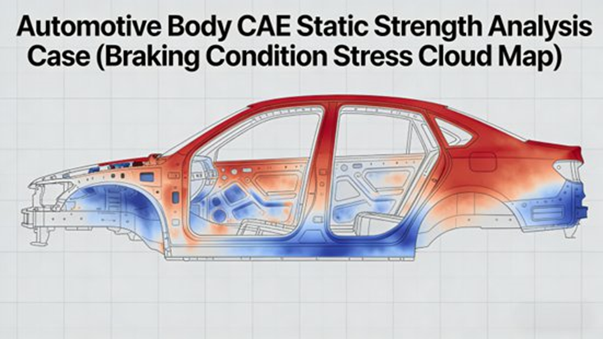
5.2 Case Study 2: Vehicle Body Static Strength Analysis
- Goal: Test a sedan body under a full load, hard braking ($8m/s^2$), and sharp cornering ($6m/s^2$).
- Results: The full-load test (210MPa) and cornering test (250MPa) stayed within safe limits. But braking created a dangerous 290MPa stress point at the front longitudinal beam.
- Fix: We welded a 2mm reinforcement plate to the front beam and tweaked its shape. The maximum stress dropped safely to 240MPa.
5.3 Case Study 3: EV Battery Pack Side Impact Analysis
- Goal: Ensure a New Energy Vehicle (NEV) battery pack does not break open during a side impact (traveling at 5m/s with a 100kg mass).
- Results: The first LS-DYNA simulation revealed a dangerous 320MPa stress on the side casing. This meant the battery could easily rupture (the limit was 287.5MPa).
- Fix: We added reinforcing ribs and internal buffer layers to absorb the hit. The second test confirmed the stress dropped to 230MPa, passing national safety standards easily.
6. Technical Challenges and Future Directions
6.1 Core Technical Challenges
- Simplification vs. Accuracy: Simplifying complex joints (like welds) too much ruins the data. Keeping too many details slows the computer to a crawl.
- Material Accuracy: It is hard to measure the exact non-linear and dynamic properties of certain materials, especially advanced composites.
- Real-World Loads: Copying exact road bumps or unpredictable car crashes in a digital space remains tough.
- Multi-Physics: Testing how mechanical stress, heat, and fluid pressure affect a part all at the same time requires highly complex models.
6.2 Directions for Future Development
- Smart Pre-processing: AI tools are starting to generate meshes and check quality automatically.
- Better Material Databases: Industry databases are using AI to predict material behavior, which cuts down on expensive lab tests.
- Precise Load Data: Engineers are feeding real road test data directly into their simulation models.
- Digital Twins: Teams are linking physical prototypes with virtual models to track stress in real-time.
- Smarter Lightweighting: New optimization techniques help cars shed weight faster while safely adopting composite materials.
7. Frequently Asked Questions (FAQ)
Here are the most common questions engineers ask on forums (like ANSYS and Abaqus communities) about automotive CAE strength analysis.
Q1: What CAE methods should be used for automotive structural strength analysis?
Context: Engineers often debate whether to use Implicit, Explicit, or hybrid finite element approaches.
- Implicit FEA: Used for quasi-static strength analysis. It works very well for linear and mildly nonlinear problems.
- Explicit FEA: Handles highly nonlinear events like large bending, material failure, and crashes. Engineers now use it for some “quasi-static” problems if the part bends a lot.
💡 Tip: Match your solver to the load type. Use explicit solvers when dealing with heavy crashes or severe part contact. Use implicit solvers when the load stays smooth and predictable.
Q2: How do I model loads and boundary conditions accurately?
Context: Copying real road loads or suspension movement in FEA can be tricky.
- Base your loads on real test data or established vehicle load charts.
- For fatigue testing, always use real-world road data or measured strain data.
🏆 Best Practice: Work backward from actual strain measurements. Apply constraints consistently so you do not accidentally create fake stiff areas in your model.
Q3: How to decide on mesh density and element types?
Context: Setting up the mesh is one of the biggest hurdles for new FEA users.
- Build tight, structured meshes in high-stress areas like fillets and welds.
- Use shell elements for thin metal sheets, and solid elements for thick or chunky parts.
📏 Rule of Thumb: Focus on element quality (checking aspect ratio and distortion) rather than just pushing for a higher element count. High quality beats high numbers.
Q4: How do you add fatigue and durability to a CAE strength test?
After finding the stress distribution through a static analysis, engineers use fatigue life prediction methods. This usually involves Rainflow counting and Miner’s rule, matched with S-N curves (Stress-Number of cycles) specific to the metal and welds.
Q5: What structural components need special CAE attention?
- Vehicle Frame & Body in White (BIW): You have to test torsional rigidity with very careful contact rules between welded joints.
- Suspension & Control Arms: Pay close attention to local bending and fatigue life. Engineers almost always validate these parts alongside physical bench tests.
- Brackets & Battery Supports: Check local stress points and mounting interfaces under strictly validated boundary conditions.
8. Final Thoughts
Built on finite element theory, automotive CAE strength analysis serves as the backbone of modern vehicle design. By using software like Abaqus, ANSYS, and LS-DYNA, engineers easily locate structural weak spots and fix them early. The results speak for themselves, as shown in the wheel hub, body frame, and battery pack examples above.
As the car industry shifts entirely toward New Energy, smarter tech, and lighter frames, CAE will adapt. Engineers will focus more on testing battery packs and electric motors under extreme stress. Deep integration with Big Data and Digital Twins will eventually move the industry to a system where virtual simulations lead the design, and physical tests just confirm the math.
