


< Back to Performance Development
Author: Johnny Liu, CEO at Dowway Vehicle
Published: February 28, 2026
Category: Automotive Engineering & CAE Simulation
- Key Takeaways
- 2.1 Understanding Stiffness Analysis
- 2.2 Understanding Modal Analysis
- 2.3 The Theoretical Basis in Structural Dynamics
- 3.1 Pre-processing: The Core Setup (60%-70% of workload)
- 3.2 The Solving Phase
- 3.3 Post-processing and Evaluation
- 4.1 Body-in-White (BIW) Optimization
- 4.2 Car Door Structure Optimization
- 4.3 Vehicle NVH Enhancement
- 4.4 Suspension System Optimization
- 5.1 Why Simulation Differs From Testing
- 5.2 Abnormal Modal Parameters
- 5.3 Solving Non-Convergence
- FAQ Summary
Key Takeaways
- Stiffness Analysis evaluates how well a structure resists bending, ensuring the vehicle carries loads safely and handles well.
- Modal Analysis finds natural vibration patterns to stop structural resonance.
- Both methods rely on Finite Element Analysis (FEA) to skip costly physical prototypes and speed up design.
- Setting up the model correctly—using accurate materials, boundaries, and high-quality meshes—makes up 60-70% of a successful simulation.
1. Introduction to Modal and Stiffness Analysis in Automotive Engineering
Car makers are building lighter, faster, and quieter vehicles. Computer-Aided Engineering (CAE) is now the main tool for structural design and performance testing. Old physical testing takes too long and costs too much. CAE simulation lets engineers find structural flaws early. We call this “simulation-driven design.”
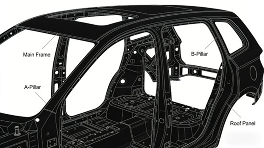
Modal and stiffness analysis form the base of automotive CAE. Stiffness measures how well a structure resists bending or twisting. It affects load capacity, handling, and assembly precision. Modal characteristics are natural dynamic traits. They control how a car vibrates under external loads, like engine rumble or road bumps. These vibrations directly link to vehicle NVH (Noise, Vibration, and Harshness) performance. You cannot design a solid body-in-white (BIW), chassis, door, or suspension without these analyses.
2. Core Concepts and Theoretical Foundation
2.1 Understanding Stiffness Analysis
Stiffness is how well a part resists elastic deformation under a specific load. We measure it in N/m (linear stiffness) or N·m/rad (torsional stiffness). The core rule is that materials stay in the linear elastic stage, following Hooke’s Law ($\sigma=E\epsilon$). Key metrics include:
- Bending Stiffness: Resistance to vertical bending. It makes the vehicle feel “solid” and stops sagging on uneven roads.
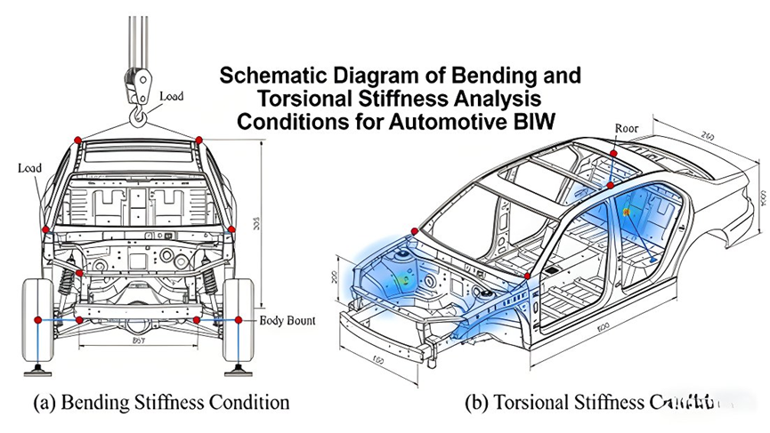
- Torsional Stiffness: Resistance to twisting around the long axis. It keeps handling stable and stops parts from rubbing and squeaking.
- Local Stiffness: The strength at main connection points (like suspension or engine mounts) to transfer loads properly.
2.2 Understanding Modal Analysis
A mode is a natural vibration trait. It depends entirely on mass, stiffness, material, and boundary conditions—not outside forces. Key parameters include:
- Natural Frequency (Hz): The frequency of free vibration without damping. Low-order frequencies (1-200Hz) heavily steer NVH performance.
- Mode Shape: The physical bending pattern at a specific natural frequency, which shows weak resonance areas.
- Damping Ratio: The material’s ability to absorb vibration energy (usually 0.01-0.05 for car structures).
- Analogy: Think of a car body as a guitar string. The natural frequency is the “pitch,” the mode shape is the string’s “form” while vibrating, and the damping ratio is how quickly the sound fades out.
2.3 The Theoretical Basis in Structural Dynamics
- Stiffness Analysis: This relies on statics equilibrium equations:
$$[K]\{u\}=\{F\}$$
where $[K]$ is the stiffness matrix, $\{u\}$ is the displacement vector, and $\{F\}$ is the load vector. - Modal Analysis: This uses structural dynamics equations for undamped free vibration. By assuming harmonic vibration, engineers solve a generalized eigenvalue problem:
$$([K]-\omega^2[M])\{\phi\}=0$$
This equation extracts the structural natural frequencies ($\omega$) and corresponding mode shapes ($\phi$).
3. The Complete FEA Workflow for Modal and Stiffness Analysis
3.1 Pre-processing: The Core Setup (60%-70% of workload)
- Geometric Model Processing: First, you import CAD models (CATIA, UG) to CAE software (HyperWorks, ANSYS). The rule here is simple: keep main structures (like beams and pillars) and remove small details (like tiny holes). This stops meshing errors.
- Finite Element Meshing: Thin sheet structures (doors, BIW) use quadrilateral shell elements (e.g., QUAD4) with distortion rates $\le 15\%$. Thick walls (knuckles) need solid elements, and CWELD elements (usually 6mm diameter) simulate weld points. You pack the mesh tighter (5-10mm) in critical vibration areas.

- Material Properties: Accurate inputs are a must. For steel, Young’s modulus ($E$) is usually 206 GPa and density ($\rho$) is 7850 kg/m³. For aluminum, $E$ is 70 GPa and $\rho$ is 2700 kg/m³. Poisson’s ratio ($\mu$) stays around 0.3.
- Boundary Conditions and Loads: * Modal Analysis: Whole-vehicle runs use “free-free” conditions (no constraints) to pull accurate frequencies.
- Stiffness Analysis: You must copy real-world loads (for example, locking the shock mounts and pushing down vertically for bending tests).
3.2 The Solving Phase
- Stiffness Solving: Static solvers like MSC.NASTRAN SOL101 or OptiStruct handle this part. They use convergence rules to output node displacement and stress.
- Modal Solving: Engineers use eigenvalue extraction methods. The Lanczos method works best for standard models. The AMLS solver (Algebraic Multi-Level Substructuring) speeds up massive computations up to 8 times without losing accuracy.
3.3 Post-processing and Evaluation
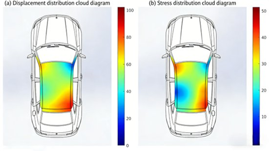
- Stiffness Evaluation: Analysts read maximum displacement and stress contour maps to locate weak spots.
- Modal Evaluation: You compare the extracted natural frequencies against outside noise sources. The design needs at least a 10% frequency gap to avoid resonance.
4. Engineering Applications & Case Studies
4.1 Body-in-White (BIW) Optimization
During the design of a sedan BIW, the first test showed a bending stiffness of 28,000 N/mm and a 1st-order frequency of 25.3 Hz (falling short of the 28 Hz target). Engineers read the results, welded reinforcement plates to the floor, and thickened the rear pillars. The new BIW hit 32,500 N/mm bending stiffness and a 29.7 Hz frequency. They met all goals and only added 3.2 kg of weight.
4.2 Car Door Structure Optimization
A prototype tailgate showed a 1st-order frequency of 22.1 Hz. This sat dangerously close to the engine idle vibration (20-25 Hz). By thickening the inner panel and adding support ribs, the team boosted bending stiffness by 40%. The frequency shifted to 28.6 Hz, completely stopping the resonance and squeaking.
4.3 Vehicle NVH Enhancement
One SUV cabin got too loud while idling (engine vibration hit at 28 Hz). Modal analysis proved the BIW’s 1st-order frequency was 27.8 Hz, causing a massive resonance loop. The team reinforced the front longitudinal beams, pushing the frequency to 32.5 Hz. Idle vibration dropped by 60%, and noise fell by 8 dB(A).
4.4 Suspension System Optimization
A suspension control arm had a 48 Hz natural frequency, matching the exact rumble of a bumpy road (45-50 Hz). Redesigning the arm’s cross-section bumped torsional stiffness by 35% and pushed the frequency to 55 Hz. This change vastly improved handling and ride comfort.
5. Common Issues and Troubleshooting in Analysis
5.1 Why Simulation Differs From Testing
- Causes: Over-simplified shapes, poor mesh quality, or ignoring damping ratios.
- Solutions: Keep main load-bearing geometry, plug in real tested material data, and set accurate damping ratios (0.01-0.05).
5.2 Abnormal Modal Parameters
- Causes: Wrong boundary constraints (too rigid or too loose) or uneven mass distribution.
- Solutions: Default to free-free conditions for whole-vehicle modes. Make sure the digital weight matches the real physical car.
5.3 Solving Non-Convergence
- Causes: Broken mesh elements, parts floating without constraints, or loads causing plastic deformation.
- Solutions: Fix the mesh, double-check static constraints, and verify that the loads stay within the linear elastic limit.
6. Future Trends in Automotive CAE
- Multi-Physics Coupling: Combining heat, magnetic, and structural loads—a must for electric vehicles.
- AI and Machine Learning: AI tools now automate meshing and guess results by matching simulation data with physical tests.
- Synergistic Lightweighting: Merging standard analysis with topology and shape optimization tools to cut weight faster.
- Digital Twin Integration: Feeding live physical car data straight back into the CAE model to adjust parameters on the fly.
7. Wrapping Up
Modal and stiffness analysis sit at the center of car design. By using FEA to test static deformation and dynamic vibration, engineers catch weak points early and stop resonance before parts get built. This strategy slashes development time and cuts costs. As AI and Digital Twins grow, these tools will become even more central to building better, safer cars.
8. Frequently Asked Questions (FAQ)
1. What is modal analysis and why do we need it?
Modal analysis is a structural dynamics test that finds a system’s natural frequencies and mode shapes—the exact ways a part vibrates when disturbed. It uses mass and stiffness properties in an eigenvalue problem to grab these numbers. Resonance happens when outside noise matches a natural frequency. Finding these modes helps engineers stop parts from breaking, leading to safer and quieter structures.
2. How does stiffness relate to modal analysis?
In modal analysis, the stiffness matrix ($[K]$) and mass matrix ($[M]$) control the dynamic behavior. Higher stiffness generally drives up natural frequencies because a stiffer system fights deformation harder under dynamic motion.
3. What is the practical difference between modal analysis and static stiffness analysis?
- Static stiffness analysis calculates exact displacements and stresses under actual physical loads.
- Modal analysis applies zero external loads. It finds free vibration patterns based only on mass and stiffness matrices, predicting inherent vibration traits rather than physical bending.
4. What common issues break a modal analysis and how do you fix them?
Problems usually pop up when engineers define mass sources or constraints incorrectly (like leaving degrees of freedom completely massless or building an unstable model). Fixing boundary conditions and verifying mass distribution usually solves this. Also, modal analysis assumes stiffness stays constant; you cannot run it with frequency-dependent stiffness.
5. How does initial stress or prestress change stiffness and modal results?
For nonlinear structures (like cables pulled tight), prestress changes everything because the dynamic stiffness shifts based on the initial load state. Engineers must run an initial stiffness state that includes applied loads to match real-world conditions.
FAQ Summary
| Question | Key Takeaway |
| What is modal analysis? | Finds natural frequencies & mode shapes to avoid structural resonance. |
| How does stiffness relate to modal analysis? | The stiffness matrix dictates resistance to deformation, directly altering natural frequencies. |
| Modal vs. Static Stiffness | Static calculates load deformations; Modal maps out inherent vibration traits. |
| Common Modal Analysis Issues | Often caused by massless DOFs or bad constraints; fix setup definitions. |
| Prestress Effects | The initial stiffness state heavily alters modes in nonlinear systems. |
