

< Back to Platform Development
By Johnny Liu, CEO at Dowway Vehicle
Published: March 5, 2026
Author’s Note: As the auto industry shifts to electric power, the motor is now the heart of the car. I wrote this guide based on my engineering experience at Dowway Vehicle to break down the exact steps we use to balance performance, reliability, and cost when building modern EV motors.
- Introduction to Automotive Motor Engineering
- Core Principles in Motor Design
- The 8-Step Motor Design and Development Process
- Key Elements of Motor Detailed Design
- Overcoming Technical Challenges
- Future Trends
- Top 5 Frequently Asked Questions About Motor Design & Development
- 1. What are the key steps in the design and development of an electric motor?
- 2. What are the most important parameters considered in motor design?
- 3. What are the biggest challenges in electric motor design and development?
- 4. How do engineers improve the efficiency of electric motors?
- 5. What tools and technologies are commonly used in modern motor development?
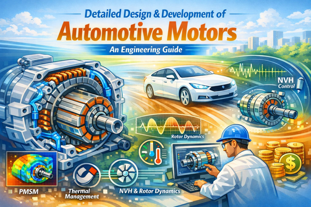
Introduction to Automotive Motor Engineering
Driven by global carbon rules and the shift toward electric vehicles, motors have changed from simple auxiliary parts in gas cars to the absolute core of New Energy Vehicles (NEVs).
Automotive motors must meet much stricter standards than everyday industrial motors. They need a compact size, high power density, superior efficiency, robust reliability, and extreme temperature tolerance (-40°C to 150°C). They must also survive severe vibration and shock while keeping costs low. Ultimately, the design must fit perfectly with the vehicle’s power demands, thermal management system, and control strategies.
Currently, Permanent Magnet Synchronous Motors (PMSM) dominate the market, though alternatives like Synchronous Reluctance Motors (SynRM) and Electrically Excited Synchronous Motors (EESM) are catching up. New tools like hairpin windings, oil cooling, and multi-physics simulation push motor performance forward every year.
Core Principles in Motor Design
You cannot design a motor in a vacuum. It must fit the vehicle’s specific needs. We follow three main rules:
- Vehicle Demand-Driven Strategy: We reverse-engineer the motor from vehicle parameters. For example, a main drive motor for a pure electric passenger car needs high efficiency during high-speed cruising (efficiency ≥93%) and short-term peak power for fast acceleration. Going 0-100km/h in ≤7s requires a peak power 20%-30% higher than the rated power.
- Multi-Disciplinary Synergy: Motor design means balancing electromagnetics (power/efficiency), thermodynamics (cooling), mechanical engineering (vibration/shock resistance), and materials science (power density/lifespan). Over-optimizing just one area will break the whole system.
- Engineering Feasibility: A design must actually work on the assembly line. High power density designs must fit existing manufacturing processes and use stable supply chains. We build in process redundancy to hit a mass production yield rate of ≥99.5%.
The 8-Step Motor Design and Development Process
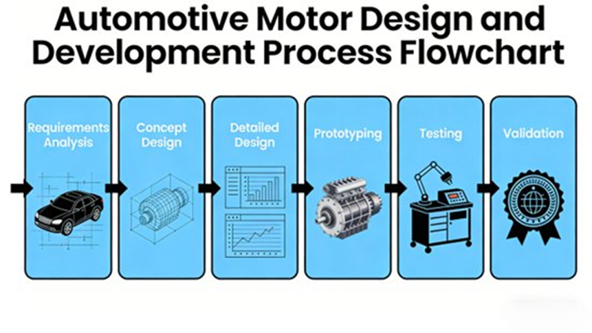
Building an automotive motor is a strict engineering process. We break it down into eight stages:
- Requirements Analysis: We define power limits, efficiency MAPs, environmental needs (vibration per ISO 16750, protection at IP67/IP6K9K), and reliability targets (≥15 years/300,000 km lifespan; failure rate ≤0.1 times/10,000 km).
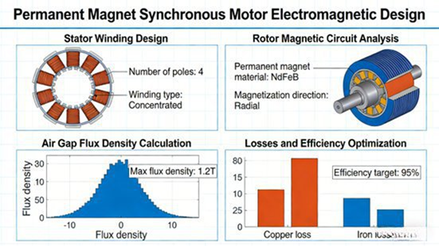
- Concept & Scheme Design: We select the motor topology. A 48-slot/8-pole layout works well for main drives. We prefer hairpin windings because they offer a slot fill factor of ≥75%. For cooling, 50-200kW motors use water, while >200kW motors use oil to keep the temperature rise ≤80K (per GB/T 18488-2015).
- Detailed Design Phase:
- Electromagnetic: We use Ansys Maxwell or JMAG to optimize magnetic fields and cut torque ripple.
- Thermal: CFD simulations refine the cooling system. A 150kW water-cooled motor usually needs a spiral water jacket with a flow rate of 8-10L/min and an inlet/outlet temp difference of 5-8°C.
- Mechanical: We ensure structural safety for peak speeds >15,000 rpm. Shaft spans are set to 4-6 times the shaft diameter to prevent resonance. Rotor dynamic balance hits the G2.5 grade.
- Materials: We use 35WW300 silicon steel for the stator, 38H/42SH NdFeB magnets, copper alloys for windings, and H-class (180°C) insulation.
- Multi-Physics Simulation: We couple electromagnetic, thermal, and structural simulations. NVH tests ensure vibration stays ≤2.5mm/s.
- Prototyping: We build physical models using mass-production standards.
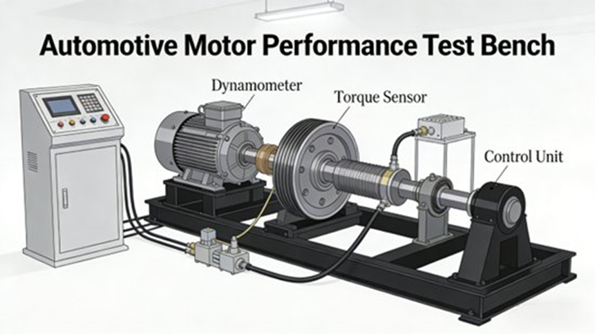
- Bench Testing: The prototypes run on test benches to verify power, torque, and insulation, ensuring peak efficiency is ≥97%.
- Real-Vehicle Calibration: Road testing proves the motor matches the vehicle’s powertrain under extreme weather and driving conditions.
- Mass Production Rollout: We set up strict Quality Control (QC) for stamping, lamination, winding, and magnet assembly.
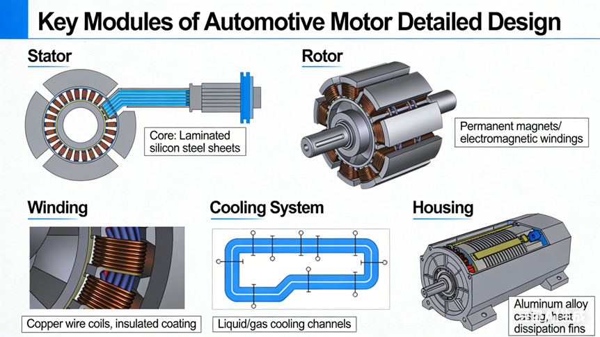
Key Elements of Motor Detailed Design
Depending on the vehicle, we focus our engineering on a few specific areas:
- Electromagnetic Design: We keep air gaps between 0.5-0.8mm. We strictly control torque ripple to within 5%.
- Thermal Management: The motor’s heat systems must sync with the vehicle’s thermostat logic to hold an optimal operating window of 80°C-120°C.
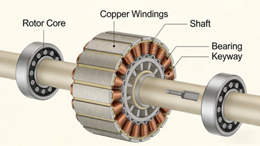
- Mechanical Structure: * Rotors: Interior Permanent Magnet (IPM) rotors use a “V” or “Double-V” magnet layout for extra mechanical strength.
- Shafts: We use high-strength alloys like 40CrNiMoA, tempered so critical speeds sit >1.2 times the peak operational speed.
- Sealing: We rely on fluororubber O-rings and double-lip skeleton oil seals.
- Balancing: Residual unbalance is kept strictly ≤3g·mm.
- Engineering Adaptation: BEVs need a PMSM with a power density of ≥4.5kW/kg. Commercial vehicles often use asynchronous motors to save money, targeting ≥3kW/kg.
Overcoming Technical Challenges
- High-Speed Rotor Reliability ( >20,000 rpm ): Extreme speeds cause centrifugal forces that warp parts. We fix this by using high-strength silicon steel for IPMs, or carbon fiber composite sleeves for Surface Permanent Magnets (SPMs).
- Preventing Demagnetization: High heat and reverse magnetic fields ruin magnets. We choose high-coercivity magnets with added Dysprosium (e.g., 42SH, HcJ≥2000kA/m, Tc≥150°C). We limit field weakening current to -0.3In. We apply Ni-Cu-Ni plating to stop corrosion, and use software derating if temperatures pass 180°C.
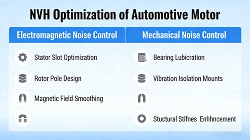
- Mastering NVH Control: High-frequency whining ruins the driving experience. We optimize pole-slot combinations and PWM switching frequencies. We also use low-noise ceramic bearings and add damping materials.
- Cost Management: Volatile rare-earth prices hurt budgets. We look at rare-earth-free SynRM designs and use “X-in-1” integrated powertrain layouts to drop component counts.
Future Trends
The industry is moving fast. We are pushing for higher power densities (targeting ≥6kW/kg) and “Multi-in-1” integration that loops in DC/DC converters and OBCs. Engineers are also testing digital twin lifecycle management and rare-earth-free architectures to cut costs. Adapting to multi-energy systems, like hydrogen fuel cells, will direct the next decade of motor engineering.
Top 5 Frequently Asked Questions About Motor Design & Development
1. What are the key steps in the design and development of an electric motor?
Answer: The process moves from requirement definition through detailed design, simulation, physical prototyping, and final testing.
Engineers follow these structured steps:
- Requirements definition: Determining required torque, speed, efficiency, power rating, voltage, and environmental conditions.
- Motor topology selection: Choosing the right motor type (e.g., induction motor, PMSM, switched reluctance motor).
- Electromagnetic design: Optimizing stator and rotor geometry, winding configuration, and magnetic materials.
- Thermal design: Ensuring adequate cooling to stop overheating.
- Mechanical design: Building shafts, bearings, housing, and structural components.
- Simulation and modeling: Using multi-physics software to check performance.
- Prototype and testing: Building prototypes and testing performance, NVH, and reliability.
2. What are the most important parameters considered in motor design?
Answer: Engineers look closely at torque, speed, efficiency, and thermal limits to ensure the motor fits the vehicle perfectly.
Key parameters include:
- Torque: The rotational force produced by the motor.
- Speed (RPM): The rotational speed required for the application.
- Power output: Calculated from torque and speed.
- Efficiency: The ratio of mechanical output power to electrical input power.
- Power density: The amount of power produced relative to motor size or weight.
- Thermal limits: The maximum operating temperature of windings and magnets.
- Power supply characteristics: Voltage, frequency, and current requirements.
3. What are the biggest challenges in electric motor design and development?
Answer: The main hurdles are managing intense heat, reducing mechanical noise, and balancing high power density with strict mass-production cost limits.
Specific challenges include:
- Increasing power density while maintaining a compact size.
- Improving energy efficiency to reduce battery drain.
- Thermal management to prevent overheating and material degradation.
- Material limitations, especially the supply and cost of rare-earth magnets.
- Noise and vibration (NVH) reduction for smoother operation.
- Balancing efficiency, weight, cost, and manufacturing feasibility in a single design.
4. How do engineers improve the efficiency of electric motors?
Answer: We boost efficiency by reducing core and copper losses, improving fluid cooling, and refining the overall magnetic design.
Methods include:
- Using high-quality magnetic materials (like high-grade silicon steel) to cut core losses.
- Optimizing stator and rotor geometry to improve magnetic flux distribution.
- Reducing copper losses with better winding designs (such as hairpin technology).
- Improving cooling systems (e.g., immersion oil cooling) to hold optimal operating temperatures.
- Using advanced control methods such as efficient Traction Inverters.
- Reducing mechanical friction losses through better bearings and lubrication.
5. What tools and technologies are commonly used in modern motor development?
Answer: Engineers rely heavily on digital simulation software like FEA and CFD to test thousands of designs virtually before building physical models.
Standard tools include:
- Finite Element Analysis (FEA) for electromagnetic field simulation.
- Computational Fluid Dynamics (CFD) for thermal and cooling analysis.
- Multi-physics simulation platforms that combine electromagnetic, thermal, and mechanical models.
- Optimization algorithms to automatically find the best design parameters.
- Rapid prototyping and automated testing systems.
