

< Back to Platform Development
By Johnny Liu, CEO at Dowway Vehicle
Published: March 5, 2026
- 1. Introduction to VCU & ECU in Automotive Electronics
- 2. Core Functions and Hardware Foundation
- 3. VCU & ECU Software Architecture Design
- 4. Key Technologies in Software Design
- 5. The V-Model Engineering Process
- 6. Testing Framework & Practical Solutions
- 7. Compliance Standards and Future Trends
- 8. Frequently Asked Questions
- Bonus: 10 Advanced Interview Questions for VCU/ECU Software Architects
Key Takeaways:
- The Software Shift: Software now makes up over 50% of a modern vehicle’s value.
- Core Controllers: The Vehicle Control Unit (VCU) makes high-level decisions for EVs and PHEVs. Electronic Control Units (ECUs) handle specific subsystem tasks like braking or engine management.
- Engineering Constraints: Automotive software must survive extreme temperatures (-40℃ to 125℃), guarantee millisecond response times, last 10 to 15 years, and meet strict ISO 26262 safety standards.
- Architecture: The industry relies on modular, layered architecture based on AUTOSAR.
1. Introduction to VCU & ECU in Automotive Electronics
Cars are changing fast. Today, software acts as the core differentiator in how a vehicle performs on the road. The Vehicle Control Unit (VCU) and Electronic Control Units (ECUs) sit at the center of this shift.
Unlike standard consumer electronics, automotive software operates under extreme stress. Engineers must build software that guarantees automotive-grade reliability, ignores electromagnetic interference, and maintains absolute safety across millions of driving hours. This guide breaks down the exact hardware limits, software architectures, algorithms, and testing methods needed to build reliable VCU and ECU systems.
2. Core Functions and Hardware Foundation
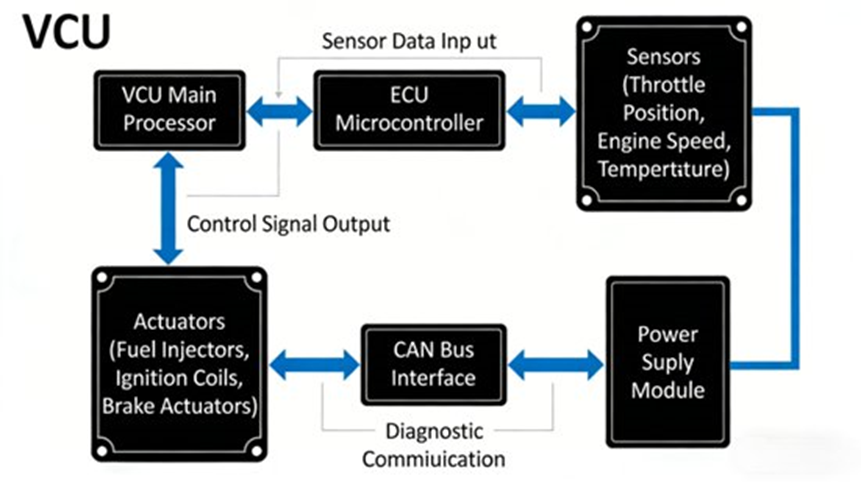
Both units form a continuous closed-loop system: Perception → Decision → Execution → Feedback via in-vehicle networks.
- VCU (Vehicle Control Unit): This is the main brain for New Energy Vehicles (NEVs). It reads driver inputs like the acceleration pedal position. Then, it coordinates the motors, batteries, and chargers to manage power distribution, energy recovery, and safety.
- ECU (Electronic Control Unit): These are the physical executors used in all cars. For example, the Engine Management System (EMS) controls fuel injection, and the Anti-lock Braking System (ABS) tracks wheel speed.
Software design relies heavily on the physical hardware. To pass AEC-Q100 and ASIL (B/D) certifications, engineers follow strict hardware rules:
| Hardware Component | VCU Requirements | ECU Requirements | Key Engineering Specs |
| Microcontroller (MCU) | Multi-core (e.g., NXP S32K3, Infineon AURIX), >100MHz | Mid-to-low end (e.g., STM32, Renesas RH850) | Must support parallel processing. |
| Memory | Flash: >1MB; High-speed RAM | Flash: 256KB – 1MB; High-speed RAM | Flash must keep data after power-off. |
| Interfaces | Analog/Digital I/O, Ethernet, CAN FD | I/O, Relays, LIN, CAN 2.0B | Connects high and low-speed bus protocols. |
| Power Module | 9V–16V tolerance | 9V–16V tolerance | Needs over/under-voltage protection. |
3. VCU & ECU Software Architecture Design
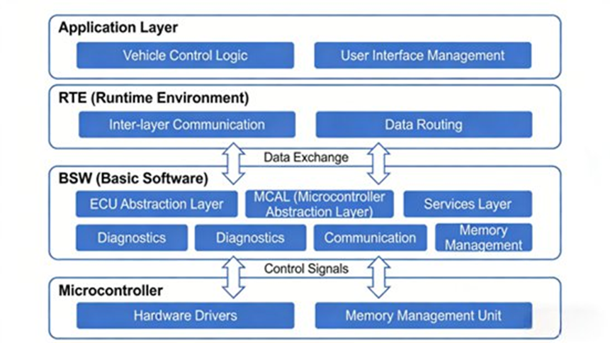
Modern automotive software uses a layered, modular layout based on AUTOSAR (Automotive Open System Architecture). This separates the hardware from the software, letting developers write code once and use it across different chips.
- Hardware Abstraction Layer (HAL / MCAL): The lowest level. It standardizes basic functions (like GPIO initialization or CAN data sending) to hide hardware differences.
- Basic Software Layer (BSW): Provides core services. It holds the Real-Time Operating System (RTOS like FreeRTOS or SYS/BIOS), network stacks, and ISO 14229 diagnostic modules.
- Middleware (MW): Connects the BSW to the applications. It holds common math functions, like Kalman filters to reduce sensor noise, and DBC parsers for CAN signals.
- Application Layer (APP): The top level where specific control functions live. A VCU power allocation module or an ECU fuel injection module sits here.
4. Key Technologies in Software Design
Real-Time Control and RTOS Management
Automotive code cannot wait. A VCU power allocation command must process within 10ms. An ECU braking command needs to happen within 5ms.
The RTOS uses preemptive scheduling to meet these deadlines. Fault-handling tasks get the highest priority. Logging gets the lowest. Interrupt processing times must stay under 1ms. Engineers often use a “Service Routine + Task Queue” method for fast interrupts to prevent the CPU from freezing.
Core Control Algorithms
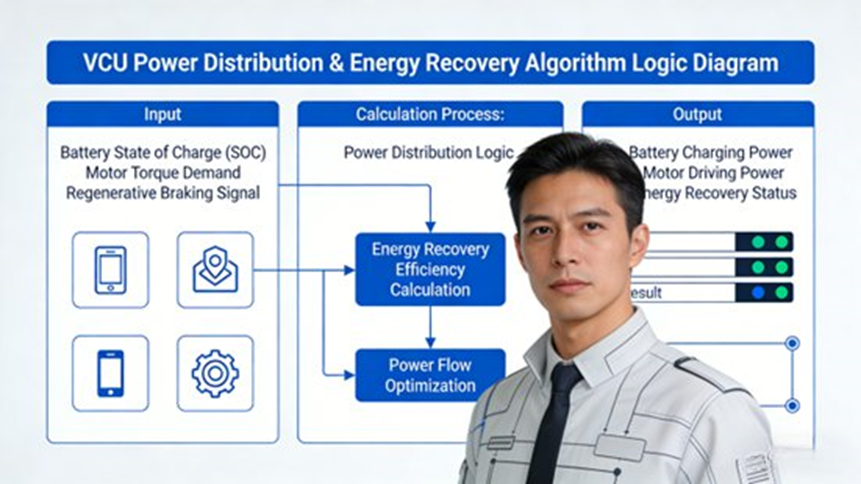
- VCU Logic: The system dynamically balances power between the motor and engine based on the pedal position and battery SOC. For energy recovery, it uses PID control algorithms to turn kinetic energy back into battery charge. The software carefully adjusts the recovery torque so the car still brakes safely.
- ECU Logic: An engine ECU uses closed-loop PID control to manage the air-fuel ratio and adjust ignition timing based on engine RPM.
Bus Communication Protocols
VCUs and ECUs talk over CAN 2.0B, CAN FD, and LIN networks. Engineers define strict signal matrices. For example, a VCU sends a Torque Command to the Motor ECU using ID 0x100, 8 bytes of data, on a 10ms cycle. The Motor ECU replies with Speed Feedback using ID 0x101, 4 bytes of data, on a 5ms cycle.
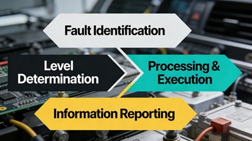
Fault Diagnosis and Safety (ISO 15031-6)
The software constantly checks sensor data against hard limits. If the VCU power supply drops below 9V, it triggers a fault. Faults fall into four levels:
- Level 1 (Emergency): Immediate motor shutdown.
- Level 2 (Severe): Power restriction (Limp-Home mode).
- Level 3 (General): Partial function loss; main driving remains fine.
- Level 4 (Minor): Logged for future maintenance.
The memory must store at least 50 historical faults that survive power cycles.
Functional Safety (ISO 26262)
VCU power modules generally need an ASIL-B safety rating. Critical engine ignition requires ASIL-C. Engineers use dual-core MCUs. The main core runs the logic, while a secondary checker core watches for errors and takes over if the main core fails.
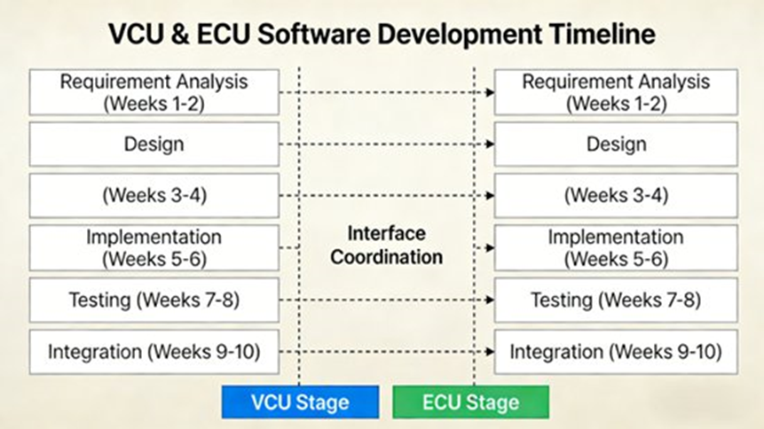
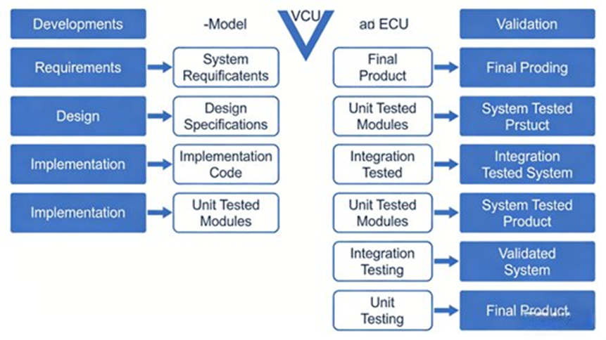
5. The V-Model Engineering Process
Automotive software engineering follows the 8-stage V-Model to track every requirement from start to finish.
- Requirements Analysis: Setting strict targets, like a power allocation error of ≤5%, energy recovery efficiency of ≥20%, and fault response time of ≤10ms.
- System Design: Planning the layered architecture and CAN bus matrix.
- Detailed Design: Setting PID parameters and filtering logic.
- Coding Implementation: Writing C/C++ code strictly under MISRA C standards to prevent bugs.
- Unit Testing: Running static code analysis.
- Integration Testing: Checking bus communication between modules.
- System Testing: Flashing code to actual hardware for HIL (Hardware-in-the-Loop) bench testing.
- Validation & Delivery: Final checks and vehicle integration.
6. Testing Framework & Practical Solutions
Engineers use a multi-step testing framework to catch bugs early:
- Simulation: Using MATLAB/Simulink to test power distribution algorithms visually.
- HIL Testing: Using dSPACE systems to simulate real-world RPM and engine load against the physical ECU.
- Road Testing: Driving the physical car through city traffic, highways, and water.
Solving Common Bottlenecks:
To make software work across multiple car models, engineers use parameterized configuration files instead of rewriting core code. If a CPU gets overloaded, they replace heavy math formulas with simple “Lookup Tables” to save processing time. To trace hidden bugs, they build detailed data-loggers that capture the vehicle’s exact state when an error occurs.
7. Compliance Standards and Future Trends
Engineers must follow a strict set of rules: ISO 26262 for safety, MISRA C/C++ for coding, ISO 11898/14229 for CAN and diagnostics, AEC-Q100 for hardware, and ISO/SAE 21434 to stop hackers.
Looking ahead, the industry is moving from dozens of small ECUs to a few powerful Domain Controllers using a Service-Oriented Architecture (SOA). Teams are adding Deep Learning to predict driver habits. OTA (Over-The-Air) updates now allow differential patching to fix software remotely. Furthermore, the AUTOSAR Adaptive platform uses hypervisors to run multiple operating systems on a single chip.
8. Frequently Asked Questions
Q1: What is the standard software architecture for a VCU or ECU?
Short Answer: The industry relies on a layered, AUTOSAR-compliant architecture to separate hardware from application logic.
Most automotive ECUs use this structure to ensure the code is modular and safe. The layers include the MCAL (Hardware Drivers), BSW (Operating System, CAN stacks, Diagnostics), Middleware (Signal processing), and the Application Layer (Control algorithms).
Q2: How does the VCU coordinate with multiple ECUs in a vehicle?
Short Answer: The VCU acts as the central brain, reading vehicle inputs and sending action commands over CAN and LIN networks to individual ECUs.
Modern cars contain dozens of ECUs. The VCU reads pedal inputs and battery states, computes the right response, and sends data over high-speed networks (like CAN FD or Automotive Ethernet) to specific units like the Motor Control Unit or Braking System.
Q3: How are control algorithms for VCU/ECU developed?
Short Answer: Engineers use Model-Based Development (MBD) to design visual logic models and automatically generate the final C code.
Instead of writing raw C code from scratch, teams use tools like MATLAB and Simulink to map out the logic. They run simulations on these models, and then use tools like TargetLink to build production-ready code for the hardware.
Q4: How is safety ensured in ECU and VCU software?
Short Answer: Engineers strictly follow ISO 26262 standards, using hardware redundancy and continuous software checks to prevent dangerous failures.
Systems receive ASIL ratings based on risk. Engineers use dual-core lockstep CPUs, watchdog timers, and CRC data verification. They run fault-injection tests to prove that a single wire break or sensor failure will not cause a crash.
Q5: How can engineers manage complexity in large ECU systems?
Short Answer: They use modular design and move toward Service-Oriented Architecture (SOA) to keep software functions independent.
Because 85% of vehicle features depend on other features, tightly coupled code breaks easily. By using Automotive Ethernet and SOA, engineers separate functions. This means they can update one module over the air without breaking the rest of the car’s network.
Bonus: 10 Advanced Interview Questions for VCU/ECU Software Architects
(Test your knowledge with these questions frequently asked by top OEMs and Tier-1 suppliers).
- How do you resolve a priority inversion problem in an OSEK/AUTOSAR operating system?
- Explain the exact sequence of a CAN bus waking up an ECU from a deep sleep state.
- How do you design a graceful Limp-Home strategy for a VCU when the primary torque sensor fails?
- In Model-Based Development, how do you handle floating-point to fixed-point conversion for a low-end MCU?
- What is the functional difference between ASIL decomposition and physical hardware redundancy?
- How do you ensure data consistency when multiple fast-cycle tasks read from the same global variable?
- Explain the UDS (ISO 14229) 0x19 service and how the EEPROM stores historical DTCs and freeze frames.
- How would you implement an A/B partition swap strategy for a secure OTA update on a VCU?
- What are the technical trade-offs between CAN 2.0B, CAN FD, and Automotive Ethernet in powertrain controls?
- Describe how you use the AUTOSAR RTE layer to detach a new energy recovery algorithm from the underlying hardware.
