

< Back to Platform Development
Author: Johnny Liu, CEO at Dowway Vehicle
Published: March 5, 2026
Category: Automotive Engineering / Hardware Development
- 1. VCU Hardware Engineering Basics
- 2. Core Requirements and Design Principles
- 3. VCU Hardware Architecture Design (The 4-Layer Model)
- 4. Key Component Selection and PCB Design
- 5. The V-Model Development Process
- 6. Common Challenges and Troubleshooting
- 7. Final Thoughts and Future Outlook
- 8. Frequently Asked Questions (FAQ)
- Q1: What is the role of a VCU in an electric or hybrid vehicle?
- Q2: What are the main hardware components of a VCU controller?
- Q3: What safety standards must VCU hardware meet?
- Q4: What communication networks are typically used in VCU hardware?
- Q5: What is the typical development process for VCU hardware and software?
Key Takeaways for Automotive Engineers:
- Core Role: The VCU (Vehicle Control Unit) operates as the powertrain brain of New Energy Vehicles (NEVs), coordinating the BMS, MCU, and BCM.
- Standards: Hardware must strictly comply with ISO 26262 (Functional Safety) and GB/T 18655 (EMC).
- Architecture: Uses a 4-layer model (Core Control, Signal Interaction, Power Management, and Safety Protection).
- Development Process: Follows the Automotive V-Model, progressing from requirements (e.g., ≤500 RMB cost target) to lab and vehicle testing.
1. VCU Hardware Engineering Basics
New energy vehicles (NEVs) require highly integrated and safe systems. The Vehicle Control Unit (VCU) serves as the central brain of the vehicle’s powertrain. The hardware platform must run stably in complex engineering scenarios. The VCU handles multi-node communication with the Battery Management System (BMS), Motor Control Unit (MCU), and Body Control Module (BCM). It also collects accelerator and brake pedal signals, calculates torque, and runs real-time fault diagnostics.
Unlike standard industrial controllers, automotive VCUs operate in harsh environments. They endure extreme temperatures (-40°C to 105°C), severe vibration, electromagnetic interference (EMC), and voltage fluctuations. Because of this, hardware engineers must strictly follow automotive industry standards, such as ISO 26262 for functional safety and GB/T 18655 for electromagnetic compatibility. The goal is to balance hardware reliability with mass-production feasibility.
2. Core Requirements and Design Principles
2.1 Essential Functional Requirements
Based on actual automotive engineering, VCU hardware must support these specific functions:
- Signal Acquisition: Collects analog (pedal travel, coolant temp), digital (gear, key, fault signals), and frequency data (vehicle/motor speed). Precision must meet ±1% with a response time of ≤10ms, backed by strong signal filtering.
- Communication Interfaces: Supports CAN 2.0B (up to 1Mbps), CAN FD (up to 2Mbps data rate), and LIN bus. Used for real-time data exchange with the BMS, MCU, and chargers. The communication bit error rate must remain ≤10⁻⁸.
- Actuator Drive Control: Multi-channel high/low-side power drivers support PWM output (100Hz–10kHz, ±1% duty cycle accuracy). These outputs drive water pumps, vacuum pumps, and cooling fans. The design requires built-in overcurrent, overtemperature, and short-circuit protection.
- Safety and Protection: Follows ISO 26262 ASIL-B to ASIL-D. Features include a hardware watchdog, power monitoring, reset protection, and High-Voltage Interlock (HVIL). These mechanisms guarantee the vehicle enters a safe state (e.g., limp-home mode) during critical hardware failures.
- Diagnostics and Calibration: Supports On-Board Diagnostics (OBD) and offline calibration. Engineers use this to monitor hardware status and adjust control parameters.
2.2 Fundamental Hardware Design Principles
- Reliability First: Use AEC-Q100/AEC-Q200 certified components. Apply redundancy (dual-core lockstep MCUs, dual-channel signal acquisition) to guarantee a stable lifecycle of ≥15 years or 200,000 kilometers.
- Real-Time Performance: Optimize the PCB layout to shorten signal transmission paths. Select high-performance MCUs for millisecond-level computing.
- Safety Compliance: Run Fault Tree Analysis (FTA) and Design Failure Mode and Effects Analysis (DFMEA) to locate and stop potential failure points.
- Mass Production Feasibility: Standardize interfaces and use modular designs to control costs and simplify manufacturing.
3. VCU Hardware Architecture Design (The 4-Layer Model)
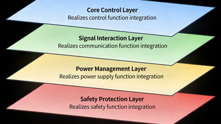
The VCU hardware relies on a modular 4-layer architecture: Core Control, Signal Interaction, Power Management, and Safety Protection.
3.1 Core Control Layer
This is the computing heart of the unit.
- MCU: Requires a 32-bit automotive-grade chip. Dual-core lockstep structures meeting ASIL ratings work best (e.g., Infineon AURIX TC3xx for ASIL-D, NXP S32K or STM32H7 for ASIL-B). Clock speeds reach up to 480MHz. For example, a hybrid VCU uses an AURIX TC375 MCU to run redundant torque calculations.
- Memory: A Flash and RAM combination. 16MB–64MB automotive-grade Flash stores programs and calibration data. 1MB–4MB RAM holds real-time calculation variables.
- Clock and Reset: An external crystal (8MHz or 16MHz) paired with an internal PLL delivers ±0.1% accuracy. Reset circuits combine power-on, manual, and watchdog resets to prevent system freezes.
3.2 Signal Interaction Layer
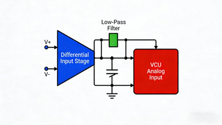
- Analog Input: Uses differential inputs with instrumentation amplifiers (e.g., INA128) and low-pass filters. Requires 12-16 bit ADCs, ≥100Hz sampling, 0-5V or 0-12V input range, and overvoltage protection via TVS diodes.
- Digital I/O and Frequency: Digital inputs use optocouplers (e.g., TLP181) for electrical isolation. Outputs rely on MOS transistors. Frequency inputs use Schmitt triggers (e.g., 74HC14) for 10Hz–10kHz ranges (±0.5% accuracy).
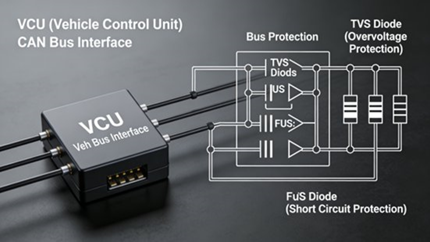
- Communication Modules: Uses automotive transceivers (TJA1050/MCP2515 for CAN 2.0B, TJA1057 for CAN FD, TJA1020 for LIN at 9.6-19.2kbps). Includes TVS and PTC self-recovery fuses to protect the bus from short circuits.
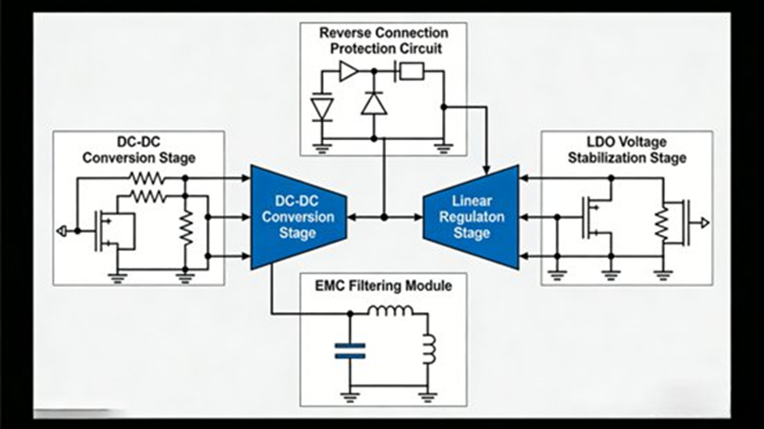
3.3 Power Management Layer
Vehicle power fluctuates constantly. Voltage can drop below 9V during engine start-up and surge above 16V during regenerative braking.
- Two-Stage Supply: Stage 1 uses a DC-DC converter (e.g., TI TPS54331) to step down 12V/24V to 5V. Stage 2 uses an LDO regulator (e.g., TI LM1117) to drop 5V down to 3.3V for digital circuits. This secures a wide 9V–36V input range with ±1% output precision.
- Protection: Incorporates diode/MOS-based reverse connection protection and EMC filtering using common mode chokes and capacitors.
3.4 Safety Protection Layer
- Hardware Watchdog: Independent chips (e.g., ST M95080) reset the MCU if the software stops responding.
- Power Monitoring: Voltage supervisors (e.g., TI TPS3808) trigger system alarms if the voltage crosses safe thresholds.
- High-Voltage Interlock (HVIL): Cuts high-voltage output instantly if a circuit breaks or cable insulation fails.
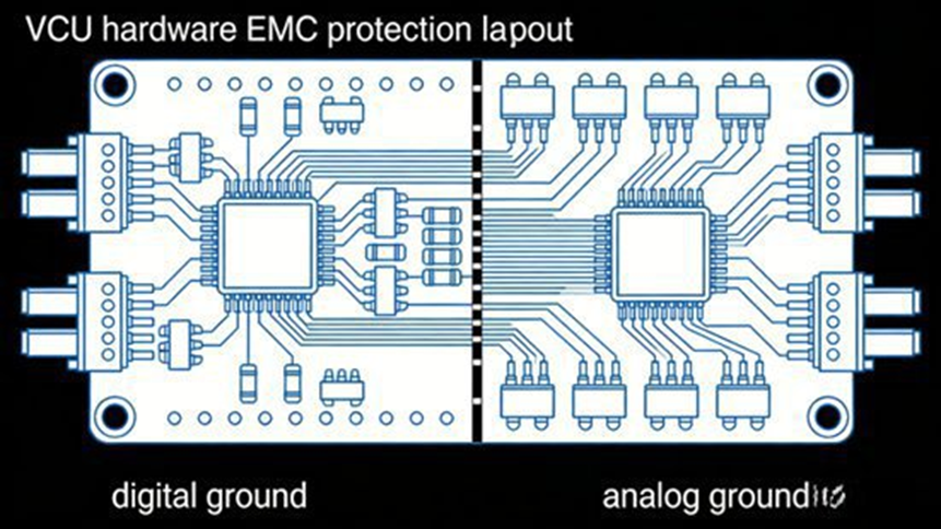
- EMC Protection Layout: Physically separates analog and digital grounds on the board. This achieves GB/T 18655 Level III immunity (radiated emissions ≤60 dBμV/m).
4. Key Component Selection and PCB Design
4.1 Automotive-Grade Component Selection
- MCU: NXP S32K344 (ASIL-B, 160MHz, 8MB Flash, 1MB RAM) fits passenger EVs perfectly. Infineon AURIX TC397 (ASIL-D, 300MHz, 32MB Flash, 4MB RAM) fits hybrid commercial vehicles. The MCU needs ≥16 ADC channels and ≥2 CAN interfaces.
- Power ICs: DC-DC conversion efficiency must reach ≥90%. LDO ripple rejection needs to be ≥60dB.
- Signal Components: Choose amplifiers with CMRR ≥80dB, optocouplers with ≥2500V isolation voltage, and MOS transistors with low on-resistance.
4.2 PCB Design Rules
- Layout and Routing: Keep analog and digital zones separate. Apply single-point grounding at the power module. Make power traces ≥1mm wide and signal traces ≥0.2mm (spaced ≥2mm apart). High-speed signals need 50Ω/120Ω impedance matching (length ≤10cm). Analog differential traces require equal lengths and ≤0.5mm spacing.
- Thermal Management: Heat dissipation pads must be at least twice the component package area. Mount heat sinks to high-heat devices to keep maximum operating temperatures ≤85°C.
- Protection: Use a 1.6mm board thickness to resist road vibration. Apply full solder mask coverage and design fool-proof physical connectors.
4.3 Redundancy Design
Engineers remove single points of failure to meet functional safety standards:
- MCU: Dual-core lockstep checking.
- Signals: Dual-channel data acquisition for throttle pedals and HVIL.
- Power/Comm: Main and backup power supplies, paired with dual-bus CAN networks.
5. The V-Model Development Process
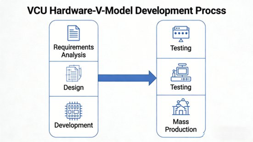
VCU hardware follows the strict automotive V-Model development cycle.
- 5.1 Requirements Analysis: Define hardware metrics based on specific vehicle specs. Example target: A passenger EV VCU needs an IP40 protection rating and a per-unit cost under 500 RMB.
- 5.2 Hardware Design Phase: Draw EDA schematics (Altium/Cadence), run Multisim simulations, perform SI/EMC PCB analysis, and output the final BOM.
- 5.3 Prototyping and Debugging: Apply SMT soldering to the prototype. Test voltage ripples, ADC precision, CAN error rates, and verify watchdog/HVIL triggers.
- 5.4 Testing and Validation: * Lab Tests: GB/T 2423 (-40°C to 105°C for 2h, cyclic damp heat, Q/CT 413 vibration, 16h neutral salt spray); GB/T 18655 (EMC); ISO 26262 fault injection.
- Vehicle Tests: Dynamic torque control, limp-home fault simulation, and multi-terrain road adaptation.
- 5.5 Mass Production Preparation: Optimize SMT processes, lock in supplier agreements, apply ISO 9001 quality controls, and build end-of-line production testing fixtures.
6. Common Challenges and Troubleshooting
- Analog Signal Interference: Solution: Use differential inputs, low-pass filters, single-point grounding, and increase ADC sampling rates using mean filtering.
- Power Supply Ripple or Instability: Solution: Install high-efficiency DC-DC + LDOs, add electrolytic/ceramic capacitors, shorten power traces, and place precise TVS diodes.
- Thermal Management Issues: Solution: Expand heat pads, mount heat sinks on DC-DC/MOSFETs, and separate high-heat components from the main MCU.
- Mass Production Inconsistency: Solution: Standardize SMT parameters, apply strict incoming quality control (IQC) for chips, and run 100% functional testing before shipping.
- EMC Test Failures: Solution: Separate digital and analog grounds, match high-speed impedances, insert common mode chokes, use shielded cables, and adjust the metal enclosure design.
7. Final Thoughts and Future Outlook
7.1 Hardware Engineering Realities
Developing VCU hardware is a strict and exact engineering task. By following the V-Model process, designing redundancy, selecting the right AEC-Q100 components, and testing rigorously, engineers deliver the hardware foundation required for EV powertrain control.
7.2 Future Outlook
- High Integration: Domain Controllers will merge VCU, BCM, and ADAS functions to reduce the total ECU count.
- High Computing Power: Multi-core MCUs (e.g., AURIX TC4xx, NXP S32G) will run complex AI algorithms directly on the board.
- Safety: ASIL-D standardization will spread across all critical powertrain modules.
- Smart Connectivity: Systems will support V2X hardware, OTA updates, and remote diagnostics based on real-time data streams.
8. Frequently Asked Questions (FAQ)
Q1: What is the role of a VCU in an electric or hybrid vehicle?
Answer: The VCU is the central computer that coordinates the vehicle’s powertrain and energy systems.
It manages the battery, motor controller, inverter, and transmission. It also handles regenerative braking, monitors pedal positions, communicates with other ECUs, and detects system faults. The unit collects sensor inputs, runs control algorithms, and outputs commands directly to actuators.
Q2: What are the main hardware components of a VCU controller?
Answer: A VCU consists of a microcontroller, power management circuits, communication interfaces, and I/O drivers.
Specific parts include a multi-core automotive-grade MCU, DC-DC/LDO power regulators, CAN/LIN transceivers, ADCs for sensor inputs, and safety circuits like hardware watchdogs. Together, these form the platform that controls vehicle operations reliably.
Q3: What safety standards must VCU hardware meet?
Answer: VCU hardware must strictly comply with ISO 26262 functional safety and specific environmental tolerances.
Most VCU platforms target ASIL-B to ASIL-D. They also follow standards for EMC/EMI compliance (such as GB/T 18655), extreme temperature tolerance (-40°C to +125°C), and vibration resistance, ensuring a 10–15+ year operational lifespan.
Q4: What communication networks are typically used in VCU hardware?
Answer: VCUs primarily use CAN, CAN-FD, LIN, and Automotive Ethernet.
CAN and CAN-FD connect the motor controllers and BMS. LIN handles low-speed body sensors. Automotive Ethernet runs high-speed domain architectures, while K-Line/UDS manages diagnostics and calibration.
Q5: What is the typical development process for VCU hardware and software?
Answer: VCU development follows the Automotive V-Model, moving from system requirements down to final vehicle testing.
The flow includes system architecture design, model-based development (using MATLAB/Simulink), rapid prototyping, Hardware-in-the-Loop (HIL) testing, and final road calibration. This closed-loop approach reduces development costs and prevents late-stage design flaws.
