

< Back to Platform Development
Author: Johnny Liu, CEO at Dowway Vehicle
Published: March 5, 2026
Category: EV Engineering & Technical Guide
- Key Takeaways
- 2.1 Core System Components
- 2.2 Engineering Constraints and Standards
- 3.1 Cell Monitoring Circuit
- 3.2 Main Control Circuit
- 3.3 Communication and Safety Protection Circuits
- 4.1 Data Acquisition and Preprocessing
- 4.2 High-Precision SOC Estimation
- 4.3 Balancing and Thermal Management
- 4.4 Safety Protection and Fault Diagnosis
- 5.1 Key Performance Results
- 5.2 Real-World Engineering Case Study
Key Takeaways
- Architecture: Distributed BMS targeting 400V/800V platforms (100-300 series cells) supporting both NCM and LFP chemistries.
- Hardware Precision: Captures voltage at ±1mV and temperature at ±1°C using automotive-grade components like the NXP S32K344 and ADI LTC6813.
- Algorithm Fusion: Delivers ±2% SOC estimation accuracy via an Ah Integration + EKF + OCV correction algorithm.
- Safety: Fully meets ISO 26262 ASIL-B and GB/T 38664-2020 standards, with fault response times of ≤10ms.
- Validation: Verified via a 10,000km road test achieving an MTBF of ≥2000 hours.
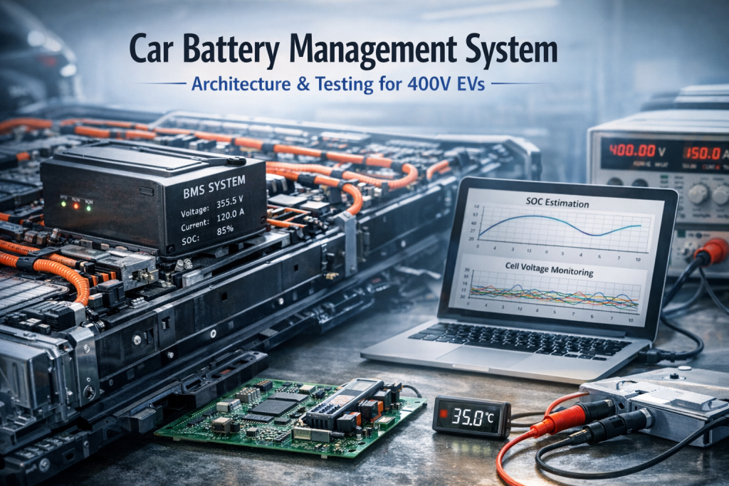
1. Introduction to Modern Car Battery Management Systems
The traction battery acts as the heart of any new energy vehicle, while the car battery management system (BMS) serves as its brain. The way a BMS handles cell monitoring, state estimation, and thermal control directly affects driver safety and vehicle range. By reading real-time parameters like voltage, current, and temperature, the BMS accurately estimates the State of Charge (SOC), State of Health (SOH), and State of Power (SOP). It acts as the main hub connecting the battery pack with the Vehicle Control Unit (VCU) and Motor Control Unit (MCU).
Right now, engineers are pushing toward high-voltage platforms (400V/800V) and integrated domain control. At the same time, we must meet strict automotive-grade standards, such as ISO 26262 ASIL-B/D and GB/T 38664-2020. This guide breaks down a highly reliable car battery management system designed for both passenger and commercial vehicles. We will look at how to solve common engineering problems like bad estimation accuracy, slow thermal responses, and low balancing efficiency.
2. Overall Architecture of the Car Battery Management System
A solid car battery management system follows a simple rule: keep it safe, precise, reliable, and cost-efficient. The setup below uses a Distributed Architecture. This layout mixes strong signal clarity with easy scalability. It easily fits 100-150 series cell packs in passenger cars and 200-300 series cell packs in commercial trucks. It works with both NCM (Ternary Lithium) and LFP (Lithium Iron Phosphate) cells, fits 400V platforms, and handles fast and slow charging.
2.1 Core System Components
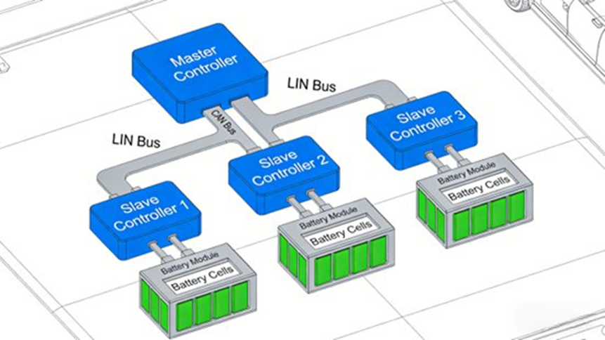
The distributed BMS breaks down into several distinct modules:
- Battery Management Unit (BMU): The main controller. Using a 32-bit automotive-grade MCU (e.g., NXP S32K3xx, Infineon AURIX TC3xx), it processes cell data, runs SOC/SOH/SOP algorithms, controls balancing, and talks to the vehicle. It meets ISO 26262 ASIL-B requirements with built-in fault diagnostics.
- Cell Supervisory Circuit (CSC): Uses dedicated cell monitoring ICs (e.g., ADI LTC6813, TI BQ79616). Each unit monitors 12-16 cells in series. It captures voltage (±1mV precision) and temperature (±1°C precision), carries out balancing commands, and sends data back via a daisy-chain setup.
- Communication Module: Runs a dual-bus design using CAN 2.0B (500kbps) and CAN FD (2Mbps) for vehicle and charger data. A 1Mbps daisy-chain link handles BMU-CSC data transfer, which improves wiring layout and EMI resistance.
- Power Supply Module: Takes a 9V-16V input from the 12V vehicle net and steps it down to a stable 5V and 3.3V. It includes reverse polarity, over-current, and surge protection.
- Auxiliary Detection Module: Measures total voltage, total current (via a shunt resistor and sensor with ±0.5% precision), insulation resistance (balanced bridge method, ±5kΩ precision), and links to vehicle crash sensors.
2.2 Engineering Constraints and Standards
- Environment: Operating temp -40°C to 85°C; Storage -40°C to 125°C. Withstands vehicle vibration (10-2000Hz, 10g), shock (50g, 11ms), and carries an IP67 rating.
- Functional Safety: ISO 26262 ASIL-B compliant, ≥90% fault diagnostic coverage, ≤10ms fault response time, keeping storage for ≥1000 fault records.
- EMC: Meets GB/T 21437.2-2008 and ISO 11452 series. Radiated emissions ≤30dBμV/m (30-1000MHz); ESD ±8kV (contact) / ±15kV (air).
3. Hardware Circuit Design
Solid hardware keeps the BMS running safely.
3.1 Cell Monitoring Circuit
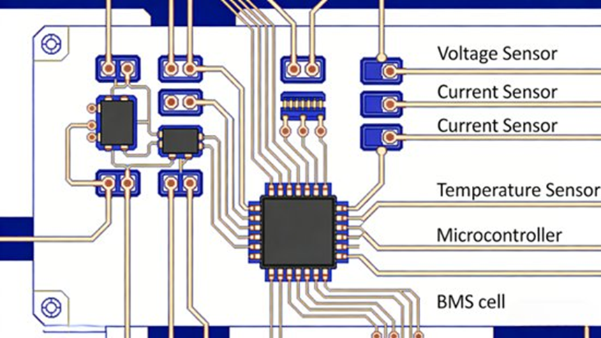
Using the ADI LTC6813 chip (12-series support, built-in 16-bit ADC, 0-5V range), this circuit handles differential voltage sampling. We use a 0.1μF decoupling capacitor and TVS diodes to prevent over-voltage damage. For temperature, we mount 10kΩ NTC thermistors (B-value 3950) on cell surfaces (4-6 points per CSC), combined with a 1kΩ filter resistor. The circuit uses passive balancing (resistor discharging) via built-in switches at a maximum of 200mA. The 2W 100Ω power resistors keep cell voltage deviation ≤5mV.
3.2 Main Control Circuit
The NXP S32K344 automotive MCU (ARM Cortex-M7, 160MHz, 1MB Flash, 256KB RAM) powers the main board. It includes a hardware security module (HSM). The system relies on an LDO regulator (TI TPS7A4700) for 5V to 3.3V conversion. It features an adjustable 10ms-100ms reset circuit and a 16MHz external oscillator. Key signals use redundant dual-channel sampling. An internal watchdog (WDG) prevents lockups, and an I2C-connected EEPROM saves data for at least 10 years without power.
3.3 Communication and Safety Protection Circuits
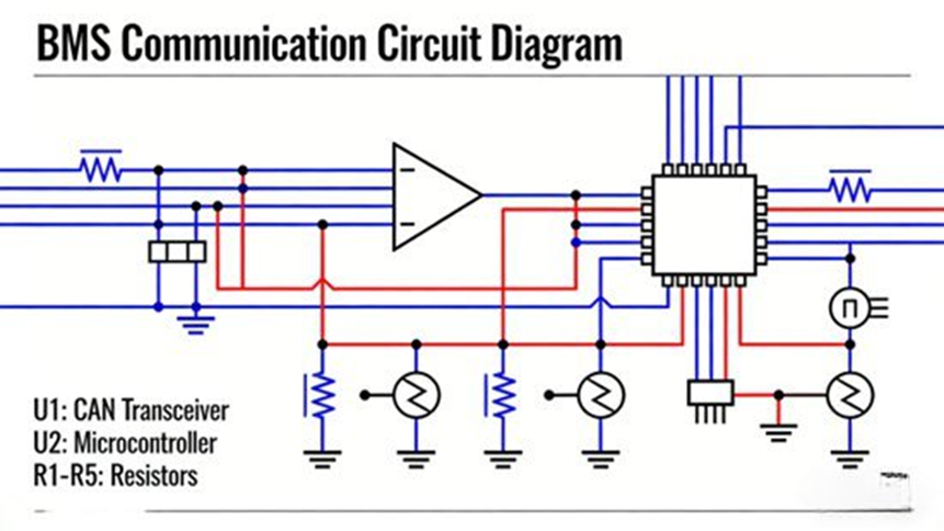
- Communication: We use isolated CAN transceivers (TI ISO1050) with 120Ω terminating resistors. The daisy chain runs differential signals via DAISY_IN/DAISY_OUT pins. If one CSC fails, the system bypasses it immediately.
- Hardware Safety Interventions:
- Over/Under Voltage: Cuts circuits if total voltage passes 420V or drops below 280V (for a 400V platform).
- Over-current: Disconnects relays if discharge passes 300A or fast charge goes above 150A.
- Insulation: Triggers an alarm if resistance drops below 100kΩ/V.
- Thermal: Intervenes if cell temp goes >60°C (discharge), >45°C (charge), or BMS temp goes >85°C.
4. Software Algorithms Powering the System
Running on an RTOS (like FreeRTOS), the software guarantees real-time responses.
4.1 Data Acquisition and Preprocessing
Sampling rates change based on the driving situation: 10Hz (voltage/temp) and 100Hz (current) normally. This speeds up to 50Hz/200Hz during fast charging or hard acceleration. The software uses moving average filters (window size 5-10) and first-order low-pass filters (1Hz cutoff for temperature). The 3σ rule removes extreme outliers (e.g., >4.5V, <2.5V, >85°C, or <-40°C).
4.2 High-Precision SOC Estimation
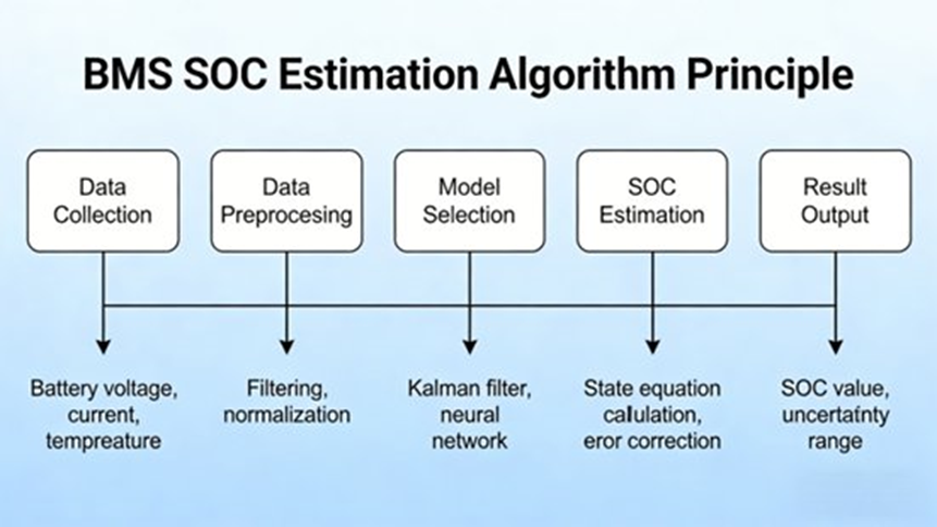
We use a fusion algorithm combining Ah Integration + Extended Kalman Filter (EKF) + Open Circuit Voltage (OCV) Correction:
- Ah Integration: Simple but causes cumulative errors over time.
- EKF: Built on a second-order RC equivalent model to remove measurement noise and track internal resistance dynamically.
- OCV Correction: Runs when the battery rests (current <0.5C for ≥30min) via an OCV-SOC curve lookup to wipe out Ah integration drift.
This combined approach delivers an SOC estimation accuracy of ±2% across the 0-100% range, reacting quickly to sudden current changes.
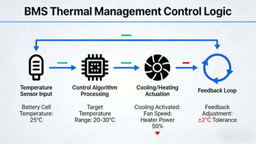
4.3 Balancing and Thermal Management
- Dual-Loop Balancing: Starts when max voltage deviation is >5mV or capacity deviation is >2%. It passively discharges the highest-voltage cells at 200mA. The system checks and adjusts every 10 minutes, stopping when deviation hits ≤3mV. Resistor temperature is capped at 55°C. After 1000 cycles, capacity retention stays ≥80%.
- Fuzzy PID Thermal Control: Batteries operate best between 20°C and 45°C. A Fuzzy PID controller adjusts fan speeds and liquid cooling flow based on current temperatures and rate of change. Target temps are 30°C for normal driving and 35°C for fast charging. PTC heaters turn on to reach >10°C if the outside air drops below freezing.
4.4 Safety Protection and Fault Diagnosis
Using Fault Tree Analysis (FTA), the system applies three intervention levels:
- Level 1 (Minor): Alarm and logging (e.g., slight voltage deviation).
- Level 2 (Moderate): Current limitation and 10s cut-off timer (e.g., minor insulation drop).
- Level 3 (Severe): Immediate circuit cut-off (e.g., over-voltage, thermal runaway).
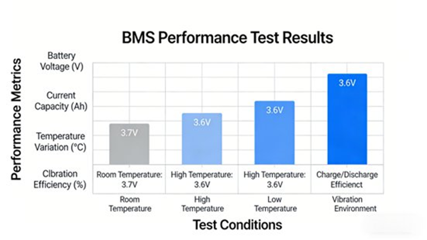
5. Performance Testing and Engineering Validation
We built a multi-condition test platform using a Chroma 62050H-1000V/500A tester and an environmental chamber. We tested a 70Ah/350V/100-series NCM battery pack at a 100Hz/0.01% DAQ rate, following GB/T 38664-2020 and ISO 15118 rules.
5.1 Key Performance Results
- SOC Accuracy (1C/70A discharge at 25°C): Deviation stayed at ≤±1% (100%-80% SOC), ≤±2% (80%-20% SOC), and ≤±1.5% (20%-0% SOC).
- Balancing Efficiency: The system pulled a 15mV artificial deviation down to ≤2.8mV in 45 minutes, shrinking capacity deviation to ≤0.8%.
- Thermal Response (1.5C/105A fast charge at 35°C): Average temp locked in at 35°C ±0.5°C (34.5°C-35.5°C). Max cell temperature never broke 42°C. Spikes (>36°C) cooled within 3 minutes.
- Safety Response: Over-voltage (4.6V) caused an 8ms alarm and a 10ms cut-off. Over-current (350A) dropped to 300A in 5ms. An insulation drop (50kΩ/V) resulted in an immediate cut-off.
5.2 Real-World Engineering Case Study
We installed the BMS into a 400V pure EV (500km range) for a 10,000km road test. The system reached an MTBF of ≥2000 hours. SOC accuracy stayed within ±2% (range error ≤3%), and the battery kept ≥90% capacity after 500 cycles.
Final Thoughts and Future Outlook
This distributed 400V car battery management system combines highly precise hardware with smart fusion algorithms to deliver strong, ASIL-B compliant safety. Looking ahead, battery management will move toward Domain Controller Integration (merging BMS, VCU, and MCU), AI and Machine Learning for better SOH predictions, 800V+ platforms for 3C+ ultra-fast charging, and Cloud-Synergy for remote OTA updates.
Frequently Asked Questions (FAQ) about Car Battery Management Systems
Q1: Why is a Battery Management System critical in electric vehicles (EVs)?
Short Answer: It keeps the battery pack safe, balances cells, and prevents thermal runaway.
A BMS monitors, controls, and protects the battery pack to maximize battery life. EV batteries use hundreds of cells connected together, which must stay within strict voltage and temperature limits. The BMS prevents catastrophic failures by providing protection against overcharge, real-time monitoring, cell balancing, and data communication with vehicle control systems. (Sources: Wikipedia, MDPI)
Q2: What is State of Charge (SOC) and why is it difficult to estimate accurately?
Short Answer: It is the battery’s fuel gauge, showing remaining capacity.
Accurate estimation is hard because SOC cannot be measured directly. Engineers must calculate it from voltage, current, and temperature. Battery aging, rapid temperature shifts, and sensor noise complicate the math. Modern automotive BMS use fusion algorithms—like combining Ah integration with Extended Kalman Filters (EKF)—to lock in ±2% accuracy. (Source: ScienceDirect)
Q3: What is State of Health (SOH) and how does it affect EV battery performance?
Short Answer: It measures the battery’s current wear and tear compared to a brand-new pack.
An SOH of 100% means new performance, while 70–80% means the battery is nearing the end of its useful automotive life. Battery degradation directly lowers driving range, slows charging, and raises internal resistance. A BMS constantly evaluates SOH by tracking capacity fade and thermal stress history. (Sources: Wikipedia, MDPI)
Q4: Why is cell balancing necessary in EV battery packs?
Short Answer: It fixes voltage differences between cells, preventing early wear and maximizing pack capacity.
Individual cells naturally develop differences in voltage and capacity due to minor manufacturing variances and aging. If left alone, weaker cells hit their charge limits too early, reducing the total usable capacity of the car.
- Passive Balancing: Burns off excess energy as heat (simple and cost-efficient).
- Active Balancing: Moves energy from strong cells to weak cells (higher efficiency, but requires complex circuits). (Sources: Wikipedia, ScienceDirect)
Q5: What are the common architectures used in automotive BMS design?
Short Answer: Engineers use centralized, modular, distributed, or wireless setups based on the battery pack size.
- Centralized BMS: One controller connects to all cells (lower cost).
- Modular BMS: Each module has its own controller (highly scalable).
- Distributed BMS: Electronics sit right next to each cell (improves accuracy and fault tolerance; very common in modern EVs).
- Wireless BMS: A newer setup that cuts out heavy communication wiring harnesses to save space and weight. (Source: evengineeringonline.com)
