

< Back to Sample & Prototype Production
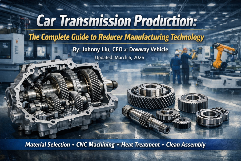
By: Johnny Liu, CEO at Dowway Vehicle
Updated: March 6, 2026
As the CEO of Dowway Vehicle, I have overseen mass production for countless automotive transmission components. I drew on decades of engineering practice and production line management to write this guide. It breaks down the entire manufacturing ecosystem of automotive power transmission reducers. We will cover everything from material selection and precision machining to clean assembly and quality verification. Whether you build traditional internal combustion engines or modern new energy vehicles (NEVs), mastering these production techniques is vital for high performance and reliability.
- 1. Introduction to Car Transmission Production
- 2. Core Structure and Design Benchmarks in Reducer Production
- 3. Material Selection and Blank Preparation in Manufacturing
- 4. Precision CNC Machining: The Core of Car Transmission Production
- 5. Heat Treatment and Surface Strengthening Technologies
- 6. Precision Grinding and Final Finishing
- 7. Clean Assembly and Torque Control Standards
- 8. Full-Process Quality Inspection and Performance Verification
- 9. Common Technical Difficulties and Solutions
- 10. Final Thoughts and Future Trends
- 11. Frequently Asked Questions (FAQ)
1. Introduction to Car Transmission Production
The automotive power transmission reducer is the core hub connecting the power source (engine or electric motor) to the wheels. Its primary function is to convert the high-speed, low-torque output of the power source into the low-speed, high-torque drive required by the wheels. It must do this while ensuring transmission efficiency, stability, and durability. These factors directly dictate the vehicle’s dynamic response, fuel economy (or power consumption), and ride smoothness.
As new energy vehicles (NEVs) move towards higher power density, higher speeds, and lower noise, transmission production faces stricter requirements. Today, gear precision needs to reach ISO 4-5 grades, transmission efficiency must hit ≥97%, and the service life should exceed 300,000 kilometers. Based on real mass-production line practices, this guide details the technical essentials, equipment selection, and quality control methods across all production stages.
2. Core Structure and Design Benchmarks in Reducer Production
2.1 Core Components of a Transmission Reducer
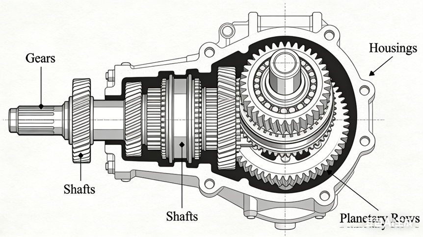
Mainstream automotive reducer structures fall into two categories: built-in reducers for traditional fuel vehicle transmissions (mostly two-stage parallel shaft helical gears) and integrated reducers for NEV electric drive axles (mostly planetary gear set + main reducer + differential). Core components include:
- Gears: Driving gears, driven gears, planetary gears, sun gears.
- Shafts: Input shafts, output shafts, planet carriers.
- Housings: Reducer housings, differential housings.
- Accessories: Bearings, seals, and fasteners.
2.2 Critical Design and Production Benchmarks
Production design must follow the principles of “unified benchmarks, precise adaptation, and process feasibility”:
- Geometric Benchmarks: We use the center hole of shaft parts and the inner hole/end face of gears as a unified benchmark. This ensures coaxiality ≤0.01mm and end face runout ≤0.008mm.
- Precision Benchmarks: Gear precision sits strictly at ISO 4-5. Cumulative pitch deviation (Fp) remains ≤0.015mm, and profile error (Fa) stays ≤0.005mm. Housing hole center distance tolerance is ±0.01mm, while flatness is 0.02mm/100mm.
- Performance Benchmarks: Transmission efficiency must reach ≥97% (NEV reducers ≥98%). Operating noise should not exceed 65dB (no-load). The peak torque capacity ranges from 2000-5000 N·m. The unit must run with no leakage or abnormal wear under extreme temperatures (-40°C to 120°C).
3. Material Selection and Blank Preparation in Manufacturing
Material properties directly determine the load-bearing capacity, wear resistance, and lifespan of the reducer.
3.1 Core Material Selection for Transmission Parts
| Component Type | Selected Material | Material Standards | Core Performance Requirements |
| Gears (Driving, Driven, etc.) | Low-carbon alloy carburizing steel | 20CrMnTiH, 20CrMoH, 20MnCr5 | Excellent core toughness (impact toughness ≥40J/cm²), high surface hardness (58-62HRC), pitting and bending fatigue resistance. |
| Shafts (Input, Output, etc.) | Alloy structural steel | 40Cr, 42CrMo | High strength (tensile strength ≥980MPa), good hardenability and wear resistance, high coaxiality precision. |
| Reducer Housings | Cast aluminum / Nodular cast iron | AlSi9Cu3 (Aluminum), QT450-10 (Iron) | Lightweight (aluminum) / high strength (iron), excellent casting performance and sealing, high hole precision. |
| Planet Carriers | High-strength cast steel / Forged steel | 20CrMnTi, 40Cr | Impact and deformation resistance, planetary hole coaxiality ≤0.01mm. |
3.2 Mass Production Blank Preparation Techniques
The goal here is to eliminate internal defects and ensure dimensional consistency. This reduces allowances for subsequent precision machining:
- Precision Cutting: This process uses CNC saws or laser cutting machines to guarantee end face perpendicularity of ≤0.05mm and a cutting tolerance of ±0.1mm.
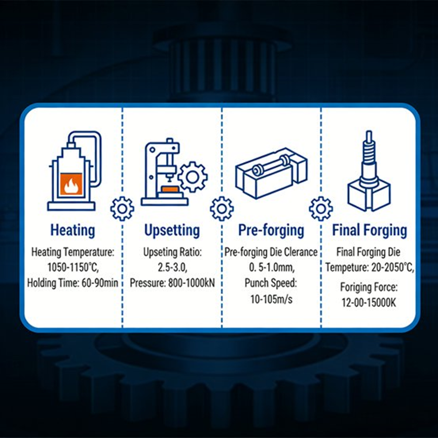
- Hot Precision Forging / Closed-Die Forging: Workers heat gear and shaft blanks to 1000-1150°C. They form them via upsetting, followed by pre-forging and final forging to achieve near-net gear shapes (allowance ≤0.3mm).
- Isothermal Normalizing: Teams heat blanks to 860-880°C, hold them for 2-3 hours, and then furnace cool them. This step removes forging stress and controls hardness to 160-180HB for much better machinability.
- Shot Peening: Using 0.2-0.5mm pellets removes oxide scale, bringing surface roughness Ra down to ≤3.2μm.
- Blank Inspection: Inspectors check the pieces using a metallographic microscope for structure, a hardness tester, and calipers. Defective blanks go straight to the rejection bin.
4. Precision CNC Machining: The Core of Car Transmission Production
The heart of reducer machining is “precision control.” You need specialized equipment and highly strict process management to make it work.
4.1 Datum Machining (Rough and Finish Turning)
- Equipment: CNC lathes/mill-turn centers (e.g., DMG MORI CTX 310) with positioning precision ≤0.005mm.
- Process: Rough turning handles outer circles and end faces, while finish turning shapes the center holes. This guarantees coaxiality ≤0.01mm and end face runout ≤0.008mm. We maintain gear blank inner hole tolerance at ±0.002mm.
- Parameters: Cutting speed hits 80-120m/min, feed rate is 0.1-0.2mm/r, and depth of cut sits at 0.5-1.0mm. Operators use carbide tools with TiN coating.
4.2 Gear Profile Forming Processes
- Soft Gear Machining (Medium/Low Load): The process begins with hobbing, followed immediately by shaving. Hobbing speed hits 30-50m/min (Ra ≤1.6μm). Shaving clears out residual errors, hitting Ra ≤0.8μm and ISO 5 precision.
- Hard Gear Machining (High Load/Speed NEVs): Teams hob the gear, apply heat treatment, and then move to grinding. Hobbing leaves a grinding allowance of 0.05-0.15mm. Grinding relies on a CNC worm wheel gear grinding machine (e.g., KAPP KX300) with CBN ceramic wheels (25-35m/s) in 5-axis machining. The result is Ra ≤0.4μm and ISO 4 precision with zero grinding burns or cracks.
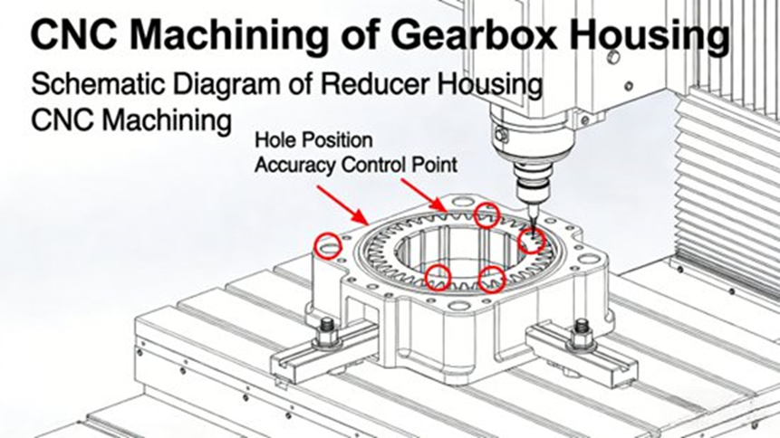
4.3 Precision Machining of Housings and Planet Carriers
- Equipment: 5-axis double-column machining centers (e.g., HAAS UMC-750) handle the housings. Horizontal machining centers take care of the carriers.
- Precision Control: Hole center distance tolerance is ±0.01mm, and flatness is 0.02mm/100mm. Quality teams strictly control coaxiality, parallelism, and perpendicularity according to GD&T (Geometric Dimensioning and Tolerancing).
- Optimization: We rely on “single setup, multi-process machining” to cut down on clamping errors.
5. Heat Treatment and Surface Strengthening Technologies
Once precision CNC machining finishes, components go straight into heat treatment. The end goal is to achieve “high surface hardness, high core toughness” while keeping deformation to an absolute minimum.
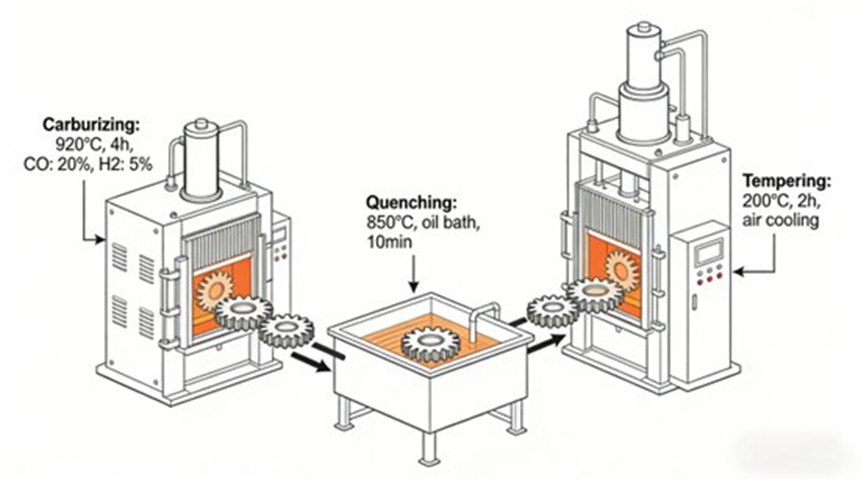
5.1 Core Heat Treatment Processes (Carburizing + Quenching + Tempering)
- Carburizing: We run this in a controlled atmosphere furnace at 920-930°C. Carbon potential stays at 0.9-1.0%. Case depth reaches 0.8-1.2mm for gears and 0.5-0.8mm for shafts.
- Quenching: Components cool down to 850-870°C, then drop into an oil quench (oil temp 60-80°C). Dedicated fixtures prevent distortion. Surface hardness hits 58-62HRC, and core hardness rests at 30-40HRC.
- Low-Temperature Tempering: Processed right away at 180-200°C for 2-3 hours, then furnace cooled to relieve stress.
- Post-Treatment: Shot peening (0.1-0.2mm pellets) boosts residual compressive stress and fatigue resistance. Gear surface Ra drops to ≤0.8μm.
5.2 Controlling Heat Treatment Deformation: A Key Challenge
- Pre-treatment: Isothermal normalizing ensures a highly uniform metallographic structure.
- Fixture Optimization: Dedicated fixtures spread stress evenly during both heating and cooling.
- Allowance Reservation: We leave a grinding allowance of 0.05-0.15mm before heat treatment to correct any post-treatment distortion.
6. Precision Grinding and Final Finishing
Final finishing strips away preceding errors to meet rigorous design limits.
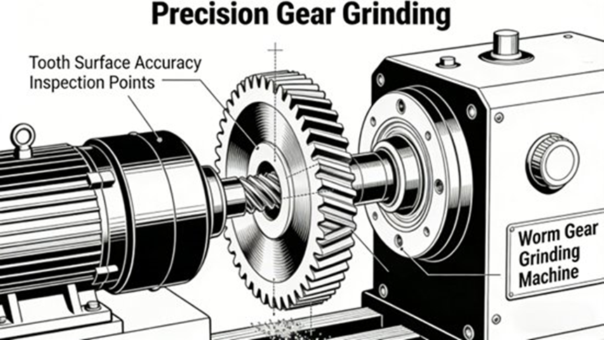
6.1 Advanced Gear Grinding Techniques
- Wheels: We use CBN ceramic bonded wheels (80-120 mesh, 25-35m/s), dynamically balanced for stability.
- Parameters: Feed rate holds at 0.005-0.015mm/pass, and speed is 10-15m/min. The team follows a “rough → semi-finish → finish” three-step method.
- Quality: Ra ≤0.4μm, ISO 4-5 precision, Fp ≤0.015mm, Fa ≤0.005mm. Gear measuring centers monitor the entire process in real time.
6.2 Shaft Diameter and End Face Precision Grinding
- Equipment: Cylindrical grinders (e.g., M1432B) and surface grinders with positioning precision ≤0.002mm.
- Requirements: Shaft diameter tolerance ±0.002mm, roundness ≤0.001mm, Ra ≤0.2μm. End face flatness ≤0.005mm, perpendicularity ≤0.008mm.
7. Clean Assembly and Torque Control Standards
Assembly quality directly affects transmission efficiency, NVH (Noise, Vibration, and Harshness), and overall reliability.
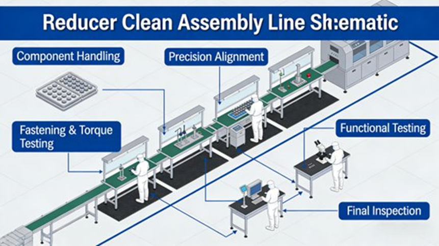
7.1 Assembly Environment Requirements
Assembly takes place in ISO Class 7 (Class 10,000) or ISO Class 8 (Class 100,000) cleanrooms. We keep the temperature at 22±2°C and humidity between 40-60%. Airborne particles remain at ≤10,000/m³ (Class 10,000) so dust and iron filings never cause abnormal noise.
7.2 Core Assembly Steps and Quality Control
- Part Cleaning: Ultrasonic cleaning (50-60°C, 10-15 min) runs first, followed immediately by a high-pressure air purge (0.4-0.6MPa). Cleanliness easily hits NAS 8.
- Bearing Assembly: The team uses induction heating (80-100°C). They strictly control axial clearance at 0.01-0.03mm.
- Gear Meshing: Clearance adjusts to 0.1-0.3mm (depending on module). We check contact patterns to verify uniform distribution and eliminate edge loading.
- Bolt Tightening: Workers apply the Torque + Angle method. For example, they torque M10 bolts to 25-30N·m with an angle deviation of ±5°. The system records all data for traceability.
- Sealing and Oiling: We use liquid gaskets or metal shims. Finally, the unit receives dedicated low-viscosity reducer oil.
7.3 Post-Assembly Initial Inspection
The unit undergoes a no-load test run (500-1000r/min for 10-15 min) to check for abnormal noise, leaks, and temperature spikes (≤20°C).
8. Full-Process Quality Inspection and Performance Verification
8.1 In-Process Quality Control (SPC Management)
- Machining: CMM runs geometry checks for housings and shafts. Gear testing centers verify profile and pitch. We require 100% inspection for critical dimensions and ≥10% sampling for everything else.
- Heat Treatment: Inspectors check Rockwell hardness and run metallographic checks (≥5 pieces per batch).
- SPC Control: Statistical Process Control charts track critical dimensions, securing CPK ≥ 1.33.
8.2 Finished Product Performance Verification (Bench Testing)
- Run-in Test: Units run at 50-70% rated torque, 1000-2000r/min, for 2-4 hours to relieve assembly stress.
- Efficiency Test: Must reach ≥97% (NEVs ≥98%).
- NVH Test: Noise holds at ≤65dB, and vibration acceleration stays at ≤0.5g.
- Sealing Test: Air pressure (0.3-0.5MPa) or oil pressure (1.0-1.5MPa) holds steady for 30 mins.
- Durability Test: Accelerated life testing runs for ≥1000 hours.
- Extreme Temp Test: The unit must start and run in -40°C to 120°C chambers.
9. Common Technical Difficulties and Solutions
| Technical Difficulty | Root Causes | Solutions |
| Excessive Heat Treatment Deformation | Uneven blank structure, improper fixturing, process parameter fluctuations. | Optimize isothermal normalizing, use dedicated fixtures, strictly control temp/cooling rates, reserve sufficient grinding allowance. |
| Poor Gear Tooth Contact | Profile errors, lead deviation, inaccurate center distance. | Optimize grinding, use profile modification/crowning, improve housing hole precision, strictly control meshing clearance. |
| Abnormal Assembly Noise | Insufficient gear precision, improper bearing preload, poor cleanliness. | Improve gear grinding precision, optimize bearing preload, enforce strict cleanliness standards, adjust meshing patterns. |
| Early Failure (Pitting/Fracture) | Low material purity, improper heat treatment, excessive residual stress. | Use high-purity materials, optimize carburizing/quenching, add shot peening, enforce strict process quality control. |
10. Final Thoughts and Future Trends
Building automotive transmission reducers requires a highly systematic engineering approach. It covers materials, precision machining, heat treatment, assembly, and inspection. By strictly following the precision control measures outlined in this guide, manufacturers can reliably hit ISO 4-5 gear precision, ≥97% efficiency, and a lifespan running well beyond 300,000 kilometers.
Looking ahead, NEVs demand higher power density and intelligence. Production will naturally shift toward advanced lightweight materials (like carbon fiber composites and high-strength aluminum), 3D printing, laser machining, and smart manufacturing run by IoT and industrial robotics. This evolution will secure the green, efficient, and ultra-reliable future of car transmission production.
11. Frequently Asked Questions (FAQ)
Below are five of the most frequently discussed questions related to car transmission production, based on industry articles, manufacturing guides, and engineering literature.
1. What are the main stages in car transmission production?
- Short Answer: It involves design, material selection, precision machining, heat treatment, assembly, and rigorous testing.
- Detailed Answer: First, engineers design the transmission using CAD and simulation tools to determine gear geometry and load capacity. Next, components such as gears, shafts, and housings are manufactured through machining processes like CNC turning, milling, and gear cutting. Heat treatment processes (e.g., carburizing) follow to improve strength and wear resistance. Finally, workers assemble the components and subject the final unit to rigorous testing to verify performance, efficiency, and durability.
2. Why is transmission manufacturing considered highly difficult?
- Short Answer: It requires extremely tight tolerances across many interacting, high-speed parts.
- Detailed Answer: Transmission manufacturing is intricate because it demands immense precision. Even minor deviations in gear tooth geometry or shaft alignment will easily degrade noise levels, efficiency, and durability. Modern transmissions contain many parts—including gears, synchronizers, bearings, and control systems. They must all work together perfectly to transfer engine torque under varying loads and speeds. Precision machining and strict quality control guarantee this reliability over a long service life.
3. What materials are commonly used in transmission production?
- Short Answer: Manufacturers rely heavily on high-strength alloy steels, cast iron, and lightweight aluminum.
- Detailed Answer: Most transmission components use high-strength alloy steels. Gears and shafts require these metals to deliver excellent fatigue resistance and durability. Housings are usually manufactured from cast iron or aluminum alloys, depending on the need for weight reduction, rigidity, or thermal performance. Engineers match material selection directly to operating conditions, since transmissions must handle high torque, repeated stress cycles, and friction for years.
4. How do manufacturers ensure the quality and reliability of transmissions?
- Short Answer: Teams use multi-stage inspections, from dimension checks to real-world bench testing.
- Detailed Answer: Manufacturers secure quality through multi-stage inspections and functional testing throughout the production process. Quality teams run dimensional measurements, hardness tests, and surface roughness checks right after machining and heat treatment. During final assembly, they verify gear alignment, preload, and backlash. Finally, completed transmissions undergo operational tests that simulate real driving conditions to confirm torque transfer efficiency, noise levels, and durability.
5. What are the major challenges in transmission production today?
- Short Answer: The main hurdles are maintaining tight tolerances, keeping costs low, and adapting to electric vehicles.
Detailed Answer: Key hurdles include maintaining ultra-high precision, cutting down manufacturing costs, and adopting new technologies. Transmission components must hit strict tolerances, as tiny errors lead straight to scrap parts or performance drops. Manufacturers now lean on automation, robotics, and smart systems to keep output consistent and productive. Additionally, the industry faces massive pressure to build lighter, more efficient transmissions that fit hybrid and electric vehicles while keeping costs realistic.
