

< Back to Sample & Prototype Production
By Johnny Liu, CEO at Dowway Vehicle
Published: March 6, 2026 | Read Time: 15 mins
- Key Takeaways
- 1. Parts Pre-Treatment
- 2. Sub-Assembly Manufacturing
- 3. Main Body Framing (Marriage)
- 4. Final Assembly and Testing
- Precision Positioning Technologies
- Efficient Joining Techniques
- Automated Assembly Solutions
- 1. What is Body-in-White (BIW) in automotive manufacturing?
- 2. Why is the Body-in-White stage important?
- 3. What processes are involved in BIW assembly?
- 4. What materials are commonly used in Body-in-White structures?
- 5. What are the common challenges in BIW assembly?
- BIW Assembly: Quick Summary
Key Takeaways
- What is it? Body in White (BIW) assembly is the stage where 300-500 sheet metal parts join to form the vehicle’s bare structural shell. It makes up 30%-40% of the total vehicle weight.
- Strict Tolerances: Engineers must keep critical dimensional tolerances at ≤±0.3mm.
- Core Workflow: The line moves through parts pre-treatment, sub-assembly, main body framing (marriage), and final testing.
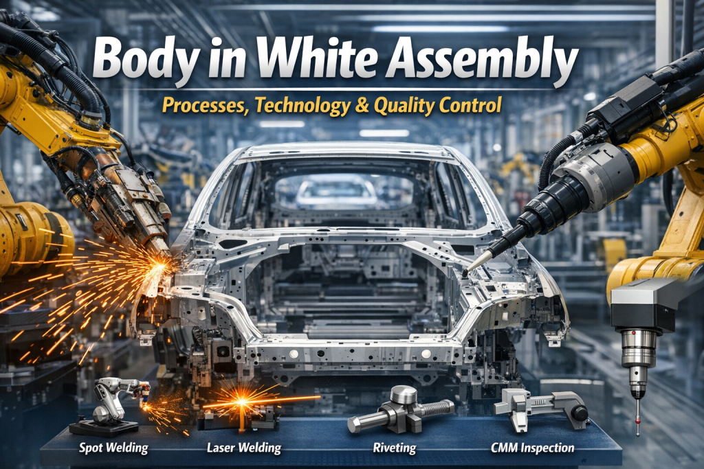
- Key Technologies: The process relies heavily on automated flexible fixtures, resistance spot welding, laser welding, Self-Piercing Riveting (SPR), and structural adhesives.
- Quality Control: Factories use a Three-Tier System (blue light scanning, OTS, and CMM) to hit a dimensional CPK value of ≥1.33.
Introduction to Body in White Assembly
Think of the Body in White (BIW) as the skeleton of a car. It is the core load-bearing structure and the direct installation foundation for the powertrain, chassis, electrical systems, and interior trims. A completed BIW consists of structural components (longitudinal beams, cross members, pillars) and closures (doors, hoods, fenders). Workers and robots connect these through welding, riveting, and adhesive bonding long before any painting or engine installation happens.
Making up 30% to 40% of the total vehicle weight, BIW assembly is arguably the most technically demanding phase in auto manufacturing. Unlike standard mechanical assembly, it involves a massive part count—typically 300 to 500 parts for a single passenger car. It also requires extreme precision, with critical dimensional tolerances strictly held at ≤±0.3mm.
Pushed by rapid progress in vehicle lightweighting, smart factories, and electrification, builders are heavily adopting high-strength steel, aluminum alloys, and carbon fiber. Because of this, BIW assembly is quickly moving toward higher automation and extreme precision.
The Step-by-Step Assembly Process
The assembly follows a strict cascading workflow. A single deviation in these interconnected steps can ruin the final vehicle’s safety and NVH (Noise, Vibration, and Harshness) performance.
1. Parts Pre-Treatment
Pre-treatment strips away stamping oils, oxidation, and burrs. This guarantees clean surfaces for joining.
- Degreasing: Parts take an alkaline spray and ultrasonic bath at 50–60°C for 2–3 minutes to remove impurities, completely complying with the GB/T 13312-2009 standard.
- Phosphating: A zinc-based phosphating process lays down a uniform film (5–8μm thick). This improves welding conductivity and adhesive grip.
- Deburring: Robots or manual operators grind away edge and hole burrs (keeping burr height ≤0.1mm) to stop positioning errors before they start.
- Dimensional Pre-inspection: Blue light scanners perform 100% online inspection of critical stampings. The system immediately intercepts parts with deviations larger than ±0.2mm.
2. Sub-Assembly Manufacturing
Factories merge individual stampings into functional units first. This decentralization drastically speeds up production.
- Underbody Sub-assembly: Using the “3-2-1” locating principle, resistance spot welding connects the cross members, center tunnel, and floor panels. Weld pitch stays tightly controlled at 50–80mm, with a nugget diameter ≥6mm (or ≥5mm for high-strength steel) to guarantee floor rigidity.
- Side Body Sub-assembly: This forms the core side-impact structure. The line uses a mix of laser and spot welding. Laser weld width stays at 0.8–1.2mm with a straightness of ≤0.5mm/m to keep the outer panel perfectly flat.
- Front Compartment Sub-assembly: This area is critical for engine drops. Parallelism of the front longitudinal beam must sit at ≤0.2mm/m, alongside a front dash panel flatness of ≤0.3mm/1000mm. Stud welding requires a pull-off force of ≥3000N.
- Closures (Door & Hood) Sub-assembly: Inner and outer panels join via hemming under a pressure of 8–12kN. After operators install hinges, they adjust the gap to 0.5–1.0mm and the flush to ≤±0.5mm for perfect weather sealing.
3. Main Body Framing (Marriage)
Robots marry the core sub-assemblies in the main framing station.
- Framing Sequence: The process follows a “bottom-up, inside-out” rule. The underbody clamps down first. Next come the side panels (docking gap ≤0.3mm), the roof (sealed with continuous laser welding), and finally the rear panel.
- Precision Control: By using flexible framing fixtures and robotic handlers, positioning accuracy hits ±0.05mm. An Online Tracking System (OTS) watches the process in real-time, holding the overall body dimensional deviation under ±0.5mm.
4. Final Assembly and Testing
- Closure Installation & Sealing: Automated nozzles apply structural sealant to joints and chassis connection points. They keep the adhesive layer 2–3mm thick and 5–8mm wide to boost overall stiffness.
- Comprehensive Testing:
- Dimensional: Coordinate Measuring Machines (CMM) run full-scale checks at an accuracy of ±0.05mm. They demand a CPK value ≥1.33 for critical dimensions.
- Welding Quality: Ultrasonic Testing (UT) hunts for internal flaws. Pores must measure ≤0.3mm in diameter, with a strict limit of ≤2 pores per 50mm of weld seam.
- Visual: Dents on outer panels cannot exceed 0.2mm in depth and 3mm in diameter.
Core Technologies Driving Production
Precision Positioning Technologies
- RPS (Reference Point System): This translates 3D CAD models into physical hard points. Critical reference plane flatness must hit ≤0.3mm/1000mm, and reference hole position tolerance cannot exceed ±0.2mm.
- Flexible Fixtures: Modular fixtures easily adapt to multi-model lines. The clearance between locating pins and part holes is a tiny ≤0.1mm. Hydraulic clamps push 6–8 bar of pressure to secure critical joints securely.
- Machine Vision: Smart cameras spot feature points and correct robotic paths in real-time, driving positioning accuracy down to ±0.03mm.
Efficient Joining Techniques
- Resistance Spot Welding (RSW): This handles over 80% of all BIW welding. Process parameters are strict: electrode tip diameter φ6–8mm, current 8–12kA, time 0.2–0.5s, and force 3–5kN. Indentation depth must remain ≤20%–30% of sheet thickness. Tensile strength needs to reach ≥8kN (≥3kN for aluminum). Spatter diameter must be ≤0.5mm (max 3 per spot).
- Laser Welding: Utilizing 3–4kW fiber lasers at speeds of 6–8m/min (weld width 0.8-1.2mm). This method drops the total weld spot count by 30% while bumping body rigidity by 15%–20%.
- Self-Piercing Riveting (SPR): SPR joins dissimilar metals without pre-drilled holes. Rivet pitch sits at 80–100mm, requiring a pull-off force of ≥5kN.
- Structural Adhesives: Robots apply glue at speeds of 100–150mm/s (trajectory deviation ≤±0.5mm). The material shear strength must reach ≥15MPa.
Automated Assembly Solutions
A modern BIW line runs 200 to 300 6-axis welding robots (repeat positioning accuracy ±0.05mm). They can push out 60 units/hour—roughly a 3–4x efficiency jump over manual lines. Electric Monorail Systems (EMS) and Automated Guided Vehicles (AGV) move parts with a transport accuracy of ±0.1mm. MES software handles digital traceability to build “one file per car.”
Strict Quality Control
- Parts Quality: Teams test materials for exact composition (like carbon equivalent for steel or alloy ratios for aluminum). Stamping dimensional deviations must stay ≤±0.2mm.
- Process Parameters: Technicians inspect welding parameters every 2 hours. They calibrate fixture clamping force and accuracy daily.
- Dimensional Accuracy: The line relies on a Three-Tier System: Blue light scanning for sub-assemblies → OTS for framing → Final CMM inspection (CPK ≥1.33, overall deviation ≤±0.5mm).
- Weld Integrity: UT and X-ray checks are non-negotiable. Internal cracks must be ≤0.5mm. Any substandard weld gets ground down and re-welded.
What’s Next for BIW Assembly
- Lightweight Material Assembly: Engineers are refining SPR and Flow Drill Screws (FDS) parameters to fix strength and deformation problems when joining dissimilar metals (like steel-to-aluminum or aluminum-to-carbon fiber).
- Digitalization & AI: Builders are using digital twins to run virtual assembly simulations. This predicts dimensional errors and refines the process before physical parts ever touch.
- Flexible Production: Factories are upgrading automated conveyors and framing fixtures to switch car models rapidly (≤30 minutes) using modular assembly cells.
- Green Manufacturing: The industry is switching to eco-friendly structural adhesives and chrome-free passivators while tweaking welding setups to drop energy use and fumes.
Top 5 Frequently Asked Questions about BIW Assembly
1. What is Body-in-White (BIW) in automotive manufacturing?
Short Answer: BIW is the welded sheet-metal body shell of a car before painting and before adding the engine or interior.
Details: At this stage, the vehicle is essentially a bare structural frame. It includes the floor pan, side panels, roof structure, A/B/C pillars, and rear body structure. Factory robots join these components using spot welding, laser welding, riveting, clinching, and bonding. The BIW structure acts as the foundation of the entire vehicle, locking in its geometry and mounting points.
2. Why is the Body-in-White stage important?
Short Answer: It forms the structural foundation of the car, directly determining crash safety, stiffness, and overall dimensional accuracy.
Details: * Crash Safety: The bare shell absorbs and distributes collision energy.
- Torsional Rigidity: A stiff body improves handling, high-speed stability, and ride comfort.
- Dimensional Accuracy: Exact dimensions guarantee that downstream parts (like glass and doors) fit perfectly.
- NVH: The frame design controls the acoustic noise inside the cabin.
3. What processes are involved in BIW assembly?
Short Answer: The workflow moves from stamping and positioning to joining, hemming, and final digital inspection.
Details: 1. Sheet Metal Stamping: Presses form flat sheets into distinct panels.
2. Panel Positioning: Jigs and fixtures lock parts into exact coordinates.
3. Joining Processes: Robots apply resistance spot welding, laser welding, and structural glue.
4. Hemming Operations: Machines fold the edges of outer panels to build doors and hoods.
5. Inspection: Scanners and CMM probes verify all tolerances.
4. What materials are commonly used in Body-in-White structures?
Short Answer: Manufacturers rely on a mix of high-strength steel, aluminum, and sometimes carbon fiber to balance weight and safety.
Details: * High-Strength Steel (HSS): The go-to choice for general structural strength.
- Ultra-High-Strength Steel (UHSS): Placed specifically in crash-critical zones.
- Aluminum Alloys: Crucial for shedding vehicle weight to boost fuel economy or EV range.
- Advanced Composites: Reserved mostly for premium sports cars to maximize the stiffness-to-weight ratio.
5. What are the common challenges in BIW assembly?
Short Answer: The main hurdles include maintaining exact fixture alignment, preventing weld defects, and managing thermal distortion.
Details: * Fixture Misalignment: Even a tiny slip in positioning alters the whole body geometry.
- Welding Defects: Weak welds, internal porosity, or heavy spatter ruin joint strength.
- Dimensional Variation: Minor part tolerances can stack up across hundreds of pieces.
- Material Distortion: Heavy heat from welding often causes thin sheet metals to warp.
BIW Assembly: Quick Summary
| Question | Key Insight |
| What is BIW? | The welded vehicle body shell before painting and final assembly. |
| Why is it important? | It determines crash safety, torsional stiffness, and dimensional accuracy. |
| What processes are used? | Stamping, fixturing, welding, hemming, and digital inspection. |
| What materials are used? | High-strength steel, aluminum alloys, and advanced composites. |
| What challenges occur? | Managing weld quality, fixture alignment, and dimensional variations. |
