


< Back to Automotive Simulation Toolchain
Author: Johnny Liu, CEO at Dowway Vehicle
Published: March 12, 2026
Last Updated: March 12, 2026
Vehicle development has changed a lot in the last few years. EV programs move fast. Smart vehicle functions add more system links. Weight, safety, NVH, battery performance, cost, and timing all matter at once. Because of that, automotive structural analysis software is no longer just a check at the end of design. It now sits much closer to the center of product development.
This article looks at MxSim Mechanical (Chinese Version) as a core structural simulation tool in the automotive R&D toolchain. It covers the software’s architecture, solver and modeling strengths, automotive-specific functions, and three major engineering use cases from the source report: body-in-white stiffness and modal development, battery pack thermal-structural coupling, and chassis subframe topology optimization.
I have kept the original engineering details from the report and reshaped them into a cleaner cluster-page article format. That makes the page easier to publish, easier to scan, and easier for search engines and AI systems to understand.
Author Note
I’m Johnny Liu, CEO at Dowway Vehicle. My work stays close to vehicle engineering, product development, and the tools teams use every day to move a program forward. In real projects, software is not judged only by feature lists. Engineers care about solver stability, model size, workflow fit, hardware support, data exchange, and whether the tool helps them make sound decisions faster. That practical view shapes this article.
- Author Note
- Why Automotive Structural Analysis Software Matters in Modern Vehicle R&D
- What Is MxSim Mechanical in the Automotive CAE Toolchain?
- Core Architecture of MxSim Mechanical
- Technical Advantages of This Automotive Structural Analysis Software
- Application Scenario 1: BIW Stiffness and Modal Development
- Application Scenario 2: Battery Pack Thermal-Structural Coupling
- Application Scenario 3: Chassis Subframe Topology Optimization
- How MxSim Mechanical Fits into the Automotive Development Toolchain
- How It Compares with International CAE Tools
- Top 5 Frequently Asked Questions About MxSim Mechanical
- 1. How does MxSim Mechanical compare with mainstream international CAE tools such as Nastran, Abaqus, or ANSYS?
- 2. What is the low-order high-accuracy element algorithm, and why is it important?
- 3. What types of engineering analyses can MxSim Mechanical perform?
- 4. Can MxSim Mechanical integrate with existing automotive engineering toolchains?
- 5. What hardware environments and computing architectures does MxSim Mechanical support?
Why Automotive Structural Analysis Software Matters in Modern Vehicle R&D
Structural simulation now plays a bigger role in early vehicle development. In older workflows, teams often finished much of the design first and then used CAE to see what failed. If stiffness was too low or stress was too high, they went back and changed the design. That cycle took time.
Now, simulation is used earlier to guide design decisions. That is especially true in EV programs, where the body, chassis, and battery system affect one another more directly.
Body structure affects:
- handling
- safety
- stiffness
- modal behavior
- NVH
Battery pack structure affects:
- thermal safety
- enclosure strength
- deformation
- mounting safety
- long-term reliability
Subframe structure affects:
- weight
- stiffness
- load transfer
- suspension support
- manufacturability
This is why a structural solver needs more than one narrow function. It needs to support stiffness work, modal work, coupled-field problems, dynamic response, and optimization in one engineering flow.
The source report also points to several problems many domestic teams face with international CAE tools:
- limited software controllability
- high software and maintenance cost
- weaker fit for local workflows
- lack of full Chinese operation and support
- reduced flexibility for localized secondary development
MxSim Mechanical is presented as a domestic solution built to answer those needs.
What Is MxSim Mechanical in the Automotive CAE Toolchain?
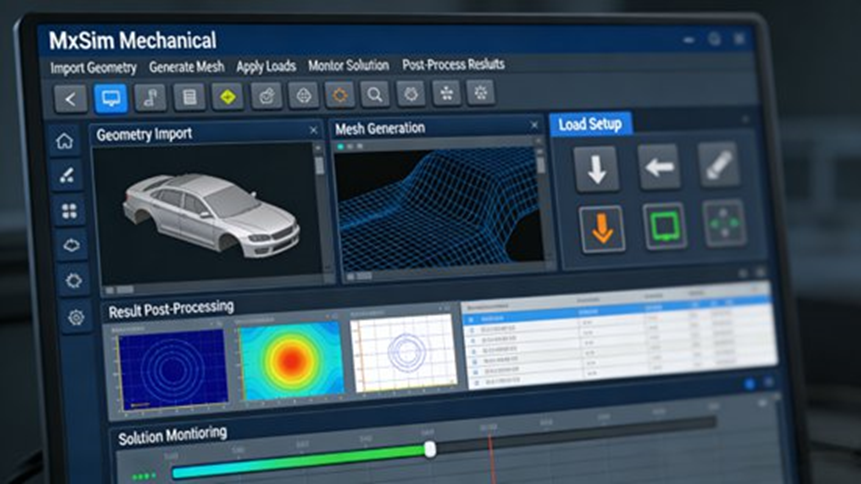
MxSim Mechanical is described as a domestically developed general-purpose structural simulation platform for large engineering models. In automotive work, it acts as a core structural solver and analysis environment inside a wider digital toolchain.
In simple terms, it supports this flow:
CAD modeling → model cleanup → meshing → solving → result review → design improvement
That gives it value beyond a single analysis run. It can sit inside a larger automotive engineering process rather than work as a standalone desktop tool.
The report presents MxSim Mechanical as a product built on more than 30 years of technical work from the State Key Laboratory of Advanced Design and Manufacturing for Vehicle Body at Hunan University. It is described as fully self-controlled at the core algorithm level, which matters to organizations that care about software independence and long-term engineering control.
The Chinese version also matters in daily use. The report notes:
- full Chinese user interface
- Chinese error prompts
- Chinese help documents
- localized function naming
- batch simulation features
- Chinese report generation support
These points may sound simple, but they affect adoption. If engineers can use the tool with less friction, more teams can work with it, not just a small specialist group.
Core Architecture of MxSim Mechanical
The report breaks the platform into four main layers:
- pre- and post-processing
- the core implicit solver
- automotive engineering components
- secondary development interfaces
Pre- and Post-Processing with MxSim GUI
The front-end environment supports full-format geometry import and common CAE preparation tasks. These include:
- automatic geometry cleanup
- midsurface extraction
- adaptive meshing
- templates for thin-walled parts
- templates for large and complex assemblies
This is useful in automotive work because many models combine shell-like thin panels, solid parts, welded areas, and large assemblies.
The software can import geometry from mainstream CAD systems such as:
- CATIA
- UG / NX
- Creo
It also supports common FE formats such as:
- BDF
- INP
- FEM
That helps teams exchange data with other CAE workflows when needed.
MxSim/Implicit Solver for Large Structural Problems
The core solver supports both direct and iterative methods for large sparse equation systems. According to the report, it covers:
- linear static analysis
- nonlinear analysis
- eigenvalue analysis
- modal analysis
- buckling analysis
- stable nonlinear iteration for material, geometric, and contact problems
This makes it suitable for large body, chassis, and battery enclosure models.
Automotive-Specific Engineering Components
The report places real weight on automotive-oriented modeling functions. These include:
- spot weld elements
- seam weld elements
- bolt pretension
- rubber bushing elements
- material libraries for steel, aluminum, composites, and rubber
- custom material constitutive support
This matters because real automotive assemblies depend heavily on connection modeling. A model with poor weld or bushing representation may run, but it may not tell engineers enough.
Secondary Development for Automation
The platform also provides Python and C++ interfaces for:
- parametric modeling
- automatic load application
- batch simulation
- automatic report generation
- customized enterprise workflows
The report notes support for Chinese script writing as well, which helps local engineering teams build their own process tools around the solver.
Technical Advantages of This Automotive Structural Analysis Software
Low-Order High-Accuracy Element Technology
One of the most important points in the report is the low-order high-accuracy element technology.
Standard low-order triangle and tetrahedral elements are often fast and easy to mesh, but they can lose accuracy in difficult structural problems. MxSim Mechanical is described as improving that weak point while keeping the efficiency of low-order meshing.
The report states that this approach can provide:
- more than 50% higher accuracy
- about 5 times faster calculation
This is especially useful in:
- body-in-white thin-walled structures
- battery housing models
- large assemblies where mesh count is already high
In those cases, engineers often cannot keep refining the mesh forever. A stronger low-order element formulation can make a real difference.
High-Performance Computing
The report says the software supports:
- CPU parallel computing
- out-of-core computation
- GPU heterogeneous acceleration
- compatibility with domestic processors such as Kunpeng and Loongson
For automotive work, this matters because models can become very large.
The report gives one example: a new-energy vehicle BIW modal analysis model with about 1.5 million elements achieved a 40% shorter solve time under 8-core GPU acceleration compared with mainstream international tools.
It also mentions the self-developed AMLS solver, which can:
- partition substructures automatically
- use efficient data structures
- apply fine-grained task parallelism
- deliver up to 210 times speed improvement in a 4-GPU setup
These are important engineering points because speed affects how many design loops a team can complete in a program.
Multi-Physics Coverage
The report states that the platform supports several major analysis areas.
Structural field
- linear statics
- elastic-plastic nonlinear analysis
- buckling
- modal analysis
Dynamics
- transient response
- frequency response
- random vibration
- response spectrum analysis
Coupled fields
- thermal-structural coupling
- acoustic-structural coupling
- rigid-flexible multibody dynamics
These functions let engineers work on problems such as:
- BIW stiffness development
- mode placement
- chassis vibration control
- brake thermal-structural response
- battery pack thermal-structural behavior
Topology Optimization for Lightweight Design
The report says the software supports topology optimization based on:
- compliance
- natural frequency
- maximum stress
It also includes constraints suited to automotive production work, such as:
- process constraints
- size constraints
- manufacturing rules
That is useful in lightweight design because a result is only helpful if it can lead to a real part.
Chinese Localization and Daily Engineering Efficiency
The report treats Chinese localization as a practical engineering strength, not just a language choice. It mentions:
- Chinese interface
- Chinese help system
- Chinese error prompts
- localized workflow logic
- features such as batch simulation and Chinese report output
That lowers the learning barrier and reduces avoidable operating mistakes.
Application Scenario 1: BIW Stiffness and Modal Development
The first case in the report focuses on the body-in-white of a pure electric sedan with mixed steel and aluminum construction.
Engineering Requirements
The BIW program had three tasks:
- evaluate bending stiffness and torsional stiffness
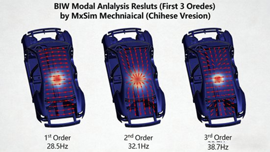
- calculate the first six modal frequencies and mode shapes
- compare results with Nastran and keep error within 5%
The target values were:
- bending stiffness ≥ 28,000 N/mm
- torsional stiffness ≥ 22,000 N·m/deg
These are standard but important targets because body stiffness and mode behavior affect handling, NVH, and overall structural performance.
Model Preparation
The CATIA model was imported into MxSim Mechanical. The preprocessing step cleaned defects such as:
- overlapping surfaces
- sharp corners
- tiny features
For meshing:
- aluminum cover parts used midsurface extraction
- steel frame parts used solid elements
- global mesh size was 5 mm
- total element count was about 1.2 million
- total node count was about 650,000
- mesh pass rate was at least 95%
- minimum Jacobian was at least 0.7
These details show that the case was handled as an engineering-grade full model, not a small demonstration model.
Connection Modeling
The report says the BIW model used:
- 1,800 spot weld elements
- seam weld elements for key welds, with total weld length of about 35 m
- rubber bushing elements at suspension mounting points
- multipoint constraints to describe motion relationships between flexible and rigid regions
This is a strong example of why automotive-specific connection functions matter.
Boundary Conditions and Loads
For bending stiffness:
- front suspension mounting points were fixed
- rear suspension mounting points released longitudinal freedom
- a distributed load of 10,000 N was applied at the seat cross-member region
For torsional stiffness:
- left-front and right-rear wheel points were fixed
- right-front and left-rear wheel points received opposite torque
- total torque was 2,000 N·m
For modal analysis:
- free boundary conditions were used
- the first six modal frequencies and mode shapes were solved
Solving and Result Review
With GPU acceleration enabled:
- bending and torsion solve time was about 45 minutes
- modal solve time was about 30 minutes
Post-processing produced:
- stress contour plots
- deformation contour plots
- modal shape plots
The results pointed to stress concentration areas in:
- the lower B-pillar
- floor cross members
Engineering Results
The final BIW results were:
- bending stiffness: 29,200 N/mm
- torsional stiffness: 23,500 N·m/deg
The first six modal frequencies were:
- 28.5 Hz
- 32.1 Hz
- 38.7 Hz
- 45.3 Hz
- 51.2 Hz
- 58.6 Hz
The report says all were outside problematic resonance ranges.
When compared with Nastran:
- error stayed within 3.8%
Based on the analysis, engineers reinforced:
- the lower B-pillar
- the floor cross members
After that change:
- bending stiffness increased by 8%
- torsional stiffness increased by 6%
- modal frequencies stayed nearly unchanged
Application Scenario 2: Battery Pack Thermal-Structural Coupling
The second case covers a pure electric SUV battery pack using prismatic ternary lithium cells with total capacity of 72 kWh.
Engineering Requirements
The battery pack needed to meet three goals:
- simulate temperature distribution during 1C fast charging over 1.5 hours
- confirm that:
- maximum enclosure stress stayed at or below 150 MPa
- maximum deformation stayed at or below 0.5 mm
- verify lifting lug safety under combined gravity and thermal stress
This is a classic EV problem because temperature rise changes structural stress distribution.
Model Simplification and Meshing
The CATIA model was simplified by removing parts not needed for the main simulation, such as:
- busbars
- electrical details
- fine cooling-channel features
The retained main structures were:
- battery modules
- enclosure
- lifting lugs
Meshing used solid elements with:
- 3 mm mesh size for modules
- 4 mm mesh size for enclosure and lifting lugs
- total element count of about 800,000
- local refinement near stress concentration zones, especially around lifting lugs
Material Properties and Thermal Boundary Conditions
Battery module thermal properties were set as:
- specific heat capacity: 1000 J/(kg·°C)
- thermal conductivity: 15 W/(m·°C)
The enclosure and lifting lugs used 6061-T6 aluminum alloy with:
- elastic modulus: 70 GPa
- Poisson’s ratio: 0.33
- yield strength: 276 MPa
Environmental settings were:
- ambient temperature: 25°C
- convection heat transfer coefficient: 15 W/(m²·°C)
Loads and Coupled Solve Process
The thermal load was defined as a volumetric heat source in the battery modules:
- 2000 W/m³
This represented heat generation during fast charging.
The structural load included:
- battery pack self-weight
- total pack mass of 520 kg
- constraints at the lifting lug region
The report says the coupled solution used a sequential process:
- solve the thermal field
- apply the temperature field as a structural load
- solve for thermal stress and deformation
CPU/GPU heterogeneous parallel solving was used, and total solve time was about 60 minutes.
Engineering Results

At the end of fast charging:
- maximum battery pack temperature reached 58°C
- the hottest area was near the center of the module region
- temperature distribution remained acceptable for the design target
Structural results were:
- maximum enclosure stress: 128 MPa
- maximum deformation: 0.32 mm
- maximum lifting lug stress: 142 MPa
All results met the stated limits.
The report also states that comparison with test data gave:
- temperature error within 4%
- stress error within 5%
Then the cooling channel layout was improved. After that:
- peak temperature dropped to 52°C
- thermal stress fell by 15%
That improved both thermal stability and structural safety.
Application Scenario 3: Chassis Subframe Topology Optimization
The third case covers a steel chassis subframe for a fuel vehicle.
Engineering Requirements
The task was to reduce weight by more than 10% while keeping:
- maximum stress at or below 200 MPa
- bending stiffness at or above 15,000 N/mm
- torsional stiffness at or above 8,000 N·m/deg
The design also needed to respect manufacturing limits such as casting rules and wall thickness constraints, and it had to avoid resonance problems after optimization.
Initial Model and Material Setup
The original CATIA model was cleaned and meshed with solid elements.
- total elements: about 500,000
Material was Q355B steel with:
- elastic modulus: 206 GPa
- Poisson’s ratio: 0.3
- yield strength: 355 MPa
Loads and Boundary Conditions
The simulation fixed the connection points between the subframe and body.
Loads at suspension mounting points were:
- 2000 N vertical load per point
- 1500 N horizontal load per point
These settings represented real working loads transferred into the subframe.
Topology Optimization Setup
The optimization target was minimum compliance, which means maximum stiffness under a mass limit.
The setup included:
- mass reduction target of more than 10%
- minimum wall thickness of 3 mm
- no hollow structures
- preserved connection holes
- preserved mounting surfaces
- optimization applied to the main subframe body region
This is important because engineering optimization has to protect functional areas while changing the rest.
Reconstruction and Validation
The report states that the topology run took about 30 minutes. Engineers then used the result cloud plot to rebuild the shape in CAD and ran validation again on the reconstructed design.
Engineering Results
The final design achieved:
- 12.3% weight reduction
- mass reduced from 28 kg to 24.5 kg
Performance after redesign was:
- maximum stress: 186 MPa
- bending stiffness: 16,200 N/mm
- torsional stiffness: 8,800 N·m/deg
The first six modal frequencies were:
- 42.3 Hz
- 48.7 Hz
- 55.1 Hz
- 62.4 Hz
- 68.9 Hz
- 75.2 Hz
Compared with the original structure:
- stiffness increased by 8%
- stress distribution became more even
- the design remained suitable for casting production
How MxSim Mechanical Fits into the Automotive Development Toolchain
The report places MxSim Mechanical inside a closed-loop engineering process:
CAD modeling → meshing → simulation → optimization → test verification
It supports direct integration with mainstream CAD tools such as:
- CATIA
- UG / NX
- Creo
It also supports FE file exchange through:
- BDF
- INP
- FEM
The report adds that it can work with professional meshing flows such as HyperMesh-style preprocessing. It also supports comparison between simulation data and test data, which helps teams refine models and improve result trust.
Another important point is PLM integration. The report says simulation tasks and result data can be transferred into PLM systems for:
- unified data management
- process traceability
- enterprise workflow fit
That matters a lot in larger engineering organizations.
How It Compares with International CAE Tools
The report compares MxSim Mechanical with tools such as:
- Nastran
- Abaqus
- ANSYS Mechanical
The main points raised are:
- independent core technology
- full Chinese localization
- lower procurement and maintenance cost
- stronger fit for domestic workflows
- support for domestic CPU and GPU hardware
- built-in automotive-oriented modeling features
The report also states that the software purchase and maintenance cost can be about one-third to one-half of international tools. It presents this as one reason domestic OEMs may view MxSim Mechanical as a practical alternative for structural CAE work.
The source material also describes the product as covering about 90% of common Nastran-style structural workflow functions, which gives a rough idea of where it sits in the market.
Top 5 Frequently Asked Questions About MxSim Mechanical
1. How does MxSim Mechanical compare with mainstream international CAE tools such as Nastran, Abaqus, or ANSYS?
Short answer: It covers many of the same structural tasks and is often evaluated as a domestic alternative for common automotive structural workflows.
MxSim Mechanical is presented as a large-scale structural simulation platform comparable to MSC Nastran, Abaqus Implicit, and ANSYS Mechanical for many engineering tasks. The report and related product material describe support for linear and nonlinear structural analysis, modal analysis, contact modeling, and topology optimization.
The main differences often mentioned are:
- independently developed solver architecture
- lower cost
- full Chinese localization
- better fit for domestic deployment
- support for domestic hardware environments
The source material also says it covers about 90% of typical Nastran-style structural workflow functions.
2. What is the low-order high-accuracy element algorithm, and why is it important?
Short answer: It helps engineers get better accuracy from low-order meshes without giving up speed.
Traditional low-order elements are efficient, but their accuracy may be limited in difficult structural models. MxSim Mechanical uses a modified low-order high-accuracy formulation that, according to the report, improves accuracy by more than 50% and cuts solve time by about 5 times in representative cases.
This is especially useful for:
- BIW thin-walled structures
- battery housings
- large assembly models where mesh count and compute time are tight limits
3. What types of engineering analyses can MxSim Mechanical perform?
Short answer: It covers most of the structural and coupled analyses needed in automotive vehicle development.
The report says the software supports:
- linear statics
- nonlinear analysis
- modal analysis
- buckling
- transient response
- frequency response
- random vibration
- response spectrum analysis
- thermal analysis
- thermal-structural coupling
- acoustic-structural coupling
- rigid-flexible multibody dynamics
- topology optimization
In automotive work, that supports tasks such as:
- BIW stiffness and modal development
- chassis structural design
- battery pack thermal-structural simulation
- NVH-related structural response
- lightweight optimization
4. Can MxSim Mechanical integrate with existing automotive engineering toolchains?
Short answer: Yes, it is built to work inside a broader CAD-CAE-PLM flow.
The report says the software supports import from:
- CATIA
- Creo
- UG / NX
It also supports FE file formats such as:
- BDF
- INP
- FEM
For automation and workflow setup, it includes:
- Python interfaces
- C++ interfaces
- parameterized workflows
- automatic load application
- automatic report generation
The report also mentions links to test correlation work and PLM data management.
5. What hardware environments and computing architectures does MxSim Mechanical support?
Short answer: It supports CPU and GPU computing for large engineering models and can work with domestic hardware platforms.
The report says MxSim Mechanical supports:
- CPU parallel solving
- GPU heterogeneous acceleration
- out-of-core computation
- compatibility with domestic processors such as Kunpeng and Loongson
It also gives examples of large automotive model solving, including:
- a 1.5 million-element BIW modal case
- 40% faster solution time under 8-core GPU acceleration
up to 210 times speed improvement in a 4-GPU AMLS setup
