

< Back to Automotive Simulation Toolchain
Direct answer:
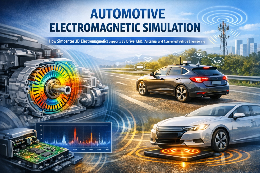
Automotive electromagnetic simulation helps engineers predict magnetic fields, losses, electromagnetic interference, antenna performance, and coupling effects before physical prototypes are built. In the case of Simcenter 3D Electromagnetics, the value lies in one integrated toolchain that supports low-frequency motor and power-electronics analysis, high-frequency EMC and antenna simulation, and multiphysics workflows across modern vehicle development. Siemens presents Simcenter as an integrated CAE environment spanning electromagnetics, structures, thermal, and other physics domains. (Siemens Digital Industries Software)
- Simcenter 3D Electromagnetics is best understood as an automotive electromagnetic toolchain, not a standalone solver.
- It covers low-frequency use cases like e-motors, inverters, transformers, and sensors, and high-frequency use cases like EMC, antennas, V2X, and wireless communication. (Siemens Digital Industries Software)
- Its automotive value is built around shorter development cycles, lower prototype cost, and better product quality.
- The strongest vehicle applications are EV drive systems, automotive EMC compliance, vehicle antenna placement, and wireless charging / connected-vehicle analysis.
- It becomes more powerful when tied to NX CAD, Teamcenter, multiphysics simulation, and workflow automation. (Siemens Digital Industries Software)
Modern vehicles do not suffer from one isolated electromagnetic problem at a time. A traction motor creates electromagnetic force ripple and heat. A switching inverter becomes a strong interference source. A wire harness acts like an unintended coupling path. A roof antenna behaves one way in free space and another way when mounted on a real body-in-white. That is why automotive teams are shifting from test-led troubleshooting to simulation-driven design earlier in the development cycle.
Author: Johnny Liu, CEO at Dowway Vehicle
Last updated: March 16, 2026
Primary keyword: automotive electromagnetic simulation
Article type: Cluster page
Industry note: This article is written for engineering and product-development audiences. Final regulatory, certification, and compliance decisions must still be verified through the applicable physical tests and standards.
- Why is automotive electromagnetic simulation becoming critical in modern vehicle development?
- What is Simcenter 3D Electromagnetics?
- How is the Simcenter 3D Electromagnetics toolchain structured?
- What core technical capabilities make the toolchain useful for automotive engineers?
- How does Simcenter 3D Electromagnetics support EV drive system development?
- How does Simcenter 3D Electromagnetics help with automotive EMC compliance and interference suppression?
- How does Simcenter 3D Electromagnetics improve vehicle antenna layout and communication performance?
- How does the toolchain support wireless charging and connected-vehicle electromagnetic scenarios?
- How does multiphysics coupling improve real-world automotive accuracy?
- How does automation and customization improve enterprise automotive workflows?
- What practical engineering value does Simcenter 3D Electromagnetics deliver to automotive programs?
- What should automotive teams evaluate before adopting an electromagnetic toolchain?
- Why are automotive companies shifting from prototype-driven testing to simulation-driven design?
- What is the future of automotive electromagnetic simulation?
- Final takeaway
- FAQs
- 1. What automotive engineering problems can Simcenter 3D Electromagnetics solve?
- 2. How does Simcenter 3D Electromagnetics support electric vehicle powertrain development?
- 3. Can Simcenter 3D Electromagnetics perform both low-frequency and high-frequency simulations?
- 4. How does Simcenter integrate with automotive development workflows?
- 5. Why are automotive companies adopting electromagnetic simulation earlier in the design process?
- Author bio
Why is automotive electromagnetic simulation becoming critical in modern vehicle development?
Automotive electromagnetic simulation is becoming critical because the vehicle electrical environment is getting denser, faster, and more strongly coupled. The shift to electrification, intelligence, and connectivity means electromagnetic performance now affects not only efficiency, but also safety, reliability, comfort, sensor integrity, and communication stability.
Your source report correctly frames the industry context. Vehicle platforms are moving rapidly toward:
- electrification: battery electric and hybrid architectures
- intelligence: ADAS and advanced electronic control systems
- connectivity: V2X, telematics, 5G, and vehicle networking
- wireless functionality: antenna-dense platforms and wireless charging scenarios
This creates a vehicle electromagnetic environment that is increasingly:
- high-frequency
- multi-source
- strongly coupled
In practical engineering terms, that means several recurring problems:
- electromagnetic interference from electric drive systems disturbing onboard electronics
- EMC failures in ECUs, sensors, and harnesses
- antenna radiation performance changing after installation on the vehicle
- communication quality dropping because of coupling or poor placement
- wireless charging leakage that must remain within human-safety limits
- electromagnetic force and loss behavior reducing efficiency and increasing NVH
The traditional development model—build hardware, run tests, find issues, modify design, and repeat—still has a place, but it is too slow and too expensive to remain the primary strategy. Siemens positions Simcenter as an integrated simulation environment that helps move product development toward earlier prediction, cross-domain analysis, and digital-twin-enabled engineering. (resources.sw.siemens.com)
What is Simcenter 3D Electromagnetics?
Simcenter 3D Electromagnetics is the electromagnetics capability within the broader Simcenter 3D simulation platform. It is designed to support electromagnetic analysis inside the same environment used for other engineering disciplines, including structures, thermal analysis, acoustics, and system-level simulation. Siemens describes Simcenter 3D as a unified and fully integrated CAE environment for complex, multidisciplinary product-performance engineering. (Siemens Digital Industries Software)
In automotive engineering, that matters because electromagnetic problems are rarely independent from:
- geometry and packaging
- thermal conditions
- structural vibration
- harness layout
- system-level operating behavior
- lifecycle data management
Based on your report, Simcenter 3D Electromagnetics functions as a full-process automotive R&D toolchain rather than a single-purpose field solver. It supports:
- part-level simulation for motors, magnets, coils, shielding structures, antennas, transformers, and sensors
- subsystem-level analysis for inverters, ECUs, wire harnesses, cable paths, and communication assemblies
- vehicle-level evaluation for EMC, antenna installation effects, and full-platform electromagnetic interactions
It is especially valuable because it supports a design–simulation–iteration loop in which CAD changes can be reflected quickly in the simulation model, reducing manual rebuild work and enabling a tighter engineering workflow. Siemens also highlights integration with the broader digital engineering ecosystem, including Teamcenter-based simulation data management and workflow connectivity across other Simcenter solutions. (Siemens Digital Industries Software)
How is the Simcenter 3D Electromagnetics toolchain structured?
The report defines the toolchain through a three-layer architecture, and that is the clearest way to explain its engineering logic.
Foundation layer: geometry, materials, and preprocessing
At the bottom of the stack is the model foundation. According to your report, this layer is based on the NX CAD kernel and Parasolid geometry engine, with support for importing mainstream automotive CAD models such as CATIA, UG/NX, and SolidWorks.
This layer supports:
- direct import of vehicle and component CAD
- geometry simplification
- geometry repair
- electromagnetic-model preparation
- mesh generation
That sounds basic, but it is not. In real automotive projects, raw CAD is often not analysis-ready. Engineers need to remove redundant features such as small holes, fillets, and minor chamfers while preserving the structures that actually control electromagnetic behavior, including:
- windings
- air gaps
- iron cores
- permanent magnets
- shielding features
- enclosure seams
- antenna radiating structures
The report also notes that the toolchain includes an automotive-oriented material library with more than 300 commonly used materials, covering parameters such as:
- magnetic permeability
- electrical conductivity
- dielectric constant
It also supports custom material definition to match actual automotive parts such as cores, windings, shielding materials, and plastics.
Core simulation layer: low-frequency and high-frequency electromagnetics
The core simulation layer is divided into two major modules:
- Low Frequency EM
- High Frequency EM
This split aligns well with real automotive needs.
The low-frequency module focuses on components such as:
- electric drive systems
- transformers
- sensors
- electromechanical components
It supports simulation types including:
- static magnetic field
- harmonic magnetic field
- transient magnetic field
The high-frequency module focuses on:
- vehicle antennas
- EMC / EMI
- wireless communication
- radiation and scattering
- coupling behavior in vehicle systems
Siemens’ official material confirms that Simcenter 3D for electromagnetics integrates low-frequency solvers and a variety of high-frequency solvers for wave-propagation phenomena. Siemens also highlights time- and frequency-based methods, finite-element and boundary-element capabilities, and dedicated EMC and connectivity use cases. (Siemens Digital Industries Software)
Application layer: automotive engineering solutions
The application layer turns the platform into an automotive workflow. Based on your report, it supports scenario-driven engineering for:
- EV drive-system electromagnetic optimization
- vehicle EMC compliance analysis
- antenna layout optimization
- wireless charging electromagnetic simulation
- connected-vehicle communication analysis
- multiphysics workflows involving thermal and structural effects
This is also where Simcenter 3D Electromagnetics becomes relevant to broader automotive digital engineering. Siemens positions Simcenter integration solutions around connecting simulation domains, optimization, and digital-thread workflows rather than keeping CAE siloed. (Siemens Digital Industries Software)
What core technical capabilities make the toolchain useful for automotive engineers?
The toolchain stands out because it combines frequency-range breadth, solver flexibility, integration, multiphysics capability, and automation in one engineering environment.
Full-frequency coverage
Your report states that the toolchain supports electromagnetic simulation from 1 Hz to 100 GHz. That is a strong way to frame its automotive value because vehicle programs span both:
- low-frequency electromagnetic problems such as motors, inverters, and sensors
- high-frequency electromagnetic problems such as antennas, V2X communication, and EMC
That single-platform range is especially important in modern vehicles, where different teams may need to study motor fields in the same overall program that is also solving antenna siting or EMI issues.
High-accuracy simulation algorithms
The report names several numerical methods:
- FEM
- BEM
- FDTD
It also emphasizes adaptive solver choice depending on the problem.
That is important because a low-frequency motor saturation study and a high-frequency radiating enclosure problem do not benefit from exactly the same numerical treatment. Siemens likewise describes a portfolio of specialized solvers covering time and frequency domains, linear and nonlinear behavior, and both finite-element and boundary-element approaches. (Siemens Digital Industries Software)
Seamless integration with automotive development workflows
A major advantage described in your report is the ability to connect simulation directly to the development process. When CAD changes, simulation models can be updated without a full remesh-and-rebuild cycle from scratch. The broader Siemens ecosystem also supports simulation data management and connected workflows through Teamcenter and related Simcenter integration solutions. (Siemens Digital Industries Software)
Multiphysics coupling
Your report highlights one of the most important engineering strengths of the platform: multiphysics coupling.
It specifically points to:
- electromagnetic–thermal coupling, such as winding heating and temperature rise caused by electromagnetic losses
- electromagnetic–structural coupling, such as vibration and noise caused by electromagnetic force
This matters because purely electromagnetic results can be misleading if they are separated from the thermal and structural conditions that shape real-world behavior.
Automation and customization
The report also notes support for automation through Journal files and scripting with C# and Python, enabling:
- automated simulation workflows
- batch studies
- company-specific templates
- standardized engineering processes
This is especially useful for automotive companies that need to run repeated design variants, evaluate multiple packaging alternatives, or enforce internal simulation standards at scale. Siemens separately highlights workflow automation and design-space exploration through Simcenter HEEDS and broader integration solutions. (Siemens Digital Industries Software)
How does Simcenter 3D Electromagnetics support EV drive system development?
Simcenter 3D Electromagnetics supports EV drive-system development by enabling detailed electromagnetic analysis of the motor, inverter, and related electromechanical subsystems early in the design process. That helps engineering teams optimize efficiency, power density, losses, NVH behavior, and electromagnetic compatibility before physical testing.
The report correctly identifies the electric drive system as a core component in new-energy vehicles. Its electromagnetic performance directly affects:
- motor efficiency
- power density
- torque and force behavior
- vibration and acoustic response
- inverter EMI behavior
- overall system integration quality
Why the e-drive system is a central electromagnetic problem
In EVs and hybrids, the drive unit is no longer just a mechanical power source. It is an electromagnetic, thermal, structural, and controls problem at the same time. The electromagnetic design of the machine influences:
- torque production
- local magnetic saturation
- rotor and stator forces
- iron loss and copper loss
- thermal loading
- force ripple that can produce noise or vibration
Even small design choices—slot/pole combinations, magnet geometry, winding topology, current excitation, or air-gap treatment—can materially change performance.
Typical EV drive simulation workflow
Your report lays out a practical engineering workflow that should be preserved in full:
1. Geometry modeling and preprocessing
The motor and inverter CAD models are imported into the environment. Engineers simplify redundant details such as chamfers or tiny holes while preserving electromagnetically critical structures including:
- windings
- iron core
- permanent magnets
- air gap
- conductive paths
2. Material and boundary-condition setup
Engineers select material parameters from the built-in library or define custom materials for:
- core materials
- conductor materials
- permanent magnets
- insulation
- shielding materials
Boundary conditions and operating parameters are then defined, including:
- winding currents
- magnetic flux density of permanent magnets
- speed
- load
- nonlinear magnetic properties
- hysteresis effects where needed
3. Mesh generation
The report emphasizes adaptive meshing, with local mesh refinement in critical regions such as:
- the motor air gap
- windings
- localized field concentration areas
This helps maintain simulation accuracy without making the overall computation unnecessarily expensive.
4. Solve setup
Depending on the design question, the workflow can use:
- static magnetic analysis
- harmonic magnetic analysis
- transient magnetic analysis
These solve types are used to calculate key outputs such as:
- magnetic field distribution
- electromagnetic force
- iron loss
- copper loss
- back electromotive force
- local flux density distribution
5. Result analysis and design optimization
The results are then visualized and interpreted through post-processing tools. Engineers can locate weak points such as:
- excessive local flux density in the core
- large winding loss
- uneven air-gap flux distribution
- high force ripple
- efficiency-limiting design features
Optimization may involve changes to:
- slot/pole combination
- winding layout
- permanent-magnet dimensions
- magnetization direction
- structural layout of the machine
Engineering case from the report
Your report includes a detailed and valuable example. In one EV development case involving a permanent magnet synchronous motor, simulation revealed nonuniform air-gap flux distribution that caused excessive electromagnetic force pulsation and NVH issues.
The reported design changes included:
- changing the slot/pole combination from 24 slots / 8 poles to 36 slots / 12 poles
- adjusting the magnetization direction
- adjusting the thickness of the permanent magnets
- optimizing the winding layout
The reported outcomes were:
- 35% reduction in electromagnetic force ripple
- 4 dB(A) reduction in motor noise
- 2.3% improvement in motor efficiency
That example captures the core value of simulation-led e-drive design: not just observing fields, but converting insight into measurable design improvement.
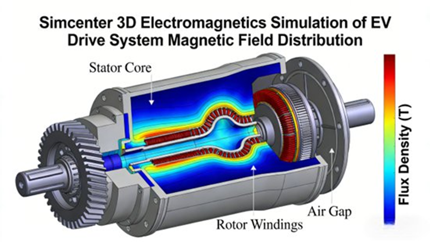
Figure placeholder:
Fig. 1. Simcenter 3D Electromagnetics Simulation of EV Drive System Magnetic Field Distribution (Contour Plot of Flux Density)
How does Simcenter 3D Electromagnetics help with automotive EMC compliance and interference suppression?
Simcenter 3D Electromagnetics helps with automotive EMC by allowing engineers to model radiated and conducted effects before formal testing, identify dominant coupling paths, and optimize shielding, grounding, enclosure design, and harness routing earlier in the design cycle.
This is increasingly important because modern vehicles carry many electronic devices:
- ADAS sensors
- vehicle infotainment systems
- V2X modules
- telematics units
- cameras
- radar
- ECUs
- TPMS modules
As the report notes, automotive products must satisfy EMC requirements such as GB/T 21437 and CISPR 25. IEC states that CISPR 25:2021 contains limits and measurement procedures for radio disturbances in the frequency range from 150 kHz to 5,925 MHz for protecting onboard receivers. (webstore.iec.ch)
EMC scenarios covered in the workflow
Your report identifies the key EMC categories:
- Radiated Emission (RE)
- Conducted Emission (CE)
- Radiated Susceptibility / Immunity (RS)
- Conducted Susceptibility / Immunity (CS)
That is a useful structure because it mirrors how vehicle EMC teams assess both source behavior and victim robustness.
Typical automotive EMC simulation workflow
1. Build a vehicle or subsystem electromagnetic model
Engineers import the full vehicle or a relevant subsystem, such as:
- ECU enclosure
- sensor module
- wiring harness
- shielding bracket
- chassis/vehicle body structures
The model must capture the elements most relevant to EMC behavior, especially:
- harness routing
- shielding structures
- enclosure seams
- ground paths
- proximity between aggressors and victims
The report specifically notes that wire-harness data generated in Capital can be imported for more accurate 3D routing and cable/property representation. Siemens’ solution guide likewise notes direct wire-harness import from Capital software, including automatic 3D path generation and assignment of cable properties for EMC analysis. (resources.sw.siemens.com)
2. Define noise sources and sensitive devices
Engineers specify aggressors such as:
- inverter
- motor
- vehicle radar
- switching power electronics
They also define sensitive devices such as:
- GPS antenna
- camera
- TPMS sensor
- low-noise control modules
3. Run high-frequency electromagnetic analysis
The solver is used to calculate:
- radiation distribution
- coupling intensity along harnesses
- exposure level at sensitive devices
- field leakage from enclosures
- resonance or emission peaks over frequency
4. Optimize EMC mitigation measures
Based on the findings, engineers can improve:
- shielding structure
- shielding material
- conductive sealing
- cable spacing
- routing path
- grounding design
- enclosure leakage control
Engineering cases from the report
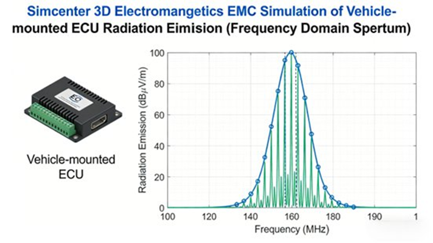
ECU radiation-emission case
In one case, an automotive ECU exceeded radiated-emission limits in the 100 MHz to 500 MHz frequency range. Simulation showed that shielding performance was insufficient because radiation from the internal PCB leaked through enclosure gaps.
The reported optimization steps included:
- changing the enclosure material from ordinary aluminum alloy to conductive aluminum alloy
- adding conductive adhesive sealing at the enclosure gaps
- improving the PCB grounding strategy
The result was a 20 dBμV/m reduction in radiated emission, allowing the ECU to satisfy the target CISPR 25 requirement described in the report.
TPMS interference-immunity case
The report also describes a tire-pressure sensor case in which simulation compared:
- an unshielded harness configuration
- a shielded harness configuration
By optimizing the harness shielding design, the sensor’s immunity performance improved by more than 30%.
These cases matter because they show that EMC failures are often caused by design details—gaps, routing, shielding transitions, and grounding—not just by abstract field strength.
Figure placeholder:
Fig. 2. Simcenter 3D Electromagnetics EMC Simulation of Vehicle-mounted ECU Radiation Emission (Frequency Domain Spectrum)
How does Simcenter 3D Electromagnetics improve vehicle antenna layout and communication performance?
Simcenter 3D Electromagnetics improves antenna engineering by letting teams simulate radiation performance, installation effects, and electromagnetic coupling in the context of the full vehicle. That helps optimize antenna location, spacing, and orientation before expensive vehicle-level RF troubleshooting begins.
Vehicle antennas are central to:
- navigation
- telematics
- connected services
- 5G communication
- V2X communication
- broadcast reception
But in modern vehicles, an antenna is not a standalone RF component. Its performance is shaped by:
- body geometry
- glass
- mounting structures
- nearby electronics
- other antennas
- cable routing
- installation orientation
Typical vehicle antenna workflow
1. Create the antenna model
The report notes that engineers can:
- import antenna CAD models
- use built-in antenna templates such as dipole or patch-style models
- model equivalent antenna behavior using electromagnetic source representations
Relevant antenna types in the report include:
- GPS antennas
- 5G antennas
- V2X antennas
2. Build the full vehicle environment
The whole-vehicle model is imported, preserving the structures that influence electromagnetic radiation, including:
- body surfaces
- windows
- installed electronics
- nearby conductive structures
Noncritical geometry is simplified to improve solve efficiency.
3. Run high-frequency analysis
Engineers evaluate outputs such as:
- radiation pattern
- gain
- VSWR
- coupling level with other antennas
- interaction with nearby electronic modules
4. Optimize antenna placement
Simulation then guides changes to:
- antenna location
- spacing between antennas
- orientation
- mounting strategy
Engineering case from the report
Your source report presents a specific case involving coupling between a vehicle 5G antenna and a GPS antenna, which caused weak GPS signal strength and reduced positioning accuracy.
Simulation showed that:
- the spacing between the antennas was less than 30 cm
- their radiation directions overlapped significantly
The optimization steps were:
- increasing the spacing to 50 cm
- adjusting antenna orientation
The reported results were:
- 40% reduction in electromagnetic coupling interference
- 15 dB increase in GPS signal strength
- simulation-to-test deviation of less than 3 dB
That last point is especially important. For automotive engineering teams, credibility depends not only on simulation speed, but on acceptable correlation between simulation and physical testing.
The report also notes that the tool can simulate antenna radiation performance under different vehicle body attitudes, helping ensure stable communication performance during real vehicle operation.
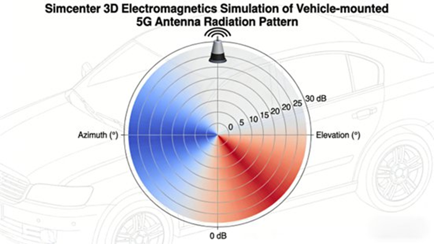
Figure placeholder:
Fig. 3. Simcenter 3D Electromagnetics Simulation of Vehicle-mounted 5G Antenna Radiation Pattern (3D Polar Plot)
How does the toolchain support wireless charging and connected-vehicle electromagnetic scenarios?
The same toolchain supports both low-frequency power-transfer problems and high-frequency communication problems, which is increasingly important as vehicles add wireless charging and connected-vehicle technologies.
The report specifically highlights wireless charging and vehicle networking / V2X as part of the changing automotive electromagnetic environment.
Wireless charging
Wireless charging creates two linked engineering challenges:
- maintaining efficient electromagnetic power transfer
- controlling electromagnetic leakage so it meets human-safety requirements
Because wireless power systems generate significant electromagnetic fields, engineers need simulation not only for transfer performance but also for exposure and leakage control.
Connected-vehicle communication
Connected vehicles create a different challenge. V2X, telematics, GPS, and 5G systems all operate in frequency bands where antenna performance, body effects, and coupling strongly affect communication quality.
This is why a full-spectrum electromagnetic toolchain matters: low-frequency and high-frequency automotive problems are increasingly part of the same platform program.
How does multiphysics coupling improve real-world automotive accuracy?
Multiphysics coupling improves accuracy because electromagnetic behavior in vehicles is rarely independent from temperature, structure, vibration, or system-level operating conditions. A pure EM result can be useful, but a coupled result is usually closer to what the product will do in service.
Your report specifically calls out two coupling modes.
Electromagnetic–thermal coupling
This is important in components such as:
- electric motors
- windings
- power electronics
- loss-producing magnetic devices
Electromagnetic losses generate heat. Heat changes material properties and affects performance. The report specifically mentions:
- winding heating
- temperature rise caused by electromagnetic losses
That makes EM-thermal coupling necessary when design decisions must reflect real operating temperatures rather than ideal lab assumptions.
Electromagnetic–structural coupling
This is important when electromagnetic force causes:
- vibration
- noise
- deformation-related effects in operation
The report specifically points to motor vibration and noise generated by electromagnetic force. This is particularly relevant in EVs, where the absence of an engine makes electric-drive noise more noticeable.
Why single-physics analysis is often insufficient
A single-domain simulation can miss important behavior such as:
- a motor design that looks efficient electromagnetically but runs too hot
- a force pattern that causes structural vibration and acoustic issues
- an enclosure that appears acceptable electrically but leaks once mechanical details are included
That is why the report treats multiphysics capability as a core technical differentiator rather than a secondary add-on.
How does automation and customization improve enterprise automotive workflows?
Automation makes the toolchain scalable. In automotive development, engineers do not solve one clean academic model once. They run repeated studies across product variants, operating points, packaging options, and design revisions.
The report notes support for:
- Journal-based automation
- programming through C#
- programming through Python
- reusable custom templates
- company-standardized simulation processes
This is valuable for several reasons:
- repeated simulation steps can be automated
- batch evaluation of variants becomes practical
- internal modeling rules can be standardized
- engineering quality becomes more repeatable
- turnaround time is reduced across product lines
Siemens also emphasizes workflow automation and design exploration in its Simcenter integration portfolio and HEEDS offering, which aligns with the report’s focus on enterprise-scale efficiency rather than isolated manual simulation. (Siemens Digital Industries Software)
What practical engineering value does Simcenter 3D Electromagnetics deliver to automotive programs?
The report summarizes the engineering value in three themes: cost reduction, efficiency improvement, and quality improvement. That framework is accurate and strong for a cluster page because it translates technical capability into program-level outcomes.
1. Shorter development cycles
By moving electromagnetic simulation into early design, teams can detect issues before late validation stages. The report states that:
- e-drive electromagnetic optimization cycles can be shortened by more than 40%
- EMC remediation cycles can be shortened by more than 50%
It also cites a DENSO case showing that integrated NX and Simcenter workflows with automation reduced component simulation time by 80%, which aligns with Siemens’ case-study material. (Siemens Digital Industries Software)
2. Lower development cost
The report states that simulation reduces the number of physical prototypes, test iterations, and redesign cycles. It also notes that simulation-driven optimization can reduce material consumption, such as:
- optimizing motor core dimensions
- reducing unnecessary shielding material usage
The report estimates that automotive electromagnetic R&D costs can be reduced by 30% to 50%.
3. Better product quality
The report ties high-accuracy simulation to better product outcomes, including:
- lower EMC failure rates
- higher motor efficiency
- better communication performance
- better NVH behavior
- improved safety, reliability, and comfort
It specifically notes outcomes such as:
- reducing automotive electronic EMC nonconformance rates by more than 60%
- increasing motor efficiency by 2% to 5%
4. Support for digital R&D transformation
This is one of the most strategic points in the report. Simcenter 3D Electromagnetics supports a digital-twin-oriented workflow in which design, simulation, testing, and optimization are linked in a closed loop.
The report argues that this helps automotive companies shift toward simulation-driven design and integrate electromagnetic development into broader digital R&D systems. Siemens’ Simcenter integration positioning similarly emphasizes connected simulation, digital-thread integration, and multidisciplinary engineering workflows. (Siemens Digital Industries Software)
What should automotive teams evaluate before adopting an electromagnetic toolchain?
Automotive teams should evaluate not only solver power, but also how well the toolchain fits real development workflows. The right question is not simply whether the software can solve a model. The better question is whether it can support the company’s actual engineering process across repeated vehicle programs.
| Evaluation Area | What the Team Should Check |
| Core use cases | Does the team need motors, EMC, antennas, wireless charging, sensors, or full-vehicle analysis? |
| CAD integration | Can the model remain synchronized with evolving design geometry? |
| Harness workflow | Can wire-harness data be imported and maintained efficiently? |
| Multiphysics | Is EM-only enough, or are thermal and structural couplings required? |
| Automation | Will repeated studies benefit from scripting, templates, and batch workflows? |
| Validation | Can simulation results be compared and calibrated against test results efficiently? |
| Enterprise scale | Can the workflow be standardized across teams and product lines? |
For suppliers and OEMs alike, one of the biggest hidden benefits is standardization. Once templates, model setup rules, and reporting structures are established, electromagnetic simulation becomes a repeatable engineering asset rather than a one-off specialist activity.
Why are automotive companies shifting from prototype-driven testing to simulation-driven design?
Automotive companies are adopting electromagnetic simulation earlier because electrical architectures have become too complex for late-stage troubleshooting alone. EVs, connected cars, advanced driver assistance systems, and wireless functions all create tightly coupled electromagnetic environments that are expensive to debug after hardware is built.
By simulating earlier, engineering teams can:
- identify EMI and EMC risks before hardware testing
- reduce prototype iterations
- shorten development cycles
- improve efficiency and communication performance
- make design decisions with better confidence
That shift is not just a software trend. It is a response to real vehicle complexity.
What is the future of automotive electromagnetic simulation?
The report’s future outlook is strong and should be preserved in full: as vehicles become more electrified, intelligent, and connected, their electromagnetic environments will become even more complex, which will raise the requirement for faster, broader, and more deeply integrated simulation.
The report points specifically to future pressure from:
- ADAS
- autonomous driving
- vehicle-road coordination / V2X
- more complex vehicle electromagnetic environments
It also expects Simcenter 3D Electromagnetics to evolve further in areas such as:
- AI-driven simulation optimization
- deeper multiphysics coupling
- large-scale full-vehicle simulation
- stronger integration with the Siemens digital twin ecosystem
That outlook fits the broader direction Siemens communicates across its Simcenter portfolio, where integration, automation, and multidisciplinary development are core themes. (Siemens Digital Industries Software)
Final takeaway
Simcenter 3D Electromagnetics is not just a point tool for electromagnetic specialists. In the context of automotive engineering, it functions as a full-process electromagnetic simulation toolchain that helps teams move from reactive testing to predictive development.
Based on the source report, its core advantages are:
- full-frequency electromagnetic coverage from low-frequency machine behavior to high-frequency EMC and antenna analysis
- accurate solver support for complex vehicle electromagnetic behavior
- strong integration with CAD and digital development workflows
- multiphysics coupling for more realistic operating-condition simulation
- automation and customization for scalable engineering execution
Its most valuable automotive applications include:
- new-energy vehicle electric-drive simulation and optimization
- vehicle EMC analysis and suppression design
- vehicle antenna placement and communication performance validation
- wireless charging and connected-vehicle electromagnetic studies
And its most important engineering outcomes are:
- reduced cost
- shorter development cycles
- higher product quality
- support for digital R&D transformation
FAQs
1. What automotive engineering problems can Simcenter 3D Electromagnetics solve?
Simcenter 3D Electromagnetics is widely used to simulate and optimize electromagnetic behavior in complex automotive systems. Engineers primarily use it for:
- electric motor and generator design
- electromagnetic compatibility (EMC) and interference (EMI) analysis
- antenna design and placement for vehicle connectivity
- power electronics and energy-conversion performance
- electromechanical component behavior
These capabilities help engineers evaluate system-level electromagnetic phenomena and improve performance, efficiency, and compliance before physical prototypes are built. Siemens describes Simcenter’s electromagnetics portfolio around motor performance, EMC/EMI, connectivity, and wave-propagation use cases, which matches the application scope summarized in your report. (Siemens Digital Industries Software)
2. How does Simcenter 3D Electromagnetics support electric vehicle powertrain development?
In EV development, electromagnetic simulation is critical because electric powertrains generate strong electromagnetic fields that may interfere with sensitive electronics and also determine machine performance.
Simcenter enables engineers to:
- model electric motors, inverters, and power electronics
- predict electromagnetic losses, torque behavior, back EMF, and efficiency
- simulate electromagnetic noise sources produced by switching inverters
- analyze interactions between high-voltage powertrains and low-voltage electronics
This makes it easier to identify EMI and EMC risks early and reduce costly redesign during testing and certification.
3. Can Simcenter 3D Electromagnetics perform both low-frequency and high-frequency simulations?
Yes. One of the major strengths of the platform is its ability to cover a wide electromagnetic spectrum through integrated solvers.
The toolchain includes:
- low-frequency solvers for motors, transformers, sensors, and electromechanical devices
- high-frequency solvers for antenna radiation, wireless communication, scattering, and EMC
- multiple numerical methods such as FEM, boundary-element methods, and time-/frequency-domain approaches
Siemens’ official material confirms this combination of integrated low-frequency and high-frequency electromagnetics capabilities. (Siemens Digital Industries Software)
4. How does Simcenter integrate with automotive development workflows?
Simcenter 3D is part of Siemens’ broader digital engineering ecosystem and integrates directly with connected simulation and engineering workflows. Siemens positions Simcenter 3D as a unified CAE environment and Simcenter integration solutions as part of a broader digital thread that connects simulation domains and data management. (Siemens Digital Industries Software)
This integration allows teams to:
- update simulation models when CAD changes
- connect component-level and system-level simulations
- combine electromagnetic analysis with structural, thermal, and fluid workflows
- support digital-twin-oriented product development
- automate and scale engineering studies
The report also emphasizes continuity with automotive CAD design tools, PLM processes, and enterprise simulation standards.
5. Why are automotive companies adopting electromagnetic simulation earlier in the design process?
The automotive industry is shifting from prototype-driven testing to simulation-driven design because electromagnetic problems are growing more expensive to solve late in the program.
Early electromagnetic simulation helps teams:
- identify EMC and EMI risks before hardware testing
- reduce prototype iterations
- shorten development cycles
- optimize efficiency, NVH, and communication performance
- improve the reliability of electronic and connected systems
In EVs and intelligent connected vehicles, that early simulation step is increasingly becoming essential, not optional.
Author bio
Johnny Liu is the CEO at Dowway Vehicle and writes about automotive engineering, vehicle technology, and simulation-led product development. His focus is on how advanced engineering workflows can help automotive companies improve performance, reduce iteration cost, and build more reliable electric and connected vehicles.
