

< Back to Electrical & Electronic Toolchain
Last updated: March 17, 2026
Author: Johnny Liu, CEO at Dowway Vehicle
Technical review note: For final publication, add a named reviewer such as a Lead E/E Architect, Functional Safety Lead, or Vehicle Network Engineer.
- Why is automotive E/E architecture simulation now essential?
- What is automotive E/E architecture simulation?
- What technical system supports automotive E/E architecture simulation?
- What are the key types of automotive E/E architecture simulation?
- How does architecture topology simulation work?
- Why is bus communication simulation critical?
- How does functional safety simulation support E/E architecture development?
- Why is real-time simulation central to modern E/E architecture validation?
- What is multi-domain co-simulation in automotive E/E architecture?
- What are the main engineering difficulties in automotive E/E architecture simulation?
- How can automotive teams solve these simulation challenges?
- Which simulation tools are most important for automotive E/E architecture development?
- What does real engineering application look like? Two case studies
- Case Study 1: Simulation in centralized E/E architecture development
- Case Study 2: Multi-domain co-simulation in zonal E/E architecture for a new energy vehicle
- What are the future trends in automotive E/E architecture simulation?
- Full engineering takeaway
- Frequently Asked Questions About Automotive E/E Architecture Simulation
- 1. Why is simulation becoming essential for modern automotive E/E architecture development?
- 2. What are the biggest technical challenges in E/E architecture simulation?
- 3. Which simulation tools are most commonly used for automotive E/E architecture development?
- 4. How does simulation support functional safety validation under ISO 26262?
- 5. How will simulation evolve in the era of software-defined vehicles?
- Author Bio
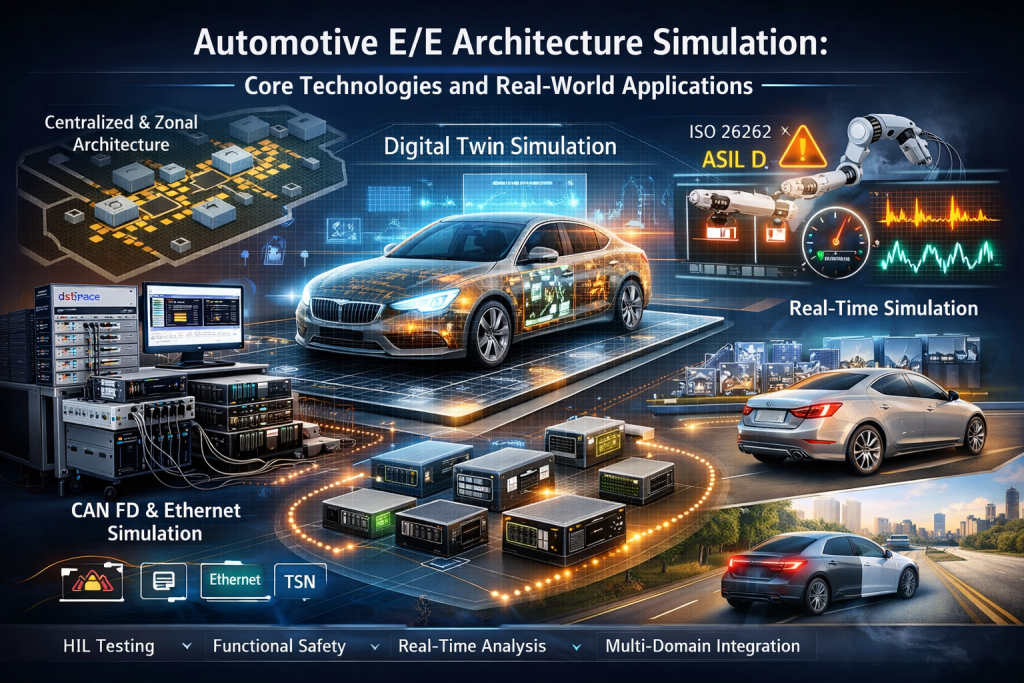
Automotive E/E architecture simulation is the virtual modeling and validation of a vehicle’s electronic and electrical system. It lets engineering teams test architecture design, communication behavior, timing, safety, and cross-domain interaction before full hardware prototypes are built. In software-defined vehicles, this work is now a core part of development rather than a side task.
- Automotive E/E architecture is moving from distributed ECUs to centralized and zonal systems.
- Simulation helps teams verify topology, communication, safety, timing, and cross-domain behavior earlier.
- It supports shift-left validation and reduces late-stage testing cost.
- The technical system has four layers: model, execution, validation, and data management.
- The five key simulation types are topology, bus communication, functional safety, real-time, and multi-domain co-simulation.
- The main engineering problems are model fidelity, tool interoperability, real-time load, and scenario coverage.
- Common tools include Simulink, Simcenter Amesim, Ansys, CANoe, RTaW-Pegase, dSPACE, ETAS LABCAR, and QEMU.
- Future work is moving toward AI-assisted simulation, digital twins, vehicle-cloud simulation, and lightweight models.
Modern vehicles are now built around software, central compute, sensor fusion, connectivity, and continuous updates. That shift has changed the role of E/E architecture. It is no longer just wiring and controller placement. It now shapes how the whole vehicle works, how fast features can be updated, and how safely different systems interact. Because of that, simulation has become one of the main ways to test ideas before they become expensive hardware changes.
Why is automotive E/E architecture simulation now essential?
It is essential because vehicle development has outgrown the old workflow of designing first, building prototypes, then finding issues late in bench testing or vehicle testing. Modern vehicles must support ADAS, automated driving, smart cockpit systems, V2X connectivity, electric powertrains, and a growing number of software-driven functions. All of these depend on a tightly integrated E/E system.
The architecture behind those functions is shifting from distributed control, where many ECUs manage separate functions, to centralized and zonal architectures, where a central computing unit (CCU) works with zonal control units (ZCUs). This reduces ECU count, cuts wiring complexity, and improves software scalability. It also raises the difficulty of integration, timing control, fault handling, safety design, and software coordination.
The report makes a practical point here. Traditional physical testing is expensive and slow. A single full vehicle test program can cost millions of RMB, and bench testing still cannot cover enough conditions early enough. Late-stage fixes become much more expensive once hardware has already been built. Simulation changes that by moving validation earlier, where topology problems, bus congestion, scheduling conflicts, compatibility issues, and fault response gaps can be found before prototype freeze.
This also fits with broader engineering practice. ISO 26262 remains the main functional safety framework for road vehicle E/E systems, and cloud-based virtual validation is becoming more common in software-defined vehicle programs.
What is automotive E/E architecture simulation?
Automotive E/E architecture simulation is the use of a virtual model of the vehicle’s electronic and electrical system to simulate behavior, analyze performance, verify functions, and test faults across development.
At its core, it is the use of digital twin logic in automotive E/E engineering. A virtual version of the real system is built so engineers can model how sensors, ECUs, buses, actuators, and the outside environment interact. This model is then used to:
- verify architecture correctness before physical prototypes
- analyze timing, latency, CPU load, and reliability
- improve network design, architecture layout, and software scheduling
- simulate faults and check safety mechanisms
- support lifecycle testing, diagnostics, and reuse of test assets
The report defines four key traits of E/E architecture simulation:
- System-wide coverage across the sensor–ECU–bus–actuator chain
- Real-time relevance with simulation accuracy close to the real vehicle, ideally within 5%
- Scalability as architectures move from distributed to centralized and zonal forms
- Engineering usefulness through integration with mainstream design and test tools
That combination is what makes simulation useful in actual vehicle programs.
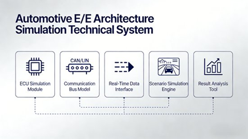
What technical system supports automotive E/E architecture simulation?
The report breaks the technical system into four layers: simulation model layer, simulation execution layer, simulation validation layer, and data management layer. These layers work together to support the full simulation process.
Simulation model layer
This is the base of the whole system. It contains the digital models used to represent the real E/E architecture.
The report says this layer includes:
- ECU models for hardware resources such as CPU, memory, and I/O, plus software logic such as operating systems, application logic, and communication protocols
- Bus models for CAN, CAN FD, Ethernet, and TSN, including transmission delay, bandwidth load, and signal interference
- Sensor models for cameras, LiDAR, millimeter-wave radar, GPS, and other inputs, including signal output characteristics and error behavior
- Actuator models for the engine, braking, steering, and other controlled systems
- Environment models for roads, weather, and traffic flow, which affect E/E behavior in real use
If this layer is too simple, the rest of the simulation becomes less reliable.
Simulation execution layer
This layer runs the simulation.
The report says it depends on:
- a real-time simulation engine that can handle millisecond-level and in some cases microsecond-level step sizes
- a co-simulation mechanism that connects E/E models with vehicle dynamics, ADAS algorithms, battery models, or other engineering domains
This layer is what turns the model into a working engineering test environment.
Simulation validation layer
This layer checks whether the simulated system meets engineering requirements.
The report includes:
- validation case design
- function verification
- performance analysis
- safety verification
- fault simulation and fault injection
It also lists typical performance indicators such as:
- bus bandwidth utilization
- signal transmission delay
- CPU load
- task scheduling success rate
- response time
- jitter
- fault diagnosis efficiency
Data management layer
This layer manages the data created during simulation and testing.
The report includes:
- simulation parameters
- test cases
- result storage
- comparison analysis
- traceability
- data reuse across iterations
This matters because a simulation program only becomes a real engineering asset when results can be managed, compared, and reused over time.
What are the key types of automotive E/E architecture simulation?
The report identifies five key simulation types:
- architecture topology simulation
- bus communication simulation
- functional safety simulation
- real-time simulation
- multi-domain co-simulation
Each one solves a different engineering problem, and together they cover the full architecture workflow.
How does architecture topology simulation work?
Architecture topology simulation is used during concept design and architecture planning. It checks whether the layout is reasonable, scalable, and fault-tolerant, while also helping reduce cost.
As the report explains, topology design directly affects wiring cost, signal path length, and reliability in centralized and zonal architectures. It highlights three main uses.
Verifying layout rationality
Teams simulate different structures, such as:
- central compute + 4 zonal controllers
- central compute + 3 zonal controllers
The goal is to compare signal paths, wiring routes, and node placement. This helps reduce harness length, wiring weight, and system cost.
The report gives a concrete example: in one zonal architecture project, topology simulation reduced harness length by 20% and cost by 15%.
Verifying scalability
Topology simulation is also used to test whether the architecture can support new functions later, including:
- additional ADAS sensors
- new smart cockpit features
- future software-driven functions
This helps avoid expensive redesign later.
Verifying fault redundancy
Teams also simulate node failure, such as a zonal control unit failure, to see whether backup paths can preserve safety-critical functions such as braking or steering.
The report notes that tools commonly used here include Vector CANoe, Siemens Simcenter Amesim, and MathWorks Simulink.
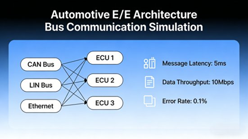
Why is bus communication simulation critical?
Bus communication simulation is critical because network behavior directly affects system timing, reliability, and function performance. As E/E systems move toward centralized and zonal layouts, communication networks must carry more data, across more protocols, with stricter timing needs.
The report notes that architectures are moving from traditional CAN toward CAN FD, automotive Ethernet, and TSN. This makes protocol compatibility, network load, and fault behavior much more important.
Bus communication simulation focuses on signal transfer, delay, interference, and bandwidth usage. It covers three main engineering tasks.
Protocol compatibility verification
Modern E/E architectures often run multiple protocols together. Engineers must verify correct signal exchange between:
- CAN
- CAN FD
- Ethernet
- TSN
- gateways between those networks
The report specifically mentions QEMU-based virtualization combined with PCI bus and Ethernet transfer channels to build more realistic virtual communication models.
Bandwidth and latency optimization
Different driving conditions create different traffic loads. Engineers simulate network behavior under:
- idle
- acceleration
- automated driving
- high sensor traffic conditions
This helps find bottlenecks and adjust priority rules or transmission cycles. The report notes that in ADAS development, where camera and LiDAR traffic are heavy, bus simulation can be used to keep key signal delay under 10 ms.
It also names RTaW-Pegase as an important tool because it supports microsecond-level timing, worst-case transmission time analysis, and bandwidth analysis.
For TSN-related timing control, IEEE 802.1Qbv is one of the relevant standards for time-aware scheduling of critical traffic.
Bus fault simulation and diagnosis
The report also covers fault injection for communication networks, including:
- short circuits
- open circuits
- signal interference
- message disturbance
One example is CAN bus interference simulation used to verify whether the diagnosis module can filter disturbed signals without false fault detection.
How does functional safety simulation support E/E architecture development?
Functional safety simulation tests whether the architecture can stay safe when faults occur. This is especially important for ADAS and automated driving systems, where safety requirements often fall in the ASIL B to ASIL D range.
ISO 26262 provides the framework for safety-related automotive E/E systems and their full lifecycle.
The report divides functional safety simulation into three main uses.
Fault injection simulation
Faults are injected into:
- ECUs
- sensors
- buses
- controllers
- system interfaces
Example faults include:
- ECU freeze
- ECU crash
- sensor drift
- bus signal loss
- corrupted communication
The report gives a practical case: in one automated driving architecture, when the main ECU failed, the backup ECU had to take over within 50 ms to support ASIL D requirements.
Safety mechanism verification
Simulation is used to verify:
- signal redundancy
- task redundancy
- hardware isolation
- dual-ECU synchronization
- failover behavior
- degraded operation
The report also references Type-1 virtualization technologies such as Xen and ACRN to test isolation between safety-critical and non-critical workloads.
Safety level evaluation
Simulation results can be used to assess whether the architecture meets its target safety level and to find hidden risks before full hardware integration.
The report specifically names Ansys medini analyze for hazard analysis, risk assessment, and support of safety design.
Why is real-time simulation central to modern E/E architecture validation?
Real-time simulation matters because centralized E/E architectures depend on strict timing across sensing, communication, compute, and actuation. If tasks are delayed or signals arrive too late, vehicle control quality and safety can be affected immediately.
The report highlights three main uses.
Task scheduling simulation
This covers the scheduling process inside ECUs or central compute platforms, including:
- task priority
- scheduling periods
- task dependency
- CPU load
- response time
The goal is to find conflicts and improve scheduling rules.
The report gives an example where a high-priority ECU task had a response time above 20 ms. After changing priority and period settings, response time was reduced to below 10 ms.
It also notes that RTaW-Pegase can analyze AUTOSAR Classic RTOS and hypervisor-based scheduling and evaluate how task activation affects network delay.
End-to-end timing analysis
This covers the full path:
sensor acquisition → bus transmission → ECU processing → actuator response
The report gives two examples:
- steering control in automated driving may require delay below 5 ms
- TSN with IEEE 802.1Qbv time-aware shaping can keep safety-critical traffic below 50 μs
Hardware adaptation through real-time simulation
The report stresses the value of connecting the virtual model to real-time hardware such as dSPACE and ETAS LABCAR for HIL testing.
This creates a closed loop between the model and real ECUs or actuators. dSPACE describes HIL as a core method for validating ECU embedded software in a realistic simulated environment, while ETAS presents DESK-LABCAR as a compact HIL system that brings testing earlier into development.
The report also explains that LABCAR benches can build a “real ECU + virtual model” closed loop, which helps verify real-time behavior and function correctness more accurately.
What is multi-domain co-simulation in automotive E/E architecture?
Multi-domain co-simulation means running E/E architecture simulation together with other engineering domains that affect vehicle behavior. This matters because the vehicle does not operate in isolated technical layers.
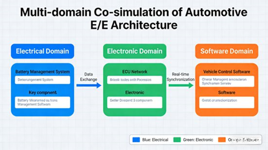
The report identifies three main combinations.
E/E architecture and vehicle dynamics co-simulation
By linking E/E models with vehicle dynamics tools such as CarSim or Siemens Simcenter Car, engineers can test how control signals affect real vehicle behavior.
The report lists examples such as:
- braking coordination
- steering response
- vehicle stability
- control algorithm tuning
It specifically mentions braking simulations used to improve braking control.
E/E architecture and ADAS algorithm co-simulation
This is used to test how:
- target detection
- path planning
- sensor transfer
- task scheduling
- actuator execution
work together across the architecture.
The report gives emergency braking in automated driving as a practical example. It also references NVIDIA DRIVE Hyperion as an architecture that supports integrated sensor, compute, and software simulation for high-level automated driving.
E/E architecture and battery system co-simulation
For electric vehicles, the E/E architecture must also coordinate with:
- battery control
- charging control
- energy management
- thermal behavior
The report says this kind of co-simulation is used to improve control accuracy, reliability, and vehicle range. It also references Infineon use of Ansys tools for battery power module thermal and control simulation.
To make cross-tool co-simulation possible, standard interfaces matter. The report specifically mentions FMI and HLA. FMI is maintained by the Modelica Association and is widely used for exchanging simulation models across tools.
What are the main engineering difficulties in automotive E/E architecture simulation?
The report identifies four main engineering difficulties:
- insufficient model fidelity
- difficulty in multi-domain co-simulation
- real-time simulation performance bottlenecks
- incomplete simulation use-case design
Each one can weaken the value of simulation if it is not handled properly.
Insufficient model fidelity
A major problem is that the virtual model may not match real vehicle behavior closely enough.
The report mentions cases where:
- ECU software logic is simplified too much
- hardware resource limits are ignored
- bus transmission behavior is not modeled realistically
- sensor error and noise are missing
It notes that some ECU models only simulate core functions and ignore runtime delay and hardware resource limits, which can lead to CPU load deviation above 10%. It also says older simulation test systems may lack controller elements and realistic communication behavior.
Difficulty in multi-domain co-simulation
This problem comes from tool mismatch. E/E architecture tools, vehicle dynamics tools, ADAS tools, and battery tools may use:
- different data formats
- different interfaces
- different time steps
- different synchronization methods
The report gives a practical example in which linking CANoe and CarSim may require custom interface development.
Real-time simulation performance bottlenecks
Modern centralized architectures include many controllers, sensors, and network nodes. That makes high-fidelity models heavy to compute, especially when they include:
- TSN timing
- multi-core scheduling
- microsecond analysis
- large communication graphs
The report says traditional simulation engines often struggle with this level of timing accuracy.
Incomplete simulation use-case design
Scenario coverage is another weak point. Automotive systems must be tested in:
- different road conditions
- different weather conditions
- normal operation
- abnormal operation
- fault conditions
- extreme automated driving scenarios
The report specifically notes missing cases for heavy rain and dense fog, which can hide sensor interference issues until later testing. It also mentions limited scenario diversity, hard-to-customize communication links, and too few functional test carriers.
How can automotive teams solve these simulation challenges?
The report proposes four groups of solutions.
Improve model fidelity
Recommended methods include:
- using a hybrid modeling method that combines physical modeling with data-driven calibration
- tuning ECU, bus, and sensor parameters using real vehicle data
- adding HIL simulation with real ECUs and sensors
- setting up model validation standards based on comparison with measured vehicle data
- keeping deviation within 5% wherever possible
The report again points to QEMU-based controller virtualization and virtual bus construction as ways to improve realism.
Solve multi-domain co-simulation difficulties
The report recommends:
- using standard interfaces such as FMI and HLA
- building a unified simulation platform
- assigning different simulation step sizes based on the timing needs of each domain
This is a practical approach because different subsystems do not need the same time resolution.
Break through real-time performance bottlenecks
The report suggests:
- multi-core CPUs
- GPU acceleration
- simplifying non-core models
- distributed simulation across multiple nodes
It says GPU acceleration can improve simulation speed by 3 to 5 times. NVIDIA also presents accelerated computing, AI, and digital twin tools as useful for automotive simulation and validation.
Improve simulation case design
The report recommends:
- building structured scenario libraries
- covering normal, abnormal, and fault conditions
- using AI to generate simulation cases automatically
- updating scenario libraries based on feedback from real vehicle testing
It gives a practical example of an automaker building a library with more than 1,000 scenarios, which raised the proportion of issues found in simulation to more than 85%.
It also notes that RTaW-Pegase topology stress testing can help find architecture limits and create more extreme scenarios.
Which simulation tools are most important for automotive E/E architecture development?
The report groups tools into three categories: general simulation tools, specialized bus simulation tools, and real-time simulation tools.
General simulation tools
MathWorks Simulink
Used for E/E architecture modeling, ECU logic, sensor models, network behavior, and connection to other domains.
Siemens Simcenter Amesim
Used for multi-domain simulation, especially when vehicle dynamics, thermal behavior, and fluid systems need to be connected.
Ansys
Used for multi-physics simulation, thermal analysis, electromagnetic analysis, and safety engineering. The report specifically mentions Ansys medini analyze.
Specialized bus simulation tools
Vector CANoe / CANalyzer
Used for CAN, CAN FD, Ethernet, and TSN simulation, signal analysis, fault injection, and bandwidth testing.
RTaW-Pegase
Used for:
- Ethernet / TSN timing analysis
- CAN FD mixed-network analysis
- multi-core scheduling analysis
- worst-case timing analysis
- TSN parameter auto-configuration
- end-to-end timing visualization
Vector VN hardware
Used to connect virtual simulation with real network hardware and increase realism.
Real-time simulation tools
dSPACE
Used for real-time simulation and HIL testing with high-fidelity models.
ETAS LABCAR
Used for ECU-focused HIL testing, fault simulation, and integrated validation.
QEMU
Used for virtual controller development, with support for multiple kernels and operating systems, reducing dependence on physical hardware during testing.
What does real engineering application look like? Two case studies
The report includes two full engineering case studies.
Case Study 1: Simulation in centralized E/E architecture development
A major automaker developing a next-generation centralized E/E architecture faced three main problems:
- topology optimization
- bus bandwidth bottlenecks
- functional safety verification
Implementation approach
- Simulink + CANoe co-simulation was used to build topology models and compare central compute + 4 zones versus central compute + 3 zones.
- RTaW-Pegase was used to simulate CAN FD and Ethernet mixed communication and adjust message priorities.
- dSPACE HIL was used for functional safety testing, including ECU faults and bus faults across 20+ fault scenarios.
Results
- harness length reduced by 22%
- architecture cost reduced by 18%
- bus utilization reduced from 75% to 55%
- critical signal delay controlled within 8 ms
- architecture verified to support ASIL D expectations
Engineering value
The report says this simulation-driven workflow reduced development time by 30%, lowered R&D cost by 25%, and reduced the number of issues first found in real vehicle testing by 80%.
Case Study 2: Multi-domain co-simulation in zonal E/E architecture for a new energy vehicle
A new energy vehicle manufacturer needed to verify how a zonal E/E architecture interacted with:
- vehicle dynamics
- battery systems
- energy management
- braking performance
Implementation approach
- A co-simulation platform was built with Simulink for E/E architecture, CarSim for vehicle dynamics, and Ansys for battery simulation.
- FMI was used for data exchange.
- The team simulated multiple driving states, including idle, acceleration, braking, and highway cruising.
- ETAS LABCAR was used for HIL testing with a real zonal controller.
Results
- energy management strategy improved
- vehicle range increased by 10%
- braking response time improved by 15%
The report also notes thermal simulation work on battery power modules using Ansys-related methods, including a 25-degree improvement in peak temperature in the source case description.
Engineering value
This case shows that E/E architecture simulation does more than improve network timing. It can also improve vehicle efficiency, thermal control, and real driving performance.
What are the future trends in automotive E/E architecture simulation?
The report identifies four future directions.
AI and simulation will be used together more often
AI can help with:
- automatic model building
- automatic scenario generation
- automatic result analysis
- closed-loop simulation and optimization
This can reduce engineering effort and improve scenario coverage.
Digital twins will be linked more closely with simulation
The next step is not just offline modeling, but real-time connection between virtual architecture models and real vehicles. That can support lifecycle monitoring and continuous system improvement.
NVIDIA presents Omniverse as a platform for industrial digital twins and simulation workflows, including automotive use.
Vehicle-cloud co-simulation will grow
As connected vehicles and V2X systems expand, simulation will increasingly include:
- V2V
- V2I
- V2P
- vehicle-cloud interaction
The report notes that RTaW-Pegase has wireless communication capability relevant to V2X protocol simulation.
Lightweight simulation will matter more
The report also points to lighter tools and lighter models for:
- field testing
- on-site diagnosis
- mobile engineering support
- flexible test workflows outside the main lab
Full engineering takeaway
Automotive E/E architecture simulation is now a core enabling technology for software-defined vehicles. It supports digital development across the whole lifecycle, from requirements and architecture design to integration testing, optimization, and later operational support.
Based on the source report, its value is clear:
- it moves validation earlier
- reduces development cost
- shortens development time
- improves reliability
- supports centralized and zonal architecture development
- helps solve topology, communication, safety, timing, and cross-domain integration problems
- supports the path toward digital twins, AI-assisted testing, and vehicle-cloud validation
The companies that build strong E/E simulation capability usually make better architecture decisions earlier and with less rework.
Frequently Asked Questions About Automotive E/E Architecture Simulation
1. Why is simulation becoming essential for modern automotive E/E architecture development?
Short answer: Because modern E/E architectures are more integrated, more software-heavy, and much harder to validate with physical testing alone.
Modern vehicles are moving from distributed ECU systems to centralized and zonal E/E architectures. That raises system complexity across computing, networking, and software coordination. Traditional validation based on physical prototypes and bench testing is expensive and slow. Simulation allows early architecture verification, large-scale scenario testing, faster software updates, and lower development cost. AWS has also described cloud-based E/E simulation and virtual ECU workflows as useful for faster V-model development.
2. What are the biggest technical challenges in E/E architecture simulation?
Short answer: The biggest challenges are model accuracy, cross-tool integration, real-time performance, and scenario coverage.
Low-fidelity ECU, sensor, or bus models can produce results that do not match real vehicle behavior. Cross-domain simulation is hard because different tools may use different interfaces and step sizes. Centralized architectures also need precise microsecond-level timing for Ethernet and TSN traffic. On top of that, building enough scenarios by hand takes a lot of time. AWS also points to similar scaling and integration issues in modern E/E simulation workflows.
3. Which simulation tools are most commonly used for automotive E/E architecture development?
Short answer: Most teams use a toolchain rather than one tool.
Common tools include MathWorks Simulink for modeling and functional simulation, Siemens Simcenter Amesim for multi-domain simulation, and Ansys, including medini analyze, for safety and multi-physics work. For communication simulation, Vector CANoe/CANalyzer and RTaW-Pegase are widely used. For real-time and HIL validation, dSPACE and ETAS LABCAR are common. Cloud-based virtual validation is also becoming more common in SDV workflows.
4. How does simulation support functional safety validation under ISO 26262?
Short answer: It lets engineers test dangerous failure cases safely before they happen in real vehicles.
Simulation supports ISO 26262-oriented validation by allowing teams to inject ECU faults, sensor failures, communication errors, and timing violations into a controlled environment. Engineers can then verify redundancy, failover timing, degraded operation, and safety mechanism behavior before road testing. ISO describes functional safety as applying to safety-related electrical, electronic, and software systems across the road vehicle lifecycle.
5. How will simulation evolve in the era of software-defined vehicles?
Short answer: It will become more cloud-based, more automated, and more closely linked to digital twins.
Simulation is moving toward digital twins, cloud-scale validation, Vehicle-in-the-Loop and HIL hybrid workflows, and AI-assisted automation. NVIDIA presents digital twins and accelerated simulation as useful for faster validation and safer deployment, while AWS describes cloud simulation as a way to scale virtual ECU and E/E architecture testing. These trends match the report’s view of AI-driven simulation, digital twin coordination, and vehicle-cloud co-simulation.
Author Bio
Johnny Liu is the CEO at Dowway Vehicle. He focuses on vehicle technology strategy, automotive systems development, and engineering-led product work. His view on automotive E/E architecture simulation comes from the need to shorten development cycles, improve system reliability, and support scalable software-defined vehicle platforms.
