

< Back to Electrical & Electronic Toolchain
By Johnny Liu, CEO at Dowway Vehicle
Published: March 19, 2026
Last Updated: March 19, 2026
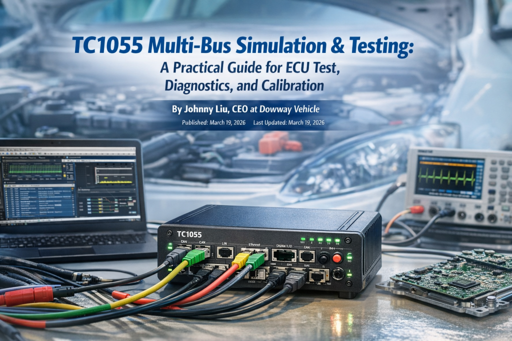
TC1055 Multi-Bus Simulation & Testing is a hardware-and-software test platform built for modern automotive network work. It brings CAN, CAN FD, LIN, Automotive Ethernet, diagnostics, flashing, calibration, logging, replay, and automation into one setup, which makes it useful from ECU development through system validation and end-of-line testing.
Modern vehicle electronics do not stay inside one bus anymore. A project may start with body control on LIN, move into CAN FD for controller communication, then hit Automotive Ethernet when ADAS, infotainment, or domain control enters the picture. That is the kind of environment this article is built around, and that is exactly where the TC1055 sits, based on your source report and public product material.
This article keeps the full technical detail from the source report. That includes protocol coverage, hardware layout, TSMaster integration, practical setup flow, three application cases, product strengths, and future direction.
- Why does a tool like TC1055 matter in current automotive testing?
- What is TC1055 Multi-Bus Simulation & Testing?
- What protocols and hardware interfaces does TC1055 include?
- How does TC1055 fit modern multi-bus vehicle architecture?
- What are the main technical features of TC1055?
- What functions does TC1055 cover across the test and calibration process?
- How does TC1055 handle expansion and custom setups?
- What does the hardware architecture look like in practice?
- How does TC1055 work with TSMaster software?
- What is the practical workflow for an ECU communication test with TC1055?
- Where is TC1055 used in real automotive projects?
- What makes TC1055 stronger than many conventional single-bus tools?
- What is the future direction for TC1055 and similar tools?
- FAQs
- 1) What protocols and bus types does a multi-bus automotive test tool like TC1055 support?
- 2) How do I choose the correct bit rate and protocol configuration for CAN/CAN FD when setting up a test?
- 3) Can multi-bus tools integrate with common ECU calibration or analysis software?
- 4) What are the use cases engineers ask about most often with these tools?
- 5) How do I set up high-speed Ethernet testing in automotive environments?
- Final word
- Author Bio
Why does a tool like TC1055 matter in current automotive testing?
A short answer: it helps engineers test more of the vehicle network with fewer separate devices.
The source report makes the point clearly. Automotive testing and calibration now run through the whole product cycle, from low-level ECU debugging and communication checks to full-vehicle integration, production inspection, and parameter tuning. A tool that only handles one protocol or one step in the process creates extra setup work and slows the team down.
Public TOSUN material places TC1055 in that broader workflow too. The official product pages describe it as a multi-bus simulation and test tool for CAN, LIN, and Automotive Ethernet, used with TSMaster for analysis, simulation, diagnostics, calibration, flashing, automation, and end-of-line tasks.
What is TC1055 Multi-Bus Simulation & Testing?
A short answer: it is a multi-bus automotive simulation, test, diagnostics, and calibration platform.
TC1055 Pro is presented by TOSUN as a multi-channel tool for CAN / CAN FD, LIN, and Automotive Ethernet. The public product pages and datasheets say it works with TSMaster software and supports message analysis, simulation, diagnostics, ECU flashing, CCP/XCP calibration, DoIP, SOME/IP, data logging, replay, and automation.
In the source report you provided, TC1055 is framed as a full-process tool for passenger cars, commercial vehicles, and new-energy vehicles. The report also places it in engine control, body control, chassis control, and driver assistance testing, not just in a narrow lab-only setup.
What protocols and hardware interfaces does TC1055 include?
A short answer: TC1055 combines CAN / CAN FD, LIN, Automotive Ethernet, and I/O on one device.
Public product information confirms the following interface set for TC1055 Pro:
- 4 CAN channels with Classical CAN bit rates from 125 kbps to 1 Mbps
- CAN FD support up to 5 Mbps
- 2 LIN channels with software-configurable master/slave mode and 0–20 kbps
- 4×100/1000Base-T1 Automotive Ethernet channels
- 2×100Base-Tx / 1000Base-T standard Ethernet channels with software switching
- Bypass mode for Automotive Ethernet continuity-sensitive scenarios
- 4 DIDO channels
- 3 AIAO channels
- Software-configurable built-in 120 Ω termination on CAN
- 1 μs hardware timestamps
- Gigabit Ethernet, 10G Ethernet, and USB3.0 PC-side connectivity
That matches the core hardware picture in your report. The report also states that TC1055 Pro+ extends the idea into CAN XL, with 4 CAN XL channels, aimed at next-generation high-speed in-vehicle networks. A recent TOSUN CAN XL solution page also lists TC1055 Pro+ with 4 CAN XL, 4 Automotive Ethernet, 2 LIN, digital I/O, analog I/O, and high-precision multi-device time sync.
How does TC1055 fit modern multi-bus vehicle architecture?
A short answer: it lets engineers work across old and new vehicle networks without stitching several test boxes together.
Your report stresses the shift from single-bus architectures to mixed networks with higher bandwidth and tighter timing demands. TC1055 is built for that mixed environment. It can stay on familiar CAN and LIN work, but it also reaches into Automotive Ethernet and future CAN XL development.
That matters because real projects now cross domain boundaries. A body controller may still use LIN. A VCU or powertrain controller may live on CAN FD. A gateway, ADAS function, or infotainment path may push traffic over Automotive Ethernet. In your report, that is one of the main reasons TC1055 is presented as “one device for multiple jobs.”
What are the main technical features of TC1055?
A short answer: the platform is built around multi-bus coverage, fast data handling, timing precision, and end-to-end test support.
Multi-bus protocol support
TC1055 supports CAN, CAN FD, LIN, and Automotive Ethernet in one platform. The source report also adds J1939 to the simulation side, which matters in commercial-vehicle and heavy-duty work. Public TSMaster material confirms multi-bus simulation, including CAN, LIN, and J1939-related workflows through the software environment.
The report also points out that this cuts down system complexity because the engineer does not have to add extra modules for each bus type just to build one bench.
High-speed data transport and real-time handling
TC1055 uses Gigabit Ethernet, 10G Ethernet, and USB3.0 to connect to the PC. The public product page says this is done to avoid PC-side communication bottlenecks during large amounts of bus data processing.
That lines up with the source report’s point about real-time data capture, high-bandwidth traffic, ECU calibration, bus-load testing, and fault simulation. When Ethernet traffic and several ECUs are active at once, slow PC links become a problem fast.
Microsecond timestamping and multi-device time sync
TC1055 provides μs-level hardware timestamps and supports multi-device hardware time synchronization. Those features are listed on the public product page and datasheet.
In the source report, those timing features are tied to fault tracing, delay checks, and system-level validation where multiple ECUs act together. That is the kind of detail engineers care about when debugging message timing, gateway delay, or multi-node interactions.
Automotive-grade hardware design
Public TOSUN material describes TC1055 as an automotive-grade design, with Windows and Linux driver-free support, hardware caching, and wide DC power input. The product page lists 9–28 V DC supply range and environmental operating conditions from -40°C to 80°C.
Your source report adds the field side of that: good EMI resistance, vibration resistance, and use in both lab testing and real-vehicle road tests.
What functions does TC1055 cover across the test and calibration process?
A short answer: simulation, acquisition, analysis, diagnostics, flashing, calibration, and automation all sit inside the same workflow.
The source report divides the workflow into four practical blocks, and it makes sense to keep that structure.
Bus simulation
TC1055 supports simulation of CAN, LIN, Automotive Ethernet, and J1939-related work through TSMaster-based workflows. The report also says it can simulate ECU nodes, build rest-bus simulation, and inject faults such as:
- message loss
- error frames
- high bus load
TSMaster public material confirms multi-bus simulation, graphical panels, soft-HIL style ECU code simulation, C/Python mini-program support, and test-panel customization.
The source report also mentions TSMaster’s built-in Panel function, which can link bus signals to graphical displays for a more direct view of simulation status.
Data capture and analysis
The report says TC1055 supports BLF and ASC recording and replay, long-duration and high-bandwidth acquisition, real-time timestamps, and trigger storage. Public product material confirms BLF/ASC logging and online/offline replay.
The report adds the analysis layer:
- DBC, LDF, XML, and ARXML database loading
- message parsing
- signal monitoring
- bus-load statistics
- peak load rate
- data frame rate
- error frame count
- graphical and numeric display
Public TSMaster and TC1055 materials confirm database loading and monitoring/analysis functions with trace, numeric, and chart-style displays.
Diagnostics and calibration
The report says TC1055 supports:
- UDS diagnostics
- ECU flashing over UDS or DoIP
- CCP/XCP calibration
- SeedKey editing
- diagnostic parameter configuration
- basic diagnostic service editing
- custom automated diagnostic flows
Public TOSUN material confirms UDS diagnostics, ECU flashing, CCP/XCP, DoIP, and TSMaster-based automation. Separate TSMaster support pages also confirm two SeedKey handling methods: loading an external DLL or adding the security algorithm directly in the TSMaster compiler.
That SeedKey point matters more than it looks. It means engineers do not always need to jump into external tooling just to handle security access logic.
Automated testing
The report says TC1055 supports both ECU-level and system-level automated testing. It also states that engineers can write their own test scripts so procedures run automatically, data is recorded automatically, and reports are generated with less manual work.
Public TSMaster pages back up that software side. TSMaster supports C scripts, Python scripts, custom test logic, custom simulation panels, and automatic report generation.
How does TC1055 handle expansion and custom setups?
A short answer: the tool is built to grow with the bench.
The source report says TC1055 supports:
- multi-device cascading for more channels
- linking with TLog1057 for a simulation-record-analysis workflow
- custom message formats
- custom test scripts
- integration with third-party tools such as LabVIEW and MATLAB/Simulink
Public TOSUN material confirms Matlab/Simulink co-simulation, downloadable API documentation, example code, and API resources that include Python and LabVIEW cases. A recent TOSUN CAN XL solution page also mentions TLog1057 for long-duration high-bandwidth logging and a linked simulation-record-analysis workflow.
That is useful when a lab outgrows a simple single-device setup and needs a bigger bench, more channels, or tighter links into custom software.
What does the hardware architecture look like in practice?
A short answer: the hardware is modular, compact, and meant for both bench work and vehicle use.
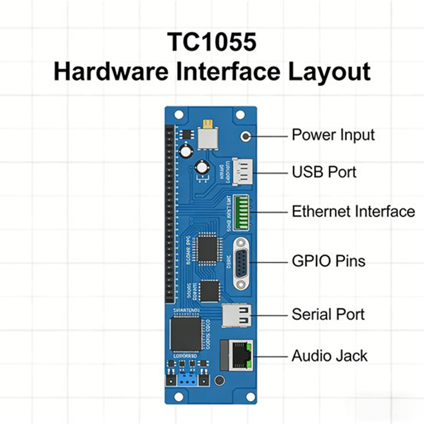
The source report breaks the device into five practical hardware parts.
1. Core control module
This is the main processing unit. It handles protocol parsing, timing, synchronization, and command execution so several buses can run together without falling apart. In the report, this is described as the part that lets CAN, LIN, and Automotive Ethernet run in parallel during complex tests.
2. Bus interface module
This is where the ECU and network connections happen. The report notes that the interfaces use standardized design, so engineers can connect directly to ECUs and network nodes without extra conversion hardware. It also repeats the point that the CAN channels have software-configurable termination, which helps adapt to different bus topologies and reduce reflection issues during setup. Public product information confirms built-in 120 Ω CAN termination and the main bus-channel counts.
3. I/O interface module
The source report gives this section proper weight, and it should stay that way. TC1055 includes 4 DIDO and 3 AIAO, which means it can connect to external sensors and actuators, not just bus lines. The report frames this as useful for HIL-style setups and ECU input/output response checks. Public product pages confirm both DIDO and AIAO are part of the hardware.
4. Communication interface module
The report says engineers can pick Gigabit Ethernet, 10G Ethernet, or USB3.0 depending on the setup. Lab benches may use Ethernet for faster data transport and easier multi-device work. In-vehicle tests may lean on USB3.0 for simpler hookup. Public product pages confirm all three PC-side links.
5. Power and status indicator module
The report says TC1055 supports wide-voltage input for 12 V and 24 V vehicle power systems, along with status LEDs that show operating state, bus status, and data activity. Public product information lists 9–28 V DC power input, which fits that vehicle-use range.
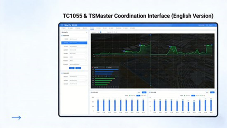
How does TC1055 work with TSMaster software?
A short answer: TSMaster is the main software layer that turns TC1055 into a full test and calibration platform.
Public TSMaster material says the software can connect to and control TOSUN hardware for monitoring, simulation, diagnostics, calibration, bootloader work, I/O control, testing, measurement, and EOL tasks. It also supports embedded-code generation, C and Python scripting, custom mini-program logic, report generation, and Matlab/Simulink co-simulation.
The source report adds the day-to-day engineering view.
Database compatibility
TSMaster supports DBC, LDF, XML, and ARXML loading. Public TC1055 pages confirm those formats.
The report says that lets engineers import whole-vehicle or ECU databases directly, map messages and signals fast, and avoid hand-building every frame layout.
Graphical interface and live monitoring
The report describes a graphical interface where engineers can watch bus load, message traffic, and signal values in real time, with support for multiple windows and multiple bus channels at once. It also mentions waveform-style views and instrument-style displays for signal trends.
Public TSMaster pages confirm trace display, numeric display, chart display, bus statistics, message monitoring, replay, and message sending.
Script editing and automation
The report says TSMaster includes a built-in editor for Python and C, letting engineers build automated procedures such as fault injection, data capture, and report output. Public TSMaster pages confirm C script support, Python script support, and report generation.
Data export and analysis
The source report says captured data can be exported to Excel, BLF, and ASC. It also says the software includes analysis for bus load, message delay, and fault statistics.
Public TC1055 material confirms BLF and ASC recording and replay, while TSMaster pages confirm the broader analysis workflow.
What is the practical workflow for an ECU communication test with TC1055?
A short answer: connect, configure, simulate, capture, analyze, then calibrate if needed.
The source report lays out a five-step engineering workflow, and it is worth keeping almost as-is because it reads like a real test bench sequence.
Step 1: Connect the hardware
Connect TC1055 to the PC through USB3.0 or Ethernet. Make sure power is stable. Connect the CAN, LIN, or Ethernet ports to the target ECU or vehicle network. Set the terminal resistance for the bus if needed. Add external sensors or actuators if the test uses I/O interaction.
Step 2: Configure the software
Open TSMaster and connect to TC1055. The source report states that the software can recognize the device directly under the driver-free setup. Import the ECU or vehicle database, such as a DBC file. Set bus parameters such as protocol type and bit rate so they match the target ECU network.
Step 3: Run simulation and testing
Start bus simulation. Send messages manually, run cyclic messages, or inject faults such as message loss and error frames. Watch bus load, message flow, and signal values live. Use the diagnostic functions to run UDS services and check ECU diagnostic response.
Step 4: Capture and analyze data
Stop the test. Export the recorded data. Use the analysis tools to check bus-load changes, message delay, error-frame count, and communication stability. Create a test report from the result.
Step 5: Calibrate parameters if needed
If the job includes calibration, use CCP/XCP in TSMaster to connect to the ECU calibration interface, read current values, change parameters, write them back, and then verify behavior after the calibration change.
Where is TC1055 used in real automotive projects?
A short answer: the report places it in new-energy vehicle control testing, end-of-line ECU work, and Automotive Ethernet gateway validation.
Case 1: New-energy vehicle VCU communication test
The source report describes a new-energy vehicle project where engineers had to verify communication between the VCU, MCU, BMS, and OBC. The setup involved CAN FD and Automotive Ethernet. TC1055 handled the CAN FD channels for VCU, MCU, and BMS, and the Ethernet channels for OBC and VCU. TSMaster loaded the vehicle database using DBC + ARXML, then the team ran multi-ECU simulation, rest-bus simulation, fault injection for overload and message loss, and live data capture.
The report says this let the team test VCU communication compatibility without building a full vehicle environment. It also points to the μs-level timestamps as a useful aid in pinning down when a communication fault happened and what the network looked like at that moment.
Case 2: ECU end-of-line calibration and inspection
The source report’s second case is production work. A supplier needed engine ECU line-end checks that covered communication, UDS diagnostics, parameter calibration, and flashing, with a target cycle time of 5 minutes or less per ECU.
The report says each station used one TC1055 connected through USB3.0, and automated scripts handled the full sequence. Test data was captured automatically, reports were generated automatically, and failed ECUs were flagged automatically. The reported result was a drop to about 3 minutes per ECU, which met the production takt target.
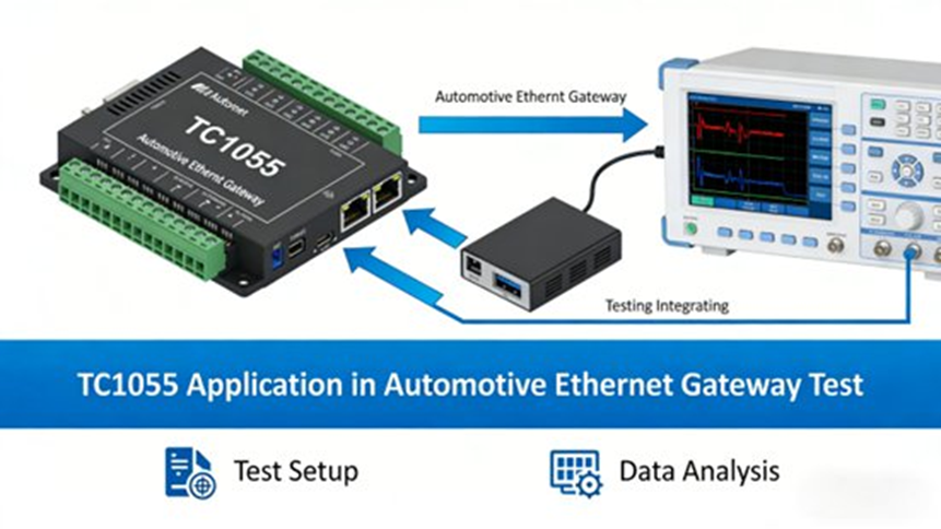
Case 3: Automotive Ethernet gateway test
The third case in the source report is a gateway test for a smart-driving vehicle project. Engineers needed to check forwarding delay, forwarding accuracy, and fault tolerance between CAN FD and Automotive Ethernet. TC1055 sent traffic into the CAN FD side, observed the forwarded frames on the Ethernet side, measured forwarding delay, and injected message errors and network interruptions.
The report says the setup could measure forwarding delay with error no greater than 10 μs, while also checking recovery behavior during abnormal network conditions.
What makes TC1055 stronger than many conventional single-bus tools?
A short answer: it covers more protocols, gives tighter timing, reduces setup sprawl, and cuts repeated manual work.
The source report breaks this into four product strengths.
1. Multi-bus coverage
Instead of using one tool for CAN, another for LIN, and another for Ethernet, TC1055 pulls them into one device. That helps when a project spans body electronics, powertrain, gateway testing, and Ethernet-heavy systems.
2. Performance
The report points to fast PC links, μs-level time sync, and automotive-grade design as reasons the device handles heavier traffic and tougher environments better than many older or narrower tools. Public product pages confirm high-speed PC connectivity, 1 μs timestamps, hardware caching, and automotive-grade design.
3. Ease of use
The report highlights Windows and Linux driver-free support, TSMaster’s graphical interface, automation scripting, modular design, and field portability. Public product and software pages confirm driver-free Windows/Linux support and C/Python automation.
4. Cost control
The source report makes a practical point here: one tool that covers several buses can replace several narrower devices. Add automation and lower manual effort on top, and the savings go beyond hardware purchase alone.
What is the future direction for TC1055 and similar tools?
A short answer: more mixed networks, more bandwidth, more Ethernet, and more demand for tools that can keep up.
The source report says vehicle networks are moving toward mixed-bus, high-bandwidth, high-timing-precision setups. It also says ECU functions will keep getting denser, which raises the bar for protocol coverage, timing, and expansion. That matches recent TOSUN material around CAN XL development, where TC1055 Pro+ is presented for next-generation network simulation and testing with multi-node sync, HIL-style I/O, and broader system coverage.
The report’s closing outlook says TC1055 is expected to keep growing in three directions:
- stronger multi-bus joint testing
- more automation
- wider support for smart driving and connected-vehicle scenarios
That is a fair reading of where this kind of tool is heading.
FAQs
1) What protocols and bus types does a multi-bus automotive test tool like TC1055 support?
Short answer: It supports CAN, CAN FD, LIN, and Automotive Ethernet on one platform.
Public TC1055 product material confirms 4 CAN / CAN FD, 2 LIN, 4×100/1000Base-T1, and 2×100Base-Tx / 1000Base-T channels, with software mode switching for the Ethernet side. Your source report also adds CAN XL support on the TC1055 Pro+ path.
2) How do I choose the correct bit rate and protocol configuration for CAN/CAN FD when setting up a test?
Short answer: Match the tool settings to the ECU network and make sure termination is correct.
Public product pages say TC1055 supports 125 kbps to 1 Mbps for Classical CAN and up to 5 Mbps for CAN FD, while the CAN channels also have software-configurable 120 Ω termination. In real bench work, wrong bit rate or wrong termination is one of the fastest ways to get unstable communication.
3) Can multi-bus tools integrate with common ECU calibration or analysis software?
Short answer: Yes. TC1055 is built to work with TSMaster, and that covers analysis, diagnostics, flashing, and calibration.
Public TOSUN material says TSMaster supports DBC, LDF, XML, and ARXML loading along with message monitoring, simulation, UDS diagnostics, ECU flashing, DoIP, and CCP/XCP calibration. The source report also notes custom automation and reporting inside the same workflow.
4) What are the use cases engineers ask about most often with these tools?
Short answer: Rest-bus simulation, fault injection, automation, diagnostics, calibration, and gateway testing.
Your source report centers on exactly those jobs: simulating missing ECUs, injecting dropped frames and bus errors, running automated test scripts, using CCP/XCP for calibration, and checking communication behavior across CAN FD and Automotive Ethernet. Public TSMaster pages support the broader simulation, automation, diagnostics, and calibration side of that workflow.
5) How do I set up high-speed Ethernet testing in automotive environments?
Short answer: Use the right physical interface, set the mode in software, and keep the network path consistent during the test.
Public TC1055 material says the tool provides 4×100/1000Base-T1, 2×100Base-Tx / 1000Base-T, software switching, and bypass mode. The source report ties those features to Ethernet communication testing, gateway work, and cases where network continuity has to stay intact during test execution.
Final word
TC1055 is not just a CAN box with a few extra ports. Based on your source report and the public TOSUN material, it is a full automotive test-and-calibration platform that covers multi-bus simulation, data capture, replay, diagnostics, flashing, calibration, automation, I/O interaction, and expansion into more complex benches.
It fits bench debugging.
It fits system integration.
It fits production inspection.
It also fits the current shift toward mixed-bus vehicle networks where CAN, LIN, and Automotive Ethernet have to be tested together.
That is why it makes sense as a cluster-page topic and why the article is strongest when it keeps the full engineering detail intact.
Author Bio
Johnny Liu is the CEO at Dowway Vehicle. He focuses on vehicle technology, automotive electronics, and engineering-led product communication. This article is based on the TC1055 source report you provided and checked against public TOSUN and TSMaster product materials.
