


< Back to Automotive Design Toolchain
Automotive CAD workflow is the process engineers use to design, adjust, and prepare vehicle components for production. It connects 2D drawings, 3D models, simulation, and manufacturing into one continuous system. In practice, CAD sits right in the middle of everything.
- Why This Workflow Matters in Real Projects
- Key Stages in Automotive Design
- Why Efficiency Matters
- CAD as the Central Data Source
- Integration with CAE, CAM, and PLM
- Parametric Modeling and Constraints
- 2D Engineering Drawing Standards
- Parts Libraries and BOM Management
- Batch Processing
- From Sketch to Model
- Lightweight 3D Modeling
- Keeping 2D and 3D in Sync
- Crankshaft Design
- Wheel Design
- Shaft Design
- Assembly Workflow
- Motion Simulation
- Interference Detection
- Drawing Generation
- Annotation
- Export
- Multi-User Work
- Version Comparison
- Cross-Platform Support
- CAE
- CAM
- PLM
- Compatibility
- Performance
- Cost
- Data Control
- Weifu Group
- Wanda Bus
- AI Design
- Lightweight Engineering
- Integration
- Is GstarCAD fully compatible with AutoCAD workflows?
- How does GstarCAD handle large automotive assemblies?
- Does GstarCAD support parametric design?
- What common issues do users face?
- How does GstarCAD support team collaboration?
- CAD is the core system in automotive engineering
- Workflow runs from 2D → 3D → simulation → manufacturing → lifecycle
- Parametric design saves time during iteration
- Integration with CAE, CAM, PLM keeps data consistent
- Gstarsoft CAD supports compatibility, performance, and team workflows
Why This Workflow Matters in Real Projects
Here’s something that happens more often than people admit.
A model gets updated.
But the simulation team runs the old file.
Or manufacturing gets a drawing that’s one version behind.
That’s not a software problem.
It’s a workflow gap.
And most of those gaps start inside CAD.
What Is an Automotive CAD Software Workflow?
Short Answer:
An automotive CAD workflow is the step-by-step process of creating, updating, and managing design data using CAD software, while keeping everything connected to simulation and manufacturing systems.
Key Stages in Automotive Design
- Concept layout
- 2D drafting
- 3D modeling
- CAE simulation
- CAM preparation
- PLM management
Why Efficiency Matters
A single vehicle program can involve thousands of parts.
Small delays in one step can ripple across the entire project.
Where CAD Fits in the Automotive Toolchain
Short Answer:
CAD is the system where all design data begins. It creates the geometry and structure that simulation, manufacturing, and lifecycle systems depend on.
CAD as the Central Data Source
CAD defines:
- Geometry
- Dimensions
- Relationships between parts
Everything else builds on this.
Integration with CAE, CAM, and PLM
Gstarsoft CAD supports:
- DWG / DXF
- STEP / IGES
This allows:
- Direct simulation without rebuilding models
- Smooth transition into manufacturing
Core Capabilities Required in Automotive CAD Software
Short Answer:
A capable automotive CAD system needs parametric modeling, standard-compliant drawings, part libraries, batch tools, and stable performance with large files.
Parametric Modeling and Constraints
Let’s keep it simple.
You change one dimension.
Everything else updates.
That’s how engineers handle iterations without starting over.
2D Engineering Drawing Standards
Supports:
- ISO, DIN, ANSI
- GD&T
- Surface roughness
Without these, production teams can’t use the design.
Parts Libraries and BOM Management
Includes:
- Standard components
- Assembly structure tracking
Batch Processing
In real projects:
- Hundreds of drawings
- Multiple revisions
Batch tools handle:
- Printing
- Splitting
- File management
2D and 3D Design Workflow
Short Answer:
Automotive CAD combines 2D and 3D work so engineers can design clearly and still meet production requirements.
From Sketch to Model
- Draw sketch
- Add constraints
- Build features (extrude, cut, fillet)
Lightweight 3D Modeling
Gstarsoft CAD focuses on:
- Practical mechanical modeling
Used for:
- Wheels
- Shafts
- Structural parts
Keeping 2D and 3D in Sync
When the 3D model changes:
👉 The 2D drawing updates automatically
Automotive Component Design Workflow
Short Answer:
Component design uses parametric sketches, 3D modeling, and tolerance definition to create parts that are ready for assembly and production.
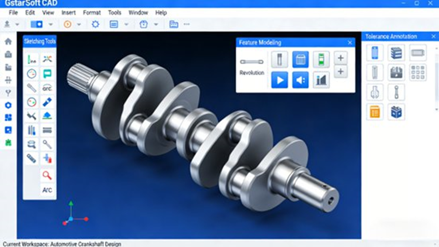
Crankshaft Design
Steps:
- Sketch layout
- Apply constraints
- Build 3D model
- Add tolerances
Wheel Design
- Balance strength and appearance
- Adjust dimensions for different models
Shaft Design
Includes:
- Threads
- Keyways
- Standard forms
Assembly Design and Interference Checking
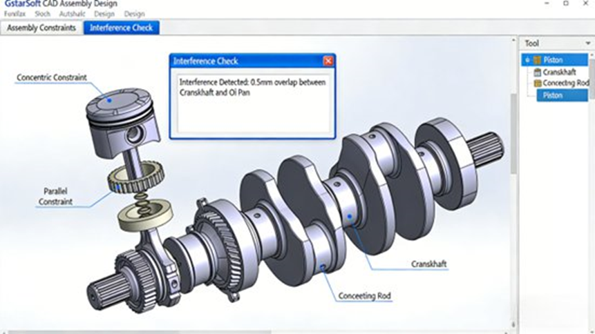
Short Answer:
Assembly design ensures parts fit together correctly and move as expected, using constraints and interference checks.
Assembly Workflow
- Import parts
- Apply constraints
- Define movement
Motion Simulation
Used to test:
- Rotation
- Link movement
Interference Detection
If parts collide, the system highlights it.
Fixing this early avoids manufacturing problems.
Engineering Drawing Output
Short Answer:
Engineering drawings convert 3D models into clear 2D instructions for manufacturing.
Drawing Generation
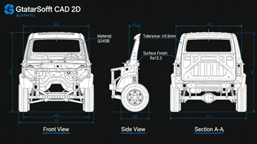
Includes:
- Multi-view
- Section view
- Detail view
Annotation
- Dimensions
- Tolerances
- Surface finish
Export
Supports:
- JPG
Collaboration and Workflow Management
Short Answer:
Modern CAD systems allow teams to work together, track changes, and manage versions across departments.
Multi-User Work
Teams can:
- Edit files
- Share updates
Version Comparison
DWG Compare shows:
- What changed
- Where changes happened
Cross-Platform Support
Runs on:
- Windows
- Linux
- macOS
Integration with CAE, CAM, and PLM
Short Answer:
CAD connects directly to simulation, manufacturing, and lifecycle systems, forming a complete engineering workflow.
CAE
- Stress analysis
- Fatigue testing
CAM
- Toolpath generation
- CNC preparation
PLM
- Version tracking
- Data control
Advantages of Gstarsoft CAD
Short Answer:
Gstarsoft CAD provides compatibility, stable performance, lower cost, and better control over design data.
Compatibility
- Works with DWG
- Similar workflow to AutoCAD
Performance
- Handles large drawings
- Faster operations
Cost
- Lower licensing cost
Data Control
- Local storage
- Controlled access
Real-World Applications
Short Answer:
Companies use Gstarsoft CAD to improve design consistency, reduce errors, and manage large volumes of engineering drawings.
Weifu Group
- Improved drawing management
- Better standardization
Wanda Bus
- Reduced design errors
- Faster workflow
Future Trends
Short Answer:
Automotive CAD is moving toward smarter automation, lighter designs, and tighter system integration.
AI Design
- Smarter modeling
- Faster iteration
Lightweight Engineering
- Less material
- Better performance
Integration
- Fully connected systems
🔍 FAQs (Optimized for Search & AI)
Is GstarCAD fully compatible with AutoCAD workflows?
Short Answer:
Yes, Gstarsoft CAD works with DWG/DXF, AutoLISP, and similar commands, allowing engineers to use existing AutoCAD files without conversion.
Full Answer:
It supports command logic, fonts, and menu systems, making it easy to switch without breaking existing workflows or data connections.
How does GstarCAD handle large automotive assemblies?
Short Answer:
It handles large drawings efficiently with faster load times and optimized commands.
Full Answer:
The 2026 version improves performance in TRIM, EXTEND, and Xref operations, which helps when working with engines, chassis, and multi-part assemblies.
Does GstarCAD support parametric design?
Short Answer:
Yes, it includes constraints and parameter tools for controlled design changes.
Full Answer:
Engineers can adjust dimensions and update dependent geometry automatically, which is useful for parts like shafts and crankshafts.
What common issues do users face?
Short Answer:
Issues usually involve plotting, performance, or command interruptions.
Full Answer:
These can be solved by cleaning files, reducing open drawings, and checking plot settings. The issues are similar to other CAD tools.
How does GstarCAD support team collaboration?
Short Answer:
It supports version comparison, file referencing, and shared workflows.
Full Answer:
Features like DWG Compare and Xrefs help teams manage changes across departments and keep projects organized.
👤 Author
Johnny Liu
CEO at Dowway Vehicle
15+ years in automotive engineering, focusing on CAD workflows, system integration, and vehicle development.
Last Updated: March 23, 2026
