

< Back to Intelligent Chassis Software
Last Updated: March 24, 2026
Author: Johnny Liu, CEO at Dowway Vehicle
- Direct Answer
- Why This Matters
- Role in By-Wire Chassis Systems
- 6 Degrees of Freedom
- Real Scenario
- Why VMC Is Needed
- Short Answer
- Hardware Abstraction Layer (HAL)
- Basic Software Layer (BSW)
- Application Layer (APP)
- Short Answer
- State Estimation (EKF)
- Trajectory Tracking (MPC)
- Control Allocation (Core)
- Execution Control
- Short Answer
- Longitudinal Control
- Lateral Control
- Vertical Control
- State Estimation
- Short Answer
- Short Answer
- Key Constraints
- Real Issues
- Short Answer
- Results
- Drift Mode
- Short Answer
- Short Answer
- Key Measures
- Safety Mechanisms
- Short Answer
- Short Answer
- Short Answer
- What is the core role of a VMC?
- How does VMC enable multi-actuator coordination?
- What are the biggest challenges in VMC development?
- What models are used in VMC?
- How is VMC evolving?
- Is VMC replacing ESC or EPS?
Direct Answer
A Vehicle Motion Controller (VMC) is the central software system that controls steering, braking, suspension, and drive systems together. It takes driver or autonomous inputs, estimates vehicle state, and distributes commands across actuators in real time to keep the vehicle stable, safe, and predictable.
- VMC is the control center of a by-wire chassis
- Replaces separate ECUs with one coordinated system
- Core modules: estimation, tracking, allocation, execution
- Runs on real-time AUTOSAR architecture
- Designed to meet ASIL-D safety
Why This Matters
Let me put it simply.
Most control problems don’t come from bad algorithms.
They come from systems not agreeing with each other.
I’ve seen cars behave perfectly in simulation, then feel unstable on real roads. The issue wasn’t math. It was coordination. That’s exactly what VMC fixes.
What Is a Vehicle Motion Controller (VMC)?
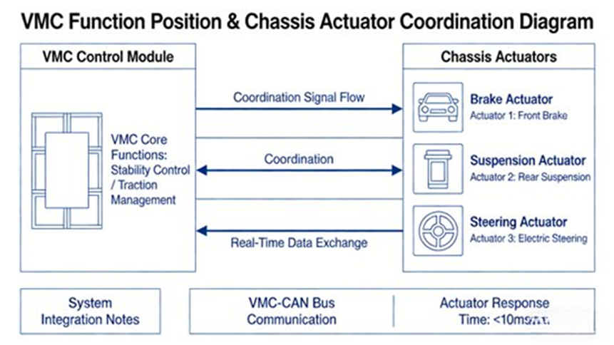
A VMC is a centralized control system that manages how a vehicle moves in real time. It connects all chassis actuators and ensures they work together instead of independently.
In practice:
- Input: steering, acceleration, braking, trajectory
- Output: torque, brake pressure, steering angle, suspension behavior
Role in By-Wire Chassis Systems
VMC directly controls:
- Steer-by-Wire (SBW)
- Brake-by-Wire (EMB / One-Box)
- Active Suspension (CDC / MR dampers)
- Electric drive systems
6 Degrees of Freedom
- Longitudinal motion
- Lateral motion
- Vertical motion
- Pitch
- Roll
- Yaw
This is not just control anymore. It’s full vehicle dynamics management.
Why Traditional Chassis Control Is No Longer Enough
Older systems like ESP and EPS operate on their own.
That worked before. It doesn’t now.
Real Scenario
During a quick lane change:
- Steering tries to follow the path
- Braking tries to stabilize
- Suspension reacts late
Each system is doing its job.
Together, they don’t produce the best result.
Why VMC Is Needed
- One controller instead of many
- Real-time coordination
- Required for advanced driver assistance and beyond
VMC Software Architecture
Short Answer
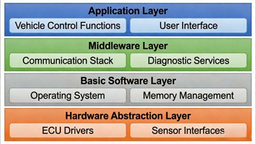
VMC uses a layered architecture with hardware abstraction, basic software, and application layers to ensure real-time performance and reliability.
Hardware Abstraction Layer (HAL)
This layer hides hardware details.
- CAN FD / FlexRay communication
- Sensor interfaces (IMU, wheel speed)
- Actuator interfaces
It allows the same software to run on different hardware platforms.
Basic Software Layer (BSW)
This layer handles execution and safety.
- RTOS (≤10 ms cycle)
- Diagnostics
- Fault management
- Communication
It follows AUTOSAR Classic Platform.
Application Layer (APP)
This is where control logic runs.
- State estimation
- Trajectory tracking
- Control allocation
- Execution control
- Feature functions
Core Functional Modules
Short Answer
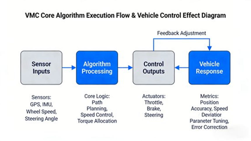
VMC relies on four core modules: state estimation, trajectory tracking, control allocation, and execution control.
State Estimation (EKF)
Not all states can be measured.
So we estimate them.
- Slip angle
- Yaw rate
- Road friction
Uses Extended Kalman Filter with sensor fusion.
Accuracy matters. Even small errors affect control quality.
Trajectory Tracking (MPC)
This module compares desired path with actual motion.
- Prediction horizon: 0.5–1 s
- Control horizon: 0.1–0.2 s
At high speed → focus on stability
At low speed → focus on accuracy
Control Allocation (Core)
This is where everything comes together.
It distributes control across:
- Wheels
- Brakes
- Steering
- Suspension
Uses optimization (QP solver).
If one actuator fails, the system adjusts instantly.
Execution Control
Turns commands into real actions.
- SBW → position control
- EMB → pressure control
Response must stay within 10 ms.
Control Algorithms in VMC
Short Answer
Production VMC systems use a mix of proven control methods rather than relying on a single advanced algorithm.
Longitudinal Control
- PID + feedforward
- Smooth acceleration and braking
- One-Pedal control blending
Lateral Control
- MPC + PID
- Balances accuracy and stability
- Supports torque vectoring
Vertical Control
- Fuzzy + PID
- Controls pitch and roll
State Estimation
- EKF for nonlinear dynamics
Vehicle Dynamics Models
Short Answer
Different models are used depending on speed and accuracy needs.
| Model | Usage |
| 2–4 DOF | Real-time control |
| 7 DOF | Integrated dynamics |
| 15 DOF | Simulation / HiL |
In real projects, you don’t rely on one model. You mix them.
Engineering Challenges
Short Answer
The hardest part is not building the algorithm—it’s making it work under real constraints.
Key Constraints
- MCU compute: 200–500 DMIPS
- Control cycle: ≤10 ms
- Temperature: -40°C to 85°C
Real Issues
- Coupled systems
- Limited compute
- Complex calibration
- Changing road conditions
Most teams underestimate calibration effort.
Real-World Case
Short Answer
A production SUV program shows how VMC improves performance across multiple scenarios.
Results
- One-Pedal jerk ≤0.3g
- Speed error ≤0.5 km/h
- Lateral deviation ≤5 cm @120 km/h
- Cornering limit improved by 15%
Drift Mode
- Controlled rear torque
- Adjustable angle (0–30°)
Development Process
Short Answer
VMC development follows a structured lifecycle aligned with ISO 26262.
- Requirements (SRS)
- Architecture (ADS)
- Development (MISRA C)
- Integration (HiL)
- Vehicle testing
- Production + OTA
Functional Safety (ASIL-D)
Short Answer
VMC must meet ASIL-D, the highest safety level in automotive systems.
Key Measures
- FMEA and FTA
- Hardware redundancy
- Software redundancy
- Fault detection and fallback
Safety Mechanisms
- Memory protection
- Task isolation
No single failure should lead to loss of control.
Validation Methods
Short Answer
Validation combines simulation, hardware testing, and real vehicle testing.
- Unit testing
- HiL testing
- Real-world testing
- Third-party certification
Key Technical Challenges Today
Short Answer
Modern VMC systems must balance performance, safety, and cost under tight constraints.
- Multi-actuator coordination
- Compute limitations
- Scenario coverage
- Cost vs safety
Future Direction of VMC
Short Answer
VMC is becoming a core system in software-defined vehicles, tightly connected with ADAS and cloud systems.
- Adaptive control using AI
- Cross-domain integration
- Digital twin testing
- Cloud-based optimization
People Also Ask (Trending FAQs)
What is the core role of a VMC?
A VMC coordinates steering, braking, suspension, and propulsion to control vehicle motion.
It replaces isolated ECUs with a unified system.
This improves stability, response, and consistency across driving scenarios.
How does VMC enable multi-actuator coordination?
VMC converts global motion targets into actuator-level commands.
It uses optimization to distribute torque, braking, and steering inputs across the vehicle.
This ensures all systems work together instead of independently.
What are the biggest challenges in VMC development?
The main challenges are system coupling, limited compute power, and changing conditions.
Road friction, load, and tire wear all affect performance.
Balancing accuracy and real-time execution is difficult.
What models are used in VMC?
Different models serve different purposes.
Simple models (2–4 DOF) handle real-time control.
More complex models (7–15 DOF) are used for simulation and validation.
How is VMC evolving?
VMC is becoming a central system in modern vehicles.
It works closely with electric powertrains and ADAS systems.
New approaches include adaptive control and predictive strategies.
Is VMC replacing ESC or EPS?
Not exactly.
These systems still exist, but their functions are integrated into VMC.
Instead of separate controllers, everything works under one system.
Key Takeaways
- VMC is a real-time control system for full vehicle dynamics
- Control allocation is the core logic
- Engineering constraints shape design decisions
- Safety requirements define architecture
Author
Johnny Liu
CEO, Dowway Vehicle
Johnny Liu has led multiple chassis-by-wire and VMC programs across EV platforms, focusing on real-world deployment, safety, and system integration.
Disclaimer
This content is for technical reference only and does not represent certified production specifications.
