

< Back to Platform Development
By Johnny Liu, CEO at Dowway Vehicle
Published: March 6, 2026
The automotive industry is currently experiencing a massive shift from producing traditional mechanical machines to building intelligent mobile terminals. Three major trends drive this change: Electrification (rebuilding powertrains around batteries, motors, and electronic controls), Intelligence (upgrading perception and decision systems via LiDAR, smart controllers, and drive-by-wire chassis), and Connectivity (connecting vehicles to other cars, infrastructure, and homes via V2V, V2I, and V2H networks).
Modern cars are no longer simple collections of isolated parts. They demand advanced Vehicle System Integration (VSI) to fuse mechanical, electronic, software, and network technologies together. Through careful Physical Architecture Development, engineers achieve better spatial layouts, fast signal transmission, and functional harmony. This multi-disciplinary engineering effort spans mechanics, electronics, software, thermodynamics, and dynamics. It directly determines a car’s performance, reliability, cost, and speed of technical updates.
- Core Definitions and Scope in Modern Automotive Engineering
- 5 Fundamental Principles Guiding Architecture Development
- Key Technologies Driving Vehicle System Integration
- The 5-Stage Implementation Process for Physical Architecture
- Engineering Practices and Troubleshooting Guide
- Frequently Asked Questions (FAQ) on Vehicle System Integration
- 1. Why is vehicle system integration becoming increasingly complex?
- 2. What is the difference between traditional ECU architecture and domain/zonal architecture?
- 3. Why is wiring harness optimization a major challenge in vehicle architecture?
- 4. How do modern vehicle architectures support Software-Defined Vehicles (SDVs)?
- 5. What are the biggest engineering challenges in vehicle system integration?
- The Future of Vehicle Architecture
Core Definitions and Scope in Modern Automotive Engineering
What is Vehicle System Integration (VSI)?
Vehicle System Integration is the process of planning, collaboratively designing, and verifying core sub-systems based on product goals. These sub-systems include the powertrain, chassis, body, electrical systems, and smart connectivity. The goal is to break down technical walls and create a whole system that performs better than the sum of its parts. Its core scope covers:
- Functional Integration: Disassembling and recombining functions to match vehicle targets. For example, joining ADAS with the powertrain and chassis creates coordinated acceleration, braking, and steering.
- Physical Integration: Rationally arranging parts to optimize space, wiring, and fluid pipes. This ensures no physical interference, easy assembly, and viable maintenance.
- Software & Hardware Integration: Matching hardware (ECUs, sensors, actuators) with software (control strategies, algorithms) to guarantee real-time, accurate, and reliable data flow.
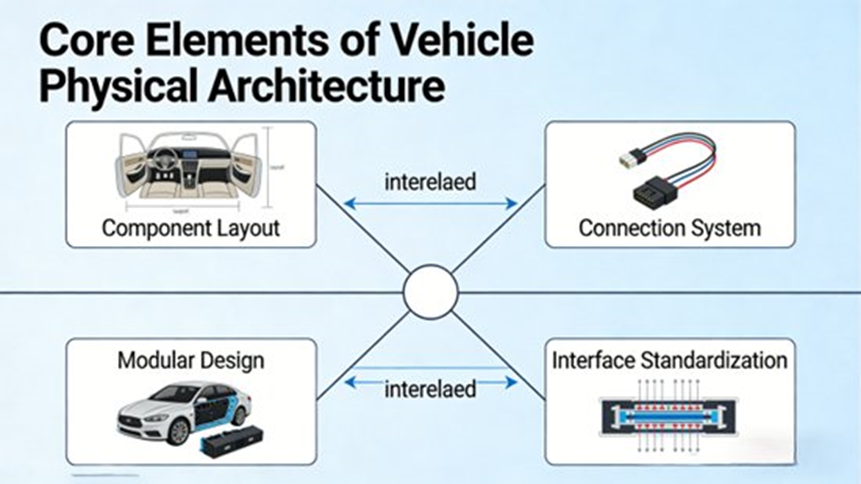
The Core Elements of Vehicle Physical Architecture (VPA)
Vehicle Physical Architecture (VPA) serves as the physical foundation for system integration. It is a structural layout that provides a stable installation base, efficient wire routing, and a proper working environment.
The four core elements include:
- Component Layout: Spatial planning of engines, batteries, motors, and computers, balancing weight distribution, center of gravity (CG), and space utilization.
- Connection Systems: Routing and protection of wiring harnesses and pipelines (hydraulic, cooling, pneumatic), which directly affect signal speed and fluid flow.
- Modular Design: Grouping related parts into modules (like power, cockpit, or ADAS) to boost R&D speed and lower costs.
- Interface Standardization: Defining mechanical, electrical, and communication connections to ensure parts are interchangeable and ready for future upgrades.
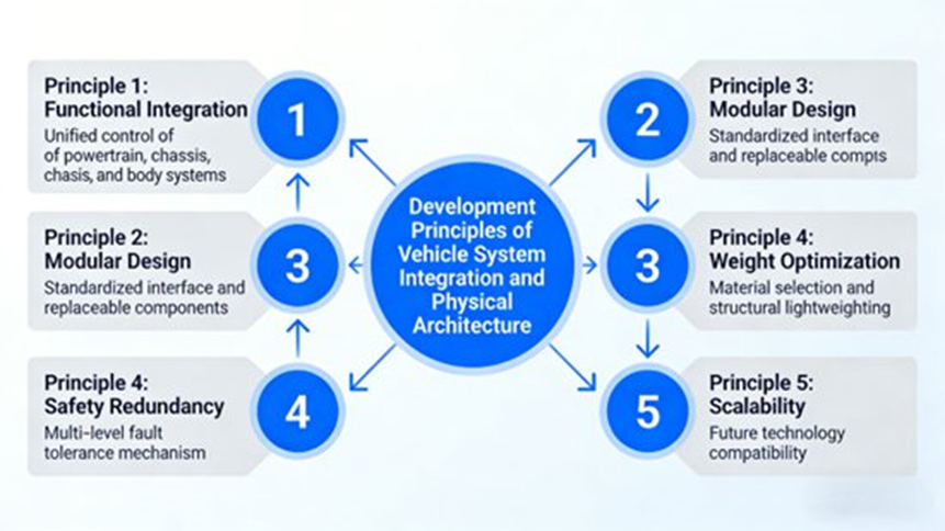
5 Fundamental Principles Guiding Architecture Development
To keep designs practical and ready for future updates, architecture development must follow five core principles:
- The Systemic Principle: Look at the whole car to avoid making one part perfect while ruining the rest. For instance, EV battery placement must account for installation space, cooling, CG height, an ideal 50:50 front-to-rear axle weight ratio, and proximity to motors. Keeping high-voltage cables short reduces EMC risks. Engineers rely heavily on system simulations via ADAS and MATLAB/Simulink here.
- The Collaborative Principle: Break down walls between engineering teams. Wiring harness routing must match electrical bandwidth needs (CAN FD, Ethernet), body structures (pass-through holes), and chassis movements (steering/suspension paths) to stop physical chafing. Platforms like PREEvision and CATIA make this team synchronization possible.
- The Scalability Principle: Leave physical space and digital connections open for rapid tech updates. ADAS layouts must physically hold future LiDAR and radar units to upgrade from L2 to L4 autonomous driving. Electronic setups need domain controllers with room to grow their computing power.
- The Reliability Principle: Keep the vehicle stable long-term. Place critical ECUs and sensors far away from intense heat, vibration, and humidity. Shield high-voltage cables from wear and tear, and route fluid pipes without sharp bends. Rigorous high/low-temp and vibration testing confirms these choices.
- The Economic Principle: Balance performance and cost without over-engineering. Shorter wiring saves material and labor. Modular designs drop R&D and supply chain expenses. Simple layouts lower lifecycle maintenance bills for the end user.
Key Technologies Driving Vehicle System Integration
1. Modular Integration Technology
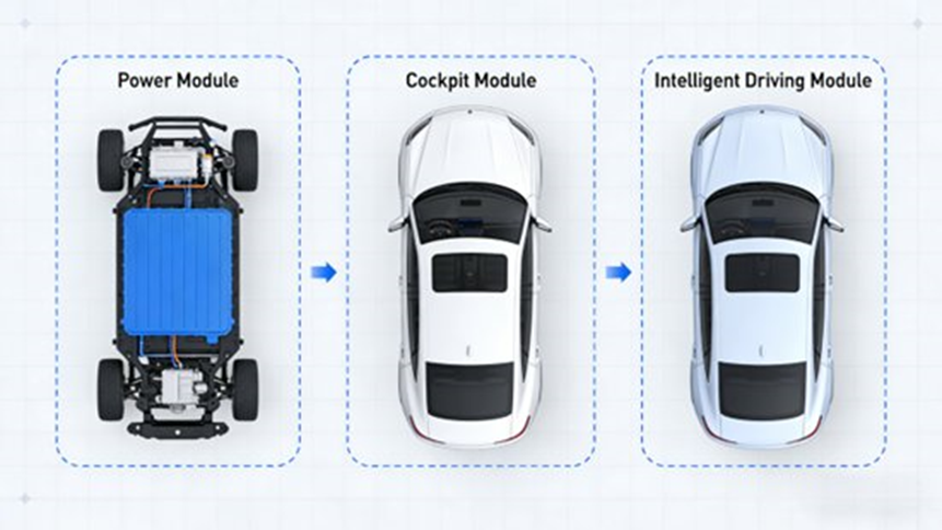
This method divides the vehicle into specific functional blocks.
- Module Division: An EV powertrain module combines the battery pack, motor, electronic controls, and cooling system into one unit. A cockpit module groups the dashboard, central screen, HVAC, and seats.
- Interface Standardization: Using standard mechanical brackets and communication protocols (CAN FD, Ethernet) creates plug-and-play capability.
- Pre-integration Validation: Teams bench-test these modules for power output and thermal behavior before assembling the full vehicle.
2. Domain Controller Architecture (DCA) Integration
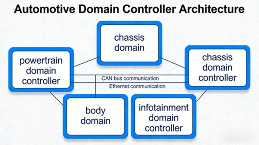
Moving away from dozens of small, scattered ECUs to a few powerful functional domains solves wire bloat and data traffic jams.
- Domain Division: Grouping by function. The Powertrain domain needs millisecond real-time reactions. The ADAS domain requires massive computing and bandwidth for cameras and LiDAR. The Cockpit domain handles user experience and infotainment.
- Controller Selection & Layout: Engineers select high-compute chips (like Nvidia Orin-X or Horizon Journey 5) for ADAS and mount them near the front or cabin rear to shorten sensor cable runs. Powertrain controllers sit closer to the battery or engine compartment.
- Inter-Domain Synergy: High-speed Ethernet buses let different domains talk. The ADAS domain can easily send acceleration and braking commands straight to the powertrain and chassis domains.
3. Wiring Harness Optimization and EMC Control
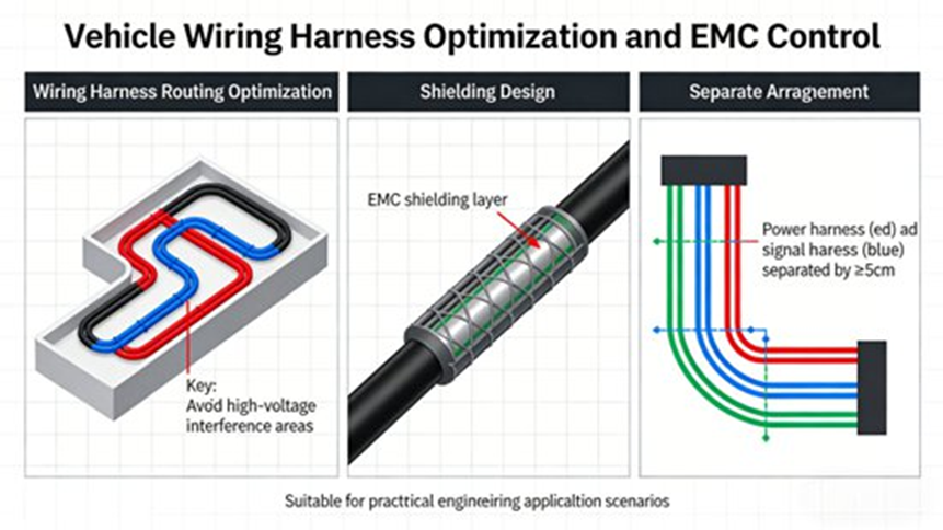
Think of the wiring harness as the car’s nervous system. It requires meticulous planning.
- Optimization Strategies: Group cables by domain, route them along body frames away from exhaust heat and moving parts, and use integrated modular harnesses. This cuts down on the number of connectors and reduces overall weight.
- EMC Control: Electromagnetic Compatibility requires metal or aluminum foil shielding on high-voltage lines. Engineers maintain strict physical distance between high-voltage power cables and low-voltage signal wires, while setting up reliable grounding points. Sensitive ECUs get their own protective shielding enclosures.
4. Thermal Management System Integration
Controlling the temperatures of the battery pack, motor, and electronics stops degradation and keeps EVs running safely.
- Modular Design: Powertrain parts share cooling loops, water pumps, and radiators to save space.
- Packaging Optimization: Radiators sit at the front to catch maximum airflow. Cooling pipes spread evenly inside the battery pack to stop hot spots from forming.
- Software Strategy: The system adjusts dynamically based on vehicle load and speed. It scavenges waste heat from the motor to warm the cold battery in winter. In summer, the software focuses heavily on battery cooling to stop thermal runaway.
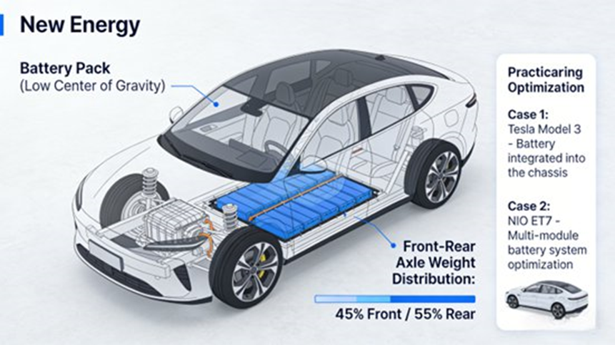
5. Center of Gravity (CG) and Weight Distribution Optimization
- Strategic Layout: Engineers place heavy items centrally and low to the ground. EV batteries make up 20% to 30% of total vehicle weight, so putting them under the floor creates a low CG and a near 50:50 front-to-rear axle ratio. This vastly improves handling and stability.
- Lightweighting Integration: Mixing high-strength steel with aluminum alloys for the body shell sheds weight. Using aluminum and carbon fiber for chassis parts reduces unsprung mass.
- Validation: Teams verify these layouts using dynamics simulation software (ADAMS) combined with physical handling tests on the track.
The 5-Stage Implementation Process for Physical Architecture
- Requirements Analysis and Architecture Planning: Teams gather market, user, and safety targets (like EV range, ADAS level, and crash safety). They map out size, weight, cost, and manufacturing limits to output the main architectural plan.
- Concept Design: Engineers translate those plans into preliminary 3D packaging. They use 3D modeling tools (like CATIA) to check for physical interference, weight distribution, and wire routing feasibility.
- Detailed Design: The team finalizes exact coordinates, mounting brackets, and specific fluid routings. They write strict interface standards and run multi-disciplinary reviews across mechanical, electronic, software, and production teams.
- Integration and Verification: Testing moves from individual module bench tests to sub-system integration. Finally, the full vehicle undergoes road handling, EMC, and durability testing to verify complete system harmony.
- Iterative Optimization: A continuous feedback loop takes test results, market data, and factory assembly feedback to refine the architecture for mass production and future technical upgrades.
Engineering Practices and Troubleshooting Guide
Best Practices for Successful Integration
- Multi-Disciplinary Synergy: Co-design parts across different engineering fields. An electronic engineer and a mechanical engineer must work together to find an ECU location that offers good signal transmission and enough cooling airflow.
- Simulation-Driven Design: Run CATIA for 3D packaging, ADAMS for movement paths, and MATLAB/Simulink/PREEvision for system communication before building any physical prototypes.
- Standardization & Manufacturability: Design the layout so factory workers can assemble it quickly on the line, and mechanics can easily reach parts for aftermarket repairs.
Common Architectural Problems and Expert Solutions
- Component Interference: Solution: Use highly precise 3D modeling and simulate suspension/steering movements early to carve out proper physical space for moving parts.
- EMC Exceedance: Solution: Force strict physical separation of HV and LV lines, create stronger ground connections, and add thicker shielding to sensitive electronics.
- Thermal Management Failures: Solution: Reroute cooling loops, install larger radiators and fans, and rewrite software algorithms to dynamically share heat loads.
- Wiring Harness Redundancy: Solution: Move basic functions into domain controllers and rely on standardized, integrated trunk harnesses to cut down on branch wires.
- Weight Imbalance: Solution: Shift heavy modules closer to the vehicle’s geometric center and replace standard steel with lightweight aluminum or composites in non-critical structural areas.
Frequently Asked Questions (FAQ) on Vehicle System Integration
1. Why is vehicle system integration becoming increasingly complex?
Short Answer: Vehicles now combine electric power, automated driving, and heavy software reliance all at once, multiplying the number of parts that must talk to each other flawlessly.
Modern vehicles integrate electrification, automation, connectivity, and software-defined features simultaneously. A single modern car may contain 100–150 electronic control units (ECUs) managing functions like ADAS, infotainment, powertrain, and body electronics. Each ECU requires communication networks and physical wiring, which rapidly scales up system complexity. On top of that, making AI algorithms and cloud connectivity work smoothly requires new hardware-software co-design methods to maintain functional safety and real-time performance.
2. What is the difference between traditional ECU architecture and domain/zonal architecture?
Short Answer: Traditional setups use one separate computer for every single vehicle function. Modern domain or zonal designs group systems by logic or physical location to save heavy wiring and boost computing speed.
As systems grow complex, the industry is transitioning away from distributed models:
- Traditional Distributed Architecture: One ECU runs one specific function. This causes a massive number of controllers, incredibly heavy wiring harnesses, and difficult software update paths.
- Domain Architecture: Functions are grouped logically into domains (Powertrain, Body, ADAS, Cockpit). A central domain controller manages each group, cutting down the total ECU count and making software integration much simpler.
- Zonal Architecture: Components group together based on their physical location in the vehicle rather than their logical function. This approach dramatically shrinks wiring length, simplifies network traffic, and sets the stage for ultimate centralized computing platforms.
3. Why is wiring harness optimization a major challenge in vehicle architecture?
Short Answer: Wiring is heavy, expensive to make, and hard to route through a car body, creating a huge physical and digital bottleneck for modern data-heavy vehicles.
The wiring harness is one of the largest, heaviest, and most intricate sub-systems in a car. It can span several kilometers and weigh tens of kilograms. As electronic components multiply, the harness grows rapidly. This causes increased vehicle weight, higher manufacturing costs, and tight packaging problems. Long wire paths also delay communication and increase the risk of Electromagnetic Interference (EMI). Engineers solve this by adopting Zonal E/E Architectures, modular harness designs, and Automotive Ethernet networks to handle data traffic efficiently.
4. How do modern vehicle architectures support Software-Defined Vehicles (SDVs)?
Short Answer: SDVs rely on software rather than hardware to define what a car can do, requiring powerful central computers and fast networks to run dynamic, over-the-air updates.
The Software-Defined Vehicle shifts the design paradigm so that code determines vehicle capabilities. Modern architectures enable this transformation through several tools:
- Centralized Computing Platforms: High-performance computers replace numerous smaller ECUs.
- Automotive Ethernet Networks: High-speed communication cables handle massive data streams coming from LiDAR, radar, and cameras.
- Adaptive Software Platforms: Systems like AUTOSAR Adaptive allow applications to run on powerful multicore processors and handle dynamic changes.
- Over-the-Air (OTA) Updates: Vehicles seamlessly receive software patches and feature upgrades post-production without visiting a dealership.
5. What are the biggest engineering challenges in vehicle system integration?
Short Answer: Engineers must solve technical hurdles like signal timing, bridge organizational barriers between different engineering teams, and manage the difficulty of building hardware and software at the same time.
Modern system integration challenges fall into three primary categories:
- Technical Challenges: Guaranteeing real-time communication, making safety-critical controls work together, passing Electromagnetic Compatibility (EMC) standards, and managing thermal heat loads.
- Organizational Challenges: Coordinating complex tasks across mechanical, electrical, and software engineering teams, while keeping OEM and supplier timelines aligned.
- Methodological Challenges: Managing hardware-software co-design and rapid feature iteration. To overcome this, modern development heavily relies on Model-Based Systems Engineering (MBSE), digital twins, and virtual validation environments.
The Future of Vehicle Architecture
Vehicle System Integration and Physical Architecture Development form the backbone of modern automotive R&D. By following systemic, scalable, and collaborative rules, engineers eliminate technical barriers to build safer, faster, and more cost-efficient cars.Looking ahead, the industry will move toward Centralized Computing Architecture, stepping past Domain Controllers to use a single “Central Brain.” This will drastically cut part counts and supply massive computing power for high-level autonomous driving. Architectures will also natively support Deep V2X Fusion, optimizing sensor layouts to talk seamlessly with city infrastructure and the power grid. As battery technology grows, engineers will integrate battery cells directly into the vehicle structure (CTC – Cell to Chassis technology) using advanced composite materials. Finally, the entire vehicle lifecycle will shift to Digital Twins and AI, allowing teams to simulate, test, and build cars in virtual spaces to cut costs and development time exponentially.
