

< Back to Automotive Simulation Toolchain
Author: Johnny Liu
Role: CEO at Dowway Vehicle
Published Date: March 12, 2026
Last Updated: March 12, 2026
Reading Time: 16 minutes
Content Type: Technical cluster page
Editorial Note
We built this article from a full technical source report focused on Altair HyperMesh Simulation Platform (Chinese Edition) in automotive engineering. We expanded the content for search readability and structured relevance while keeping the original report’s technical scope, engineering logic, workflow order, case-study data, operational details, quality indicators, solver references, and application scenarios.
Our goal is to present this material in a format that engineers can scan and technical decision-makers can trust. We removed language barriers and organized the application content into repeatable workflow blocks.
- Why Altair HyperMesh for Automotive Engineering Matters
- What Is Altair HyperMesh for Automotive?
- The Core Value of HyperMesh Chinese Edition in Automotive Programs
- How HyperMesh Fits Into the Automotive Development Lifecycle
- Geometry Processing for Automotive Models
- Mesh Generation: The Core Accuracy Foundation of Automotive CAE
- Simulation Model Setup for Automotive Applications
- Post-Processing: Turning Results Into Engineering Decisions
- Case Study 1: Body-in-White Lightweight Optimization
- Case Study 2: Chassis Control Arm Fatigue Life Analysis
- Case Study 3: NVH Optimization for Vehicle Comfort
- Practical Engineering Guidance and Common Risks
- Future Outlook: AI, Electrification, and Next-Generation Automotive CAE
- Frequently Asked Questions About Altair HyperMesh in Automotive CAE
Why Altair HyperMesh for Automotive Engineering Matters
The CAE toolchain connects product design and mass production in digital automotive R&D. It links CAD design, simulation preparation, performance verification, design iteration, and engineering decision-making in one workflow. Within this chain, Altair HyperMesh Simulation Platform (Chinese Edition) acts as a critical piece because it combines fast finite element modeling, multi-physics simulation adaptability, and full-process engineering compatibility.
As a core module within the Altair HyperWorks platform, HyperMesh Chinese Edition is more than a translated interface. It matches Chinese automotive engineering standards and local OEM and supplier development processes. In major automotive scenarios such as body structure optimization, chassis performance simulation, crash safety analysis, and NVH optimization, it serves as the primary platform for model preprocessing, simulation setup, and result post-processing.
Altair HyperMesh for automotive goes beyond standard meshing. It is a central engineering platform that improves development efficiency, simulation accuracy, and cost control throughout the vehicle development cycle.
What Is Altair HyperMesh for Automotive?
Altair HyperMesh is a professional finite element simulation platform for advanced industries such as automotive and aerospace. In automotive engineering, it serves as a full-process CAE preprocessing and post-processing solution.
It removes the barriers between design and simulation. Engineers move smoothly from CAD import to simulation-ready finite element models, and then to analysis results and design improvement. This directly solves common automotive R&D problems, including:
- complex product geometry
- poor mesh quality
- long simulation preparation cycles
- difficult multi-software collaboration
- high physical prototype costs
Compared with the English version, the Chinese-localized version offers three major advantages.
First, it provides a fully localized Chinese interface and workflow. This reduces language barriers, lowers the training threshold, and fits the working habits of local engineering teams.
Second, it includes template libraries built around Chinese automotive industry standards. These templates cover body, chassis, and powertrain applications. They directly support mesh quality rules, material parameter libraries, and load conditions compatible with GB and QC requirements.
Third, it integrates deeply with the CAD tools and solvers commonly used in local automotive development, including CATIA, UG, SolidWorks, OptiStruct, Radioss, ANSYS, and Nastran. This reduces precision loss during data translation and speeds up engineering collaboration.
The Core Value of HyperMesh Chinese Edition in Automotive Programs
HyperMesh Chinese Edition brings value to automotive programs in three connected areas: usability, standardization, and workflow integration.
Usability comes first. A fully localized environment reduces learning friction, especially for engineers working with complex geometry cleanup, mesh generation, connection definitions, load setups, and result interpretation under strict project deadlines.
Standardization matters because automotive simulation requires repeatable engineering rules. Many local teams use internal standards built around national and industry requirements. Having templates and parameter libraries already matched to these workflows helps improve consistency.
Workflow integration keeps projects moving. Real projects involve data handoff across CAD teams, CAE analysts, subsystem engineers, test engineers, and program managers. A tool that minimizes translation errors and supports smooth model transfer has immediate practical value.
The platform supports the entire automotive development cycle:
- Concept design stage: supports simplified models and topology optimization for structural layout selection.
- Detailed design stage: supports high-quality meshing, connection definition, contact setup, and boundary condition assignment for static, dynamic, crash, and NVH studies.
- Validation and iteration stage: supports quick result review, defect localization, and design refinement.
Using HyperMesh Chinese Edition for CAE preprocessing can reduce the simulation cycle of automotive components by 30% to 50% and improve mesh quality pass rates by more than 25%.
How HyperMesh Fits Into the Automotive Development Lifecycle
At the concept stage, teams need fast structural studies even when geometry is still changing. HyperMesh supports simplified model creation and topology optimization, helping engineers explore the best structural layout early.
At the detailed design stage, engineering work requires precision. Models need realistic mesh quality, accurate connection definitions, correct loads, and well-organized solver-compatible data. HyperMesh handles full simulation model preparation for structural, crash, fatigue, and NVH analysis.
At the validation stage, engineers must locate weak regions quickly and feed design changes back to the CAD team. HyperMesh provides visual post-processing, data extraction, comparison tools, and report outputs to close the loop between design and simulation. This directly reduces the number of physical prototype iterations.
Geometry Processing for Automotive Models
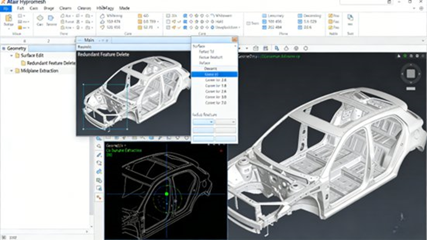
Geometry processing is the first major technical block in the workflow. Automotive CAD models often include non-essential geometric details, such as small fillets, small holes, decorative features, redundant surfaces, and local defects. If these details pass directly into CAE, they create large meshes, lower meshing speed, and reduce solver performance. HyperMesh provides dedicated geometry cleanup and simplification tools to fix this.
CAD Data Import
The platform supports common CAD formats such as:
- IGES
- STEP
- Parasolid
It can also directly import models from automotive design tools such as:
- CATIA
- UG
- SolidWorks
This preserves topology and reduces geometry damage caused by file conversion. The platform also features seamless PDM integration. Users can directly access internal enterprise model libraries and revision histories to maintain data consistency.
Automatic Geometry Cleanup
HyperMesh repairs common geometry problems such as:
- gaps
- overlaps
- missing surfaces
- incomplete topology
It stitches surfaces, deletes redundant features, and smooths complex automotive surfaces. This matters most in body panels such as doors and engine hoods, where surface continuity affects mesh quality. The software uses AI-driven automatic pattern and shape recognition to identify similar shapes and edit them together, cutting down repetitive work.
Model Simplification
Engineers can simplify models based on simulation needs. They keep core load-bearing structures while removing non-critical details such as:
- holes smaller than 5 mm in diameter
- fillets smaller than 3 mm in radius
For automotive sheet-metal parts such as body panels, HyperMesh extracts mid-surfaces. This step is mandatory for 2D shell meshing and greatly improves modeling speed.
Automotive Geometry Best Practices
For body models, keep major load-bearing parts such as frames, cross-members, and pillars. Simplify non-load-bearing items such as interior trim. For chassis components such as control arms and steering knuckles, preserve critical holes, welds, and connection features to avoid force-path distortion. Check the final model with built-in geometry verification tools to confirm there are no free edges, no overlapping surfaces, and no topological defects.
Mesh Generation: The Core Accuracy Foundation of Automotive CAE
Mesh generation dictates simulation accuracy. Different automotive components require different element types, mesh sizes, and quality controls. HyperMesh Chinese Edition supports 2D shell elements, 3D solid elements (tetrahedral and hexahedral), and 1D beam elements.
Element Selection by Automotive Part Type
- 2D shell elements: used for thin parts such as body panels and door structures. Typical mesh size: 5 to 10 mm.
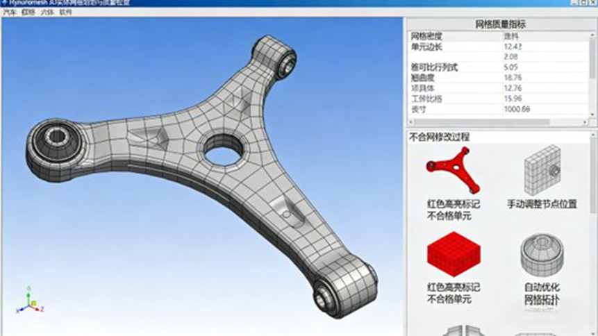
- 3D solid elements: used for load-bearing components such as chassis control arms, steering knuckles, and engine block structures. Typical mesh size: 2 to 5 mm.
- 1D beam elements: used for slender parts such as vehicle frames and transmission shafts to simulate load transfer.
Automated Meshing
HyperMesh includes automotive-specific meshing templates for body, chassis, and powertrain components. It supports mixed quadrilateral and triangular shell meshing. A strict rule applies here: keep triangular elements below 15% of the shell mesh. Unless geometry makes it unavoidable, never allow more than two adjacent triangular elements.
Mesh Quality Control
HyperMesh provides quality checks for key metrics and uses color mapping to locate poor mesh regions. Practical quality targets include:
- warpage ≤ 15
- aspect ratio ≤ 5
- Jacobian ≥ 0.6
For crash simulations, apply local refinement in key areas such as body crash energy absorption zones, front longitudinal rails, bumper structures, and chassis connection regions. The platform supports multi-core parallel mesh generation for large full-vehicle models.
Automotive Meshing Best Practices
For crash simulations, front rails and bumpers require refined meshes around 2 to 3 mm to capture deformation and energy absorption. For NVH simulations, large panels such as floor structures need uniform mesh sizes. Sudden size transitions cause vibration-response errors. Always run a formal mesh quality acceptance check before moving forward.
Simulation Model Setup for Automotive Applications
HyperMesh supports full simulation model definition across multiple automotive scenarios, including statics, dynamics, crash safety, NVH, fatigue, and optimization.
Material and Property Definition
The built-in automotive material libraries cover high-strength steel, aluminum alloys, plastics, and rubber. Assign standard material properties such as elastic modulus, Poisson’s ratio, and yield strength. It also supports layered material definitions for composite structures such as carbon-fiber body components.
Connection and Contact Definition
Joints dictate stiffness, durability, vibration transfer, and crash load paths.
- Spot welds: modeled using connectors containing all welded layer information. The welded edge must contain at least two rows of elements.
- Bolted joints: modeled using RBE2 plus BAR elements.
- Adhesive joints: modeled using solid adhesive elements.
The platform handles different contact definitions, such as flexible contact in crash analysis and rigid contact in certain NVH workflows.
Loads and Boundary Conditions
HyperMesh supports standard automotive loading scenarios:
- full-vehicle gravity loads
- road loads during driving
- impact loads during collisions
- excitation loads for NVH analysis
It manages batch creation and editing of boundary conditions. Subsystem-level management improves efficiency when multiple components and load cases are involved.
Solver Integration
HyperMesh integrates with Altair solvers:
- OptiStruct for structural optimization
- Radioss for explicit dynamics and crash simulation
- AcuSolve for fluid simulation
It also supports third-party solvers such as ANSYS, Abaqus, and Nastran. Teams can export formats such as .bdf, .fem, and .inp to reduce data loss during handoff.
Post-Processing: Turning Results Into Engineering Decisions
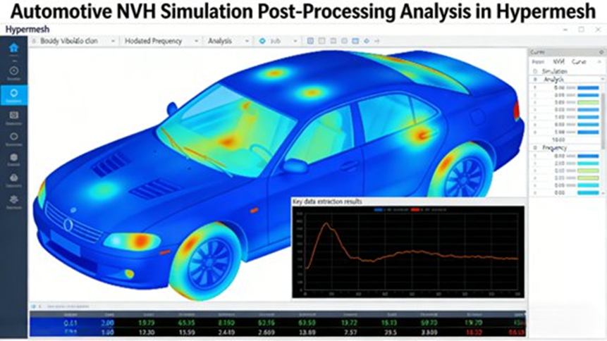
Post-processing answers engineering questions, locates weak points, and guides optimization.
Result Visualization
The platform creates contour displays for stress, strain, displacement, velocity, and acceleration. Animation-based review makes it easy to understand crash deformation and NVH vibration behavior. Section cuts extract local stress or strain results to locate hotspots like body pillars or chassis joints.
Data Extraction and Analysis
Extract key engineering values such as maximum stress, maximum displacement, natural frequencies, and energy absorption. Compare stress results across design alternatives or before and after lightweight optimization. AI-driven data analysis combines historical finite element data and geometric deep learning to provide fast physical predictions.
Report Generation and Export
Generate custom engineering reports including geometry model snapshots, mesh quality summaries, simulation parameters, result interpretations, and optimization recommendations. Export to Word, Excel, or PDF. The platform links results back to CAD locations so teams can modify the exact design region.
Post-Processing Best Practices
For body strength analysis, focus on stress concentration zones such as door hinge regions and body pillars. If stress exceeds material yield strength, change structural sizes or add reinforcements. For NVH work, compare natural frequencies with excitation frequencies to spot resonance risks, then adjust stiffness or damping material.
Case Study 1: Body-in-White Lightweight Optimization
A domestic OEM needed to reduce the weight of a compact sedan body-in-white while maintaining strength, stiffness, and crash safety.
Step 1: Geometry Processing
Engineers imported the CAD model, removed redundant details (small chamfers, decorative holes), extracted mid-surfaces, and repaired surface gaps. AI-based shape recognition identified similar structures automatically.
Step 2: Mesh Generation
They created a 2D shell mesh. They used a 5 mm mesh size for core load-bearing structures and an 8 to 10 mm mesh size for non-load-bearing areas. They controlled warpage (≤ 15) and Jacobian (≥ 0.6). The total mesh count reached roughly 150,000 elements.
Step 3: Simulation Setup
They assigned high-strength steel properties, defined weld points, and applied gravity, bending, and torsional loads. They used OptiStruct for static structural analysis and ran separate crash analyses.
Step 4: Optimization Iteration
Engineers applied topology optimization to low-stress areas to remove material and added reinforcements in stress concentration regions.
Results
The optimized body-in-white achieved:
- 8.5 kg weight reduction
- 5.2% lightweighting rate
- 3.8% improvement in bending stiffness
- 4.1% improvement in torsional stiffness
Crash performance satisfied GB 20071-2006. The project reduced development cost and cut the timeline by about 40 days.
Case Study 2: Chassis Control Arm Fatigue Life Analysis
A supplier needed to validate the fatigue durability of a chassis control arm using HyperMesh, Nastran, and Femfat.
Step 1: Geometry Processing
Engineers preserved connection holes and welds while simplifying non-critical chamfers. They extracted mid-surfaces for sheet-metal-like regions.
Step 2: Mesh Generation
They created a 3D solid mesh with a 2 to 3 mm size and refined the mesh around holes and welds. The model size was about 80,000 elements.
Step 3: Simulation Setup
They used aluminum alloy properties and modeled bolted joints with RBE2 plus BAR elements. They applied vertical and lateral road loads, ran a Nastran dynamic analysis, and sent the stress time-history data into Femfat.
Step 4: Analysis and Optimization
They located fatigue-critical regions around connection holes, increased local hole dimensions, added reinforcement rings, and reran the simulation.
Results
Fatigue life improved from 2.5 × 10⁵ cycles to 5.2 × 10⁵ cycles, meeting the 100,000 km durability target. The redesign lowered manufacturing cost and improved product qualification rates by over 20%.
Case Study 3: NVH Optimization for Vehicle Comfort
An SUV program suffered from high idle vibration and cabin noise.
Step 1: Geometry and Mesh Preparation
The team imported CAD data for the body, chassis, and engine bay. They used 2D shell elements (5 to 8 mm) for the body and 3D solid elements for engine-bay components.
Step 2: Simulation Setup
They defined elastic modulus, damping characteristics, and acoustic absorption coefficients. They applied engine idle and road excitation loads. They used Radioss for dynamic response analysis and acoustic simulation to map cabin noise.
Step 3: Result Analysis
They reviewed body vibration and cabin noise contour maps. They located problem areas near the engine bay floor panels and compared excitation frequencies against structural frequencies.
Step 4: Optimization Measures
The team added damping pads to body panels, adjusted chassis suspension stiffness, and improved engine-bay sound insulation.
Results
The optimized design achieved:
- 35% reduction in idle body vibration acceleration
- 4.2 dB(A) reduction in cabin noise
Performance met GB/T 25982-2010. The changes saved about 1.2 million RMB by avoiding repeated physical prototype builds.
Practical Engineering Guidance and Common Risks
1. Keep Geometry Simplification Reasonable
Balance speed and accuracy. Over-simplification damages results. Under-simplification increases mesh sizes. Clean up large body-in-white assemblies region by region.
2. Control Mesh Quality Strictly
Crash and fatigue studies require perfect mesh quality. Watch warpage, aspect ratio, and Jacobian values closely. Establish internal mesh quality standards to keep team outputs consistent.
3. Match Connection Modeling to Reality
Make sure welds, bolts, and adhesive joints mirror the real manufacturing process. Incorrect joint modeling distorts load paths.
4. Manage Multi-Software Compatibility
When moving data between HyperMesh, CAD systems, and external solvers, check version compatibility. Use HyperMesh’s Python scripting to automate custom operations.
5. Focus Post-Processing on Decisions
Extract the most useful data. Document assumptions, quality metrics, and optimization recommendations clearly so the design team knows exactly what to change.
Future Outlook: AI, Electrification, and Next-Generation Automotive CAE
The automotive industry moves fast toward electrification, intelligence, and lower vehicle weights. HyperMesh meets this shift with local usability, engineering depth, and AI support. AI-driven geometry recognition and result prediction reduce manual labor. The platform is expanding into new-energy scenarios, including power battery pack simulation and electric motor vibration analysis. As AI and CAE merge, HyperMesh will continue to deliver speed, accuracy, and support for modern automotive design.
Frequently Asked Questions About Altair HyperMesh in Automotive CAE
1. What is Altair HyperMesh and what is it mainly used for in automotive engineering?
Short Answer: Altair HyperMesh is a finite element modeling platform used to prepare simulation-ready models and review engineering results.
Details: It is widely used for body-in-white structural analysis, crash simulations, NVH analysis, chassis fatigue analysis, and lightweight design. It acts as the bridge between CAD design and CAE solvers.
2. Why is mesh quality so important in HyperMesh simulations?
Short Answer: Mesh quality directly determines the accuracy and speed of the CAE solver results.
Details: Poor mesh quality causes incorrect stress predictions and numerical instability. Important indicators include aspect ratio, warpage, and Jacobian values. HyperMesh includes automatic optimization tools to keep elements within acceptable engineering limits.
3. What is the typical workflow for building a simulation model in HyperMesh?
Short Answer: The standard process goes from CAD import to mesh generation, load setup, and solver export.
Details: The steps include CAD import, geometry cleanup, mesh generation, material and property definition, connection setup, load and boundary condition definition, solver export, and finally post-processing.
4. What are the most common problems beginners encounter in HyperMesh?
Short Answer: Beginners often struggle with invisible models, disabled tools, and geometry errors blocking the mesh.
Details: These issues usually happen due to incorrect working module selection, unhealed geometry defects, or wrong solver profile settings. Fix them by checking the active module, stitching free edges before meshing, and confirming the correct solver profile.
5. Why do automotive companies prefer HyperMesh for CAE simulation?
Short Answer: It handles large complex assemblies easily and works with almost any major solver on the market.Details: Automotive companies rely on it for its advanced meshing capabilities, strong support for full-vehicle models, Python scripting automation, and new AI-assisted modeling tools. It fits naturally into enterprise engineering workflows.
