

< Back to Platform Development
Author: Johnny Liu, CEO at Dowway Vehicle
Published Date: March 4, 2026
Read Time: Approx. 15 minutes
Introduction
As the automotive industry moves quickly toward electrification, intelligence, and lighter weights, and as traffic safety rules grow stricter, the brake subsystem has changed. It is no longer just a basic mechanical setup for slowing down and stopping. Today, it acts as an integrated hub combining active safety, energy recovery, and Noise, Vibration, and Harshness (NVH) management. How engineers select and design a brake subsystem directly dictates vehicle stopping distance, stability, energy consumption, and manufacturing costs. This guide systematically looks at the core classifications, selection rules, key design elements, and vehicle-specific setups of the automotive brake subsystem, giving you actionable references for engineering design.
- 1. Core Classifications of the Brake Subsystem
- 2. Engineering Principles for Brake Subsystem Selection
- 3. Key Design Elements of a Brake Subsystem
- 4. Brake Subsystem Adaptation by Vehicle Architecture
- 5. Brake Subsystem Troubleshooting and Future Trends
- 6. Frequently Asked Questions (FAQ)
- Final Engineering Thoughts
1. Core Classifications of the Brake Subsystem
Understanding the structural and energy-source variations is the first step in brake subsystem engineering.
1.1 By Actuation Energy Subsystem
This classification determines the power output capacity. Therefore, engineers must think about this first based on vehicle tonnage.
- Manual/Human-Powered: Relies solely on the driver’s pedal force. Due to limited braking force, modern mainstream vehicles mostly abandoned this, using it only as an emergency backup.
- Servo-Assisted: Uses engine intake manifold vacuum (vacuum booster) or a hydraulic pump to amplify pedal force. Vacuum boosters come standard for 1.0-2.5L passenger cars. Hydraulic boosters suit larger displacement vehicles, keeping performance stable and reducing driver fatigue.
- Power Braking: Relies entirely on external energy.
- Pneumatic (Air): Operates at 0.6-0.8MPa. With massive braking force and low maintenance, it works perfectly for medium/heavy commercial vehicles handling tens of tons. However, its slower response requires dual-circuit redundancy.
- Hydraulic: Converts pedal force into hydraulic energy via Pascal’s principle. With rapid response, it forms the foundation for over 95% of mass-produced passenger cars, keeping stopping distances under 40m at 100km/h on dry pavement.
- Regenerative Braking: Exclusive to New Energy Vehicles (NEVs). It converts kinetic energy into electrical energy stored in the battery. It can recover 30%-50% of braking energy, boosting driving range by 15%-25% while heavily reducing friction pad wear.
1.2 By Foundation Brake Subsystem Structure
The foundation brake is the core execution unit. It directly affects heat dissipation and NVH.
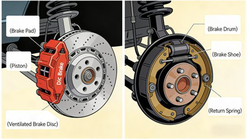
- Drum Brakes: Consist of a drum, shoes, wheel cylinder, and return springs. They offer immense braking torque due to a high lever ratio and low cost, making them ideal for the rear wheels of commercial vehicles. However, their closed structure limits heat dissipation, causing thermal fade during continuous braking. Configurations include leading/trailing, dual-leading, and self-energizing types.
- Disc Brakes: Comprise a disc, caliper, friction pads, and pistons. Floating calipers are compact and widely used. Fixed calipers offer superior stability at a higher cost. Their open structure provides excellent heat dissipation, rapid response, and automatic gap compensation. Discs fall into solid and vented categories (vented discs have radial holes for better cooling), making them highly suitable for high-speed, high-frequency braking.
2. Engineering Principles for Brake Subsystem Selection
Selection must avoid “performance surplus” or “under-adaptation” by following four core rules.
2.1 The Adaptability Principle
- Tonnage Matching: Passenger cars use hydraulic + disc/drum setups. A 49-ton heavy truck, which requires a continuous braking power exceeding 500kW, needs large pneumatic drum brakes (rear) and disc brakes (front).
- Operating Conditions: Urban cars focus on response and comfort (vacuum servo + all-disc). Mountainous commercial vehicles need thermal resistance (pneumatic + vented disc + retarder). NEVs require synergy between regenerative and mechanical braking.
- Powertrain Parameters: High-performance cars need large discs and ceramic pads. Low-speed EVs can utilize simplified hydraulic drum setups to cut costs.
2.2 The Safety Principle (Regulatory Compliance)
- Efficacy Standards: Must meet standards like GB 7258. Passenger cars at 100km/h must stop within 40m (max deceleration $\ge$ 5.9m/s²). Commercial vehicles at 50km/h must stop within 20m. Electronic aids (ABS/EBD) can shorten emergency distances by 10%-20%.
- Redundancy: Dual-circuit layouts are mandatory. If one circuit fails, the other must provide at least 30% of normal braking force (e.g., diagonal layout in passenger cars).
- Anti-Thermal Fade: Continuous braking pushes disc temperatures over 600°C. High-heat scenarios require vented discs and ceramic pads. Mining trucks may need added cooling fins and air ducts.
2.3 The Economic Principle
Balance performance with cost. Economic cars use front-disc/rear-drum configurations. Commercial vehicles rely heavily on rear drum brakes because they cost significantly less to maintain than disc brakes. Utilizing standardized, industry-wide components (like standard brake pipes) further cuts production costs.
2.4 The Reliability Principle
Material selection dictates environmental resistance. Brake discs often use HT250 gray cast iron or compacted graphite iron (which improves thermal cracking resistance by 30%). Pads utilize copper-free NAO materials (metal content $<$ 5%), maintaining a stable friction coefficient of 0.38±0.02 at 350°C. Pipes use dual-layer steel or high-strength nylon.
3. Key Design Elements of a Brake Subsystem
3.1 Foundation Brake Subsystem Design
- Disc Brakes: Passenger car discs range from 280-350mm in diameter; commercial sizes go from 350-500mm. Solid discs are 15-25mm thick, while vented are 25-40mm. High-performance vehicles may use carbon-ceramic composite materials (density 2.4g/cm³, heat resistance 1200°C). The target friction coefficient sits between 0.35-0.45.
- Drum Brakes: Commercial drum internal diameters usually measure 350-450mm with a shoe wrap angle of 100°-120° and thickness of 15-20mm. Automatic gap adjusters must maintain a compensation limit of $\le$ 0.2mm to guarantee consistent response.
3.2 Transmission and Actuation Subsystem Design
- Master Cylinder: Hydraulic cylinders typically feature a 20-25mm bore and 15-25mm stroke. Passenger cars use tandem dual-chamber cylinders.
- Piping: Pneumatic pipes must withstand $\ge$ 1.2MPa. Pipeline layouts must minimize length differences to keep braking lag under 0.3s (often assisted by quick-release valves).
- Boosters: Vacuum booster ratios generally hit 3-5 times the pedal input. Engineers must carefully calibrate the kick-in point and max assistance to ensure optimal pedal feel.
3.3 Auxiliary and Control Subsystem Design
- Electronic Controls: ABS requires a response time of $\le$ 10ms to prevent wheel lockup via pressure modulation. EBD dynamically adjusts front/rear braking force distribution based on payload, shortening distances by 5%-10%. BA detects emergency inputs and amplifies force.
- Retarder Subsystems (Commercial): Includes engine, exhaust, eddy current (providing 1000-5000N·m of torque), and hydraulic retarders (requiring oil temp management $\le$ 150°C).
- Regenerative Synergy (NEVs): Uses priority-layered control. At low speeds ($\le$ 30km/h), regen dominates. Threshold limits dictate action: if battery SOC is $\ge$ 80%, the system reduces regen to prevent overcharging; if SOC is $<$ 20%, the system maximizes regen.
3.4 Performance Verification and FEA Optimization
Engineering validation involves theoretical calculations, simulations, and real-world testing.
- Theoretical Math:
- Torque check: $T = m \times g \times a \times r$ (incorporating 0.85-0.95 efficiency and a 10%-15% safety margin).
- Distance check: $S = v_0 \times t_0 + v_0^2 / (2a)$ (where $t_0$ is usually 0.3s).
- Thermal check: Heat generation rate is modeled as $Q = 0.5 \times m \times v_0^2 / t$. Disc temp must stay $\le$ 600°C, pads $\le$ 350°C.
- Pedal force: Must be $\le$ 300N for passenger cars and $\le$ 500N for pneumatic commercial vehicles.
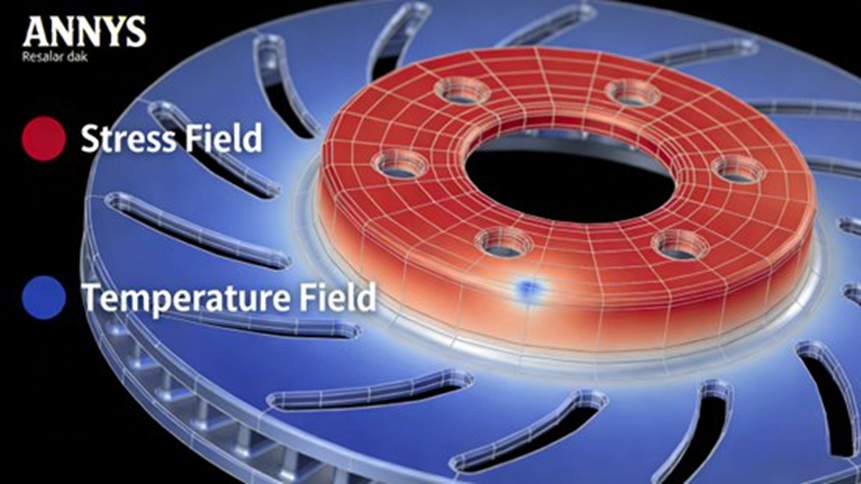
- Simulation: Using ANSYS and ADAMS for thermal/stress fields and multi-body dynamics. Optimizing vent hole arrays can reduce thermal stress by over 20%.
- Testing: Discs undergo 10,000 fatigue cycles without cracking. Pipes face 1.5x rated pressure testing. Fade tests require performance drops of no more than 20% after 10 continuous braking events on long descents.
4. Brake Subsystem Adaptation by Vehicle Architecture
4.1 Passenger Vehicles (Comfort & NVH)
Weighing 1-2.5 tons, the design focuses on urban agility. These setups utilize vacuum servo hydraulics with front vented (280-350mm dia, 15-35mm thick) and rear solid discs. NVH requires tight tolerances; disc flatness must be $\le$ 0.03mm. Target specs: 100km/h stopping $\le$ 40m, pedal force $\le$ 300N, fade drop $\le$ 15%.
4.2 Commercial Vehicles (Heavy Load & Reliability)
Weighing 2-49 tons, heavy trucks mandate pneumatic subsystems with robust storage (tanks $\ge$ 60L). A typical 49-ton truck uses 420mm front vented discs and 400mm rear drums paired with a hydraulic retarder. Target specs: 50km/h stopping $\le$ 20m, pedal force $\le$ 500N, enduring long descents with disc temps strictly under 550°C.
4.3 New Energy Vehicles (Energy Efficiency & Blending)
Weighing 1.2-2.8 tons, NEVs require electro-hydraulic synergy. High-precision pressure sensors dictate blending. In urban driving, regen can handle 60%-80% of light braking, yielding a 45% energy recovery rate and a 22% range boost. System lag during transition must be $\le$ 0.1s to prevent pedal shudder.
5. Brake Subsystem Troubleshooting and Future Trends
5.1 Solving Common Engineering Issues
- Insufficient Torque: Recalculate parameters, increase disc/drum size, upgrade friction coefficients, or reduce pipe pressure loss.
- Severe Thermal Fade: Upgrade to vented discs or ceramic/NAO pads, and integrate retarders for heavy-duty applications to reduce foundation brake load.
- Brake NVH/Noise: Improve machining precision (flatness/runout), tighten components, and add noise-dampening shims behind the pads.
- Brake Pulling: Calibrate EBD algorithms, ensure uniform hydraulic pressure left-to-right, and correct wheel alignment geometry (toe-in/caster).
- Rough Regen Blending: Refine control algorithms syncing speed, SOC, and pedal stroke, and calibrate sensors to eliminate transition jerks.
5.2 Where the Industry is Heading
- Lightweighting: Carbon-ceramic discs can cut weight by over 50% compared to cast iron.
- Intelligence: Engineers are integrating autonomous driving systems for adaptive braking and using IoT for predictive maintenance.
- Integration: The shift toward Brake-by-Wire (BbW) and integrated calipers combines foundation, parking, and regen functions to simplify architecture and lower costs.
6. Frequently Asked Questions (FAQ)
Below are the most asked questions about automotive brake subsystems, complete with authoritative engineering explanations.
Q1: How does a car brake system work?
A vehicle braking system works mainly by converting mechanical force into hydraulic pressure, which then creates friction to stop the wheels.
Key steps in the braking process:
- The driver presses the brake pedal.
- The master cylinder converts mechanical force into hydraulic pressure.
- Brake fluid transfers this pressure through brake lines.
- Calipers push brake pads against rotating discs (or shoes against drums).
- Friction converts kinetic energy into heat, slowing the vehicle.
Q2: What are the main components of a brake subsystem?
A typical automotive brake subsystem contains several mechanical and hydraulic components working together to generate braking force:
- Brake pedal: The driver’s input device.
- Brake booster: Amplifies pedal force using vacuum or pumps.
- Master cylinder: Generates hydraulic pressure.
- Brake fluid reservoir: Stores brake fluid.
- Brake lines and hoses: Carry pressurized fluid.
- Calipers or wheel cylinders: Convert hydraulic pressure into mechanical force.
- Brake pads and discs (or shoes and drums): Create friction to stop the wheel.
- ABS sensors and controllers: Prevent wheel lockup during braking.
Q3: What is ABS (Anti-lock Braking System) and why does it matter?
The Anti-lock Braking System (ABS) prevents the wheels from locking during hard braking. It works by pulsing the brake pressure multiple times per second using wheel speed sensors and electronic control units.
Key benefits of ABS:
- Prevents wheel lockup during emergency braking.
- Allows drivers to maintain steering control.
- Reduces the risk of skidding.
- Improves stability on slippery surfaces.
Q4: Why do brakes overheat or experience “brake fade”?
Brake fade occurs when the braking system loses effectiveness due to excessive heat generated by friction. This high heat can cause the brake fluid to boil and form compressible bubbles.
Major causes include:
- Continuous braking on steep slopes.
- High-speed or performance driving.
- Poor heat dissipation from foundation brake components.
- Moisture-contaminated brake fluid leading to a “spongy” brake pedal.
Q5: What are the most common types of automotive brake systems?
Modern vehicles use several braking technologies depending on the vehicle design:
- Hydraulic Brakes: The most common system, using fluid to transmit force.
- Disc Brakes: Pads press against a rotating disc (rotor), offering strong stopping power and excellent cooling.
- Drum Brakes: Shoes press outward against a drum. Manufacturers typically place these on the rear wheels of older, economy, or commercial vehicles.
- Regenerative Braking: Found in EVs and HEVs to convert kinetic energy into electrical energy stored in the battery.
- Brake-by-Wire Systems: Electronic signals control braking instead of purely hydraulic connections, representing the future of integrated braking.
Final Engineering Thoughts
Designing and selecting an automotive brake subsystem requires a precise balance of adaptability, safety, economy, and reliability. From the hydraulic discs of a passenger EV maximizing range, to the pneumatic drums and retarders of a 49-ton truck navigating mountain passes, meticulous design—backed by rigorous FEA simulation and testing—is non-negotiable. As the industry moves forward, the subsystem will keep shifting toward smarter, lighter, and highly integrated architectures.
