

< Back to Automotive Simulation Toolchain
Author: Johnny Liu
CEO, Dowway Vehicle
Last Updated: March 2026
- Quick Answer
- Why CFD Simulation Matters in Modern Vehicle Development
- What Is MXsim CFD?
- MxSim CAE Platform Architecture
- Mx3D Geometry Modeling
- MxMesh Mesh Generation Technology
- GPU-Accelerated CFD Solver
- Physical Models Supported in Automotive CFD
- Typical Automotive CFD Simulation Workflow
- Geometry Preparation
- Mesh Generation
- Solver Setup
- Post-Processing
- Case Study 1: Passenger Car Aerodynamic Simulation
- Case Study 2: EV Battery Liquid Cooling Simulation
- Case Study 3: Engine Intake Port Simulation
- Best Practices for Automotive CFD Simulation
- MXsim CFD Compared With Traditional CFD Tools
- Future Trends in Automotive CFD
- Frequently Asked Questions About MXsim CFD
- Author
- Engineering Disclaimer
Quick Answer
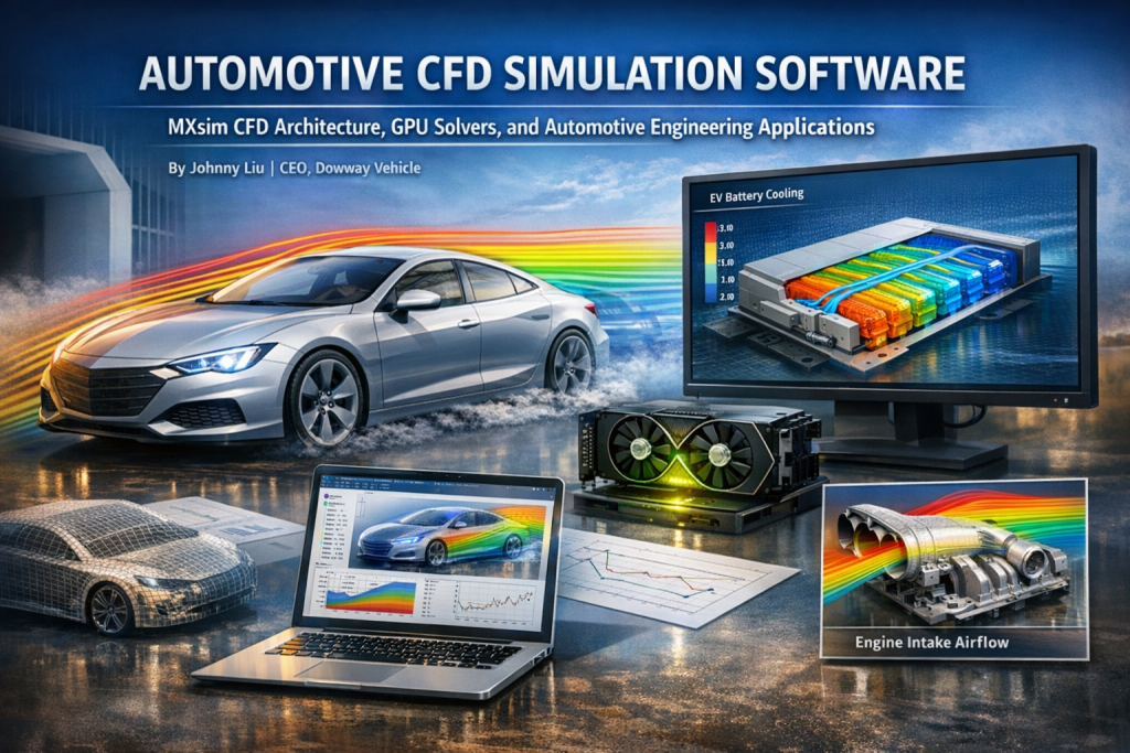
Automotive CFD simulation software helps engineers analyze airflow, heat transfer, and fluid movement inside vehicle systems using numerical simulation instead of physical testing. Platforms such as MXsim CFD combine geometry modeling, mesh generation, GPU-accelerated solvers, and result visualization to simulate vehicle aerodynamics, EV battery cooling, and engine intake airflow. This helps engineering teams reduce prototype costs and shorten development cycles.
Why CFD Simulation Matters in Modern Vehicle Development
Vehicle design has changed a lot over the past decade. Engineers now depend heavily on simulation before physical prototypes are built.
Several industry shifts drive this change:
- electric vehicle development
- lightweight vehicle structures
- intelligent vehicle systems
- pressure to reduce development time
In earlier development processes, fluid performance was measured mainly through physical testing:
- wind-tunnel experiments
- cooling performance testing
- airflow testing in engines
These tests are expensive and slow.
CFD simulation solves fluid equations numerically and predicts how air or coolant flows through vehicle components. Engineers can evaluate designs long before prototypes exist.
Typical automotive CFD applications include:
- external vehicle aerodynamics
- cabin ventilation
- cooling system design
- EV battery thermal management
- engine intake airflow
This is where simulation tools such as MXsim CFD become valuable.
What Is MXsim CFD?
MXsim CFD is part of the MxSim CAE simulation platform. It is designed for engineering simulation workflows that involve complex fluid behavior.
The platform integrates several stages of the CFD workflow into one environment.
The architecture includes four main modules.
MxSim CAE Platform Architecture
| Module | Function |
| Mx3D | Geometry modeling and CAD preparation |
| MxMesh | Mesh generation and refinement |
| MxSim CFD | Fluid solver |
| MxPost | Visualization and result analysis |
This structure allows engineers to complete the full simulation workflow without moving between different software tools.
Mx3D Geometry Modeling
The Mx3D module manages geometry preparation.
It supports common CAD formats such as:
- STEP
- IGES
The system also works with geometry from typical automotive CAD tools including:
- CATIA
- Siemens NX (UG)
Before simulation, engineers clean the geometry. Typical preparation steps include:
- removing small holes
- deleting unnecessary features
- fixing surface gaps
These operations prevent problems during mesh generation.
MxMesh Mesh Generation Technology
Mesh quality has a strong influence on CFD accuracy.
The MxMesh module creates computational grids for the solver.
Supported mesh types include:
- triangular surface mesh
- quadrilateral surface mesh
- tetrahedral volume mesh
- structured hexahedral mesh
In vehicle simulations, hybrid mesh structures are common.
Example mesh strategy:
| Vehicle Component | Mesh Type |
| Vehicle surface | quadrilateral mesh |
| Flow domain | tetrahedral mesh |
| Cooling channels | structured mesh |
MxMesh also supports:
- adaptive mesh refinement
- automatic node distribution control
- local mesh density adjustment
These features allow engineers to refine mesh density in important regions such as:
- vehicle body surfaces
- airflow channels
- cooling plates
The mesh generator uses OpenMP multi-threading, which increases mesh generation speed by about 30% compared with traditional tools.
Example performance result:
A 3.79-million-cell hybrid mesh can be generated in several tens of minutes.
GPU-Accelerated CFD Solver
The core component of MXsim CFD is the GPU-based solver.
Traditional CFD tools usually rely on CPU processing. GPU acceleration increases computational speed.
MXsim CFD uses:
- GPU instruction set optimization
- MPI parallel computing
- full GPU processing pipeline
Performance improvements include:
| Hardware Configuration | Speed |
| CPU baseline | 1× |
| Single GPU | about 10× faster |
| Four GPUs | up to 210× faster |
This allows simulations with hundreds of millions of mesh cells to be completed within practical engineering timelines.
Physical Models Supported in Automotive CFD
Automotive simulations require multiple physical models.
MXsim CFD includes several models commonly used in engineering practice.
Turbulence Models
Two turbulence models are widely used:
- k-ε turbulence model
- k-ω turbulence model
These models simulate turbulent airflow around vehicle surfaces.
Heat Transfer Models
Heat transfer modeling includes:
- convective heat transfer
- radiation heat transfer
These models are important for EV battery cooling analysis.
Multiphase Flow Models
The solver also supports multiphase flow simulations such as:
- liquid cooling systems
- coolant channel flow
- air-liquid interaction
Compressible and Incompressible Flow
The solver can simulate both flow regimes.
| Flow Type | Solver |
| Low-speed flow | pressure-based solver |
| High-speed flow | density-based solver |
Examples:
- vehicle aerodynamics → pressure-based solver
- engine intake airflow → density-based solver
Typical Automotive CFD Simulation Workflow
Vehicle CFD simulations follow several key steps.
Geometry Preparation
Automotive CAD models often contain excessive details.
Engineers typically simplify models by:
- removing tiny geometric features
- fixing surface defects
- extracting mid-surfaces
For symmetric vehicles, a half-vehicle model is often used to reduce mesh size and computational time.
Mesh Generation
Different systems require different mesh strategies.
Example configurations:
| Application | Mesh Type |
| Vehicle aerodynamics | hybrid mesh |
| Battery cooling | structured mesh |
| Engine intake | tetrahedral mesh |
Recommended mesh quality limits:
- skewness < 0.8
- aspect ratio < 10
Solver Setup
Boundary conditions should match real operating conditions.
Common CFD boundaries include:
- velocity inlet
- pressure outlet
- wall boundary
- symmetry boundary
- far-field boundary
Simulation convergence is usually defined as:
Residual < 1 × 10⁻⁶
Post-Processing
Simulation results are analyzed in MxPost.
Visualization outputs include:
- velocity streamlines
- pressure contour maps
- temperature distribution
- 2D performance curves
Engineers use these results to evaluate aerodynamic drag, cooling performance, and pressure loss.
Case Study 1: Passenger Car Aerodynamic Simulation
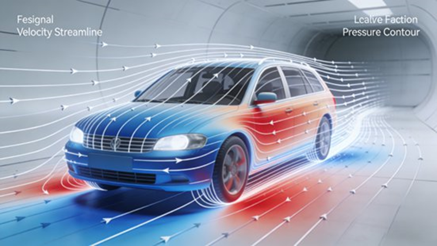
Short Answer
CFD simulation showed that adjusting the vehicle front grille angle, roof curve, and rear spoiler reduced drag from Cd 0.32 to 0.28, improving aerodynamic efficiency and extending EV driving range.
Simulation Objective
The goal was to evaluate the external airflow of a compact passenger vehicle and reduce aerodynamic drag.
Lower drag improves:
- fuel efficiency
- EV driving range
- wind noise performance
Simulation Conditions
| Parameter | Value |
| Air velocity | 10 m/s |
| Temperature | 293 K |
| Flow type | turbulent incompressible |
| Turbulence model | k-ε |
The simulation used a half-vehicle model.
Mesh Configuration
Mesh characteristics:
- hybrid mesh
- surface mesh refinement on vehicle body
- tetrahedral mesh in outer flow domain
Total mesh size:
3.79 million cells
Mesh generation time on RTX 3090 GPU:
≈ 15 minutes.
Simulation Results
Original design:
Cd = 0.32
After optimizing:
- grille angle
- roof curvature
- rear spoiler height
New result:
Cd = 0.28
Drag reduction:
12.5%
For electric vehicles, this can increase driving range by 5–8%.
Simulation comparison with Fluent showed error below 3%.
Case Study 2: EV Battery Liquid Cooling Simulation
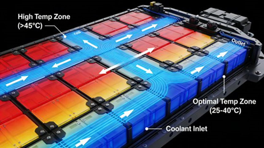
Short Answer
Simulation revealed that widening the coolant channel from 8 mm to 10 mm reduced maximum battery temperature from 45°C to 38°C and reduced temperature variation across cells.
Simulation Objective
The goal was to analyze the cooling performance of an EV battery pack.
Battery cells should operate within 20–40°C to maintain safety and performance.
Battery Model
The pack contained:
- 8 battery modules
- cooling plates
- coolant channels
- outer enclosure
The cooling plate used a serpentine flow channel.
Simulation Parameters
| Parameter | Value |
| Coolant | 50% glycol solution |
| Density | 1050 kg/m³ |
| Specific heat | 4200 J/(kg·K) |
| Inlet temperature | 25°C |
| Coolant velocity | 2 m/s |
| Battery heat | 200 W |
The enclosure used natural convection with heat transfer coefficient:
15 W/(m²·K).
Mesh Configuration
Mesh type:
structured hexahedral mesh.
Total mesh size:
4.8 million cells
Mesh generation time:
≈ 20 minutes on RTX 3090.
Simulation Results
Initial design:
Maximum temperature = 45°C
Temperature difference = 8°C
After design changes:
- coolant channel widened
- additional branches added
New result:
Maximum temperature = 38°C
Temperature difference = 3°C
Simulation error compared with physical tests was below 2°C.
Case Study 3: Engine Intake Port Simulation
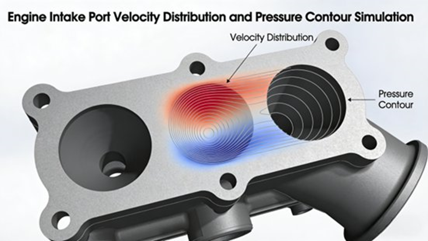
Short Answer
Optimizing the intake port bend radius and throat area reduced pressure loss from 0.18 to 0.12 and increased intake airflow by 15%.
Simulation Objective
Engine intake airflow affects combustion efficiency and fuel consumption.
CFD analysis helps engineers improve intake port design.
Simulation Setup
| Parameter | Value |
| Temperature | 293 K |
| Inlet velocity | 15 m/s |
| Outlet pressure | 0.8 atm |
Boundary conditions:
- velocity inlet
- pressure outlet
- no-slip wall boundary
Mesh Configuration
Mesh type:
tetrahedral mesh.
Total mesh size:
1.2 million cells
Mesh generation time:
≈ 8 minutes.
Simulation Results
Original design:
Pressure loss coefficient = 0.18
Design changes:
- bend radius increased from R50 mm to R70 mm
- throat area increased from 35 cm² to 40 cm²
New result:
Pressure loss coefficient = 0.12
Airflow increase:
15%
Fuel consumption improvement:
3–5%
Best Practices for Automotive CFD Simulation
Engineers follow several guidelines when preparing CFD models.
Geometry Preparation
- remove tiny holes
- delete unnecessary details
- repair surface gaps
These steps prevent mesh failures.
Mesh Quality Control
Recommended limits:
| Metric | Limit |
| Skewness | < 0.8 |
| Aspect ratio | < 10 |
Boundary Condition Setup
Boundary values must match real operating conditions.
Incorrect inputs can produce misleading simulation results.
Solver Stability
If the solver fails to converge, engineers should check:
- mesh quality
- boundary settings
- relaxation parameters
Hardware Recommendations
GPU acceleration requires compatible hardware.
Recommended GPUs:
- NVIDIA RTX 3090
- NVIDIA RTX 4090
MXsim CFD Compared With Traditional CFD Tools
Short Answer:
MXsim CFD delivers similar accuracy to Fluent while reducing simulation time through GPU acceleration and lowering licensing cost.
MXsim advantages include:
- GPU-accelerated solver
- faster simulation speed
- localized interface
- lower licensing cost
- automotive simulation templates
Simulation accuracy differences compared with Fluent are typically below 3–4%.
Future Trends in Automotive CFD
Vehicle simulation tools continue to evolve.
Future capabilities include:
Multi-physics simulation
- fluid-structure coupling
- thermal-fluid interaction
- acoustic analysis
Cloud simulation platforms
MxCloud allows:
- shared computing resources
- cloud-based simulation
- collaborative engineering
AI-assisted design
Machine learning can assist with:
- geometry optimization
- parameter exploration
- automated design iteration
Frequently Asked Questions About MXsim CFD
What advantages does MXsim CFD have compared with ANSYS Fluent?
Short Answer:
MXsim CFD runs faster through GPU parallel computing and has lower licensing costs while maintaining engineering-level simulation accuracy.
MXsim CFD uses a GPU-based solver with MPI parallel architecture. This allows simulations to run up to 10× faster than CPU-based CFD software. It also includes localized interfaces and templates designed for automotive engineering workflows.
What automotive simulations use MXsim CFD?
Short Answer:
MXsim CFD is commonly used for vehicle aerodynamics, battery cooling, intake airflow analysis, and other thermal-fluid simulations.
Typical applications include:
- vehicle external aerodynamics
- drag coefficient optimization
- EV battery thermal management
- cooling plate design
- engine intake airflow
- electronic component cooling
These simulations reduce prototype costs and shorten development cycles.
Does MXsim CFD support multi-physics simulation?
Short Answer:
Yes. The solver includes turbulence, heat transfer, and multiphase flow models.
Supported physics include:
- k-ε turbulence model
- k-ω turbulence model
- radiation heat transfer
- multiphase flow
- fluid-solid heat transfer
- compressible and incompressible flow
What hardware works best for MXsim CFD?
Short Answer:
GPU workstations with RTX-series graphics cards provide strong performance.
Recommended hardware includes:
- NVIDIA RTX 3090 or RTX 4090
- sufficient RAM for large mesh models
- CPU resources for geometry processing
GPU workstations can achieve performance comparable to small HPC clusters.
Can MXsim CFD work with other CAD and CAE tools?
Short Answer:
Yes. The software supports common CAD formats and mesh exchange with other CFD tools.
Supported formats include:
- STEP
- IGES
- .msh
- .cas
The system also imports geometry from CATIA and Siemens NX.
Author
Johnny Liu
CEO, Dowway Vehicle
Johnny Liu works in vehicle engineering and digital simulation technology. His work focuses on simulation-based vehicle development, aerodynamic optimization, and CAE-driven design methods used in modern automotive R&D.
Engineering Disclaimer
This article is intended for engineering reference and technical discussion. Simulation results depend on model assumptions, mesh quality, and boundary conditions. Physical testing remains important when validating design decisions.
