

< Back to Sample & Prototype Production
By: Johnny Liu, CEO at Dowway Vehicle
Published/Updated: March 9, 2026
- Key Takeaways for Die Engineering (TL;DR)
- Introduction to Automotive Sheet Metal Dies
- Full-Lifecycle Development Process & Engineering Planning
- Core Design Technologies & Engineering Key Points
- Key Manufacturing Processes, Assembly, and Tryout
- Engineering Case Study: Passenger Vehicle Side Outer Panel Die
- Future Development Trends in Automotive Die Engineering
- Frequently Asked Questions (FAQs)
- 1. Why do cracks occur during automotive sheet metal stamping, and how can they be prevented?
- 2. How can springback be controlled in automotive stamping dies?
- 3. What are the most common defects in automotive sheet metal stamping?
- 4. How should punch-die clearance be designed for different materials?
- 5. How is digital simulation transforming automotive die development?
- 6. What does the full quality control workflow look like for automotive dies?
Key Takeaways for Die Engineering (TL;DR)
- Core Objective: Auto sheet metal dies act as the core equipment for vehicle body parts. They must hit strict precision targets (like ±0.05 mm tolerances), guarantee long service life (>1 million strokes), maintain high efficiency, and control costs.
- Modern Material Demands: Building lighter vehicles means engineers must adapt dies for high-strength steel (like DP600) and aluminum alloys (like 6061).
- Digital Testing: Running virtual tests through CAE software (AutoForm, DYNAFORM) before cutting physical steel prevents cracking, wrinkling, and springback.
- Machining Precision: Hitting fine tolerances of ±0.005 mm and surface roughness of Ra ≤ 0.4 μm requires 5-axis CNC machining, EDM, and strict 3-level quality control.
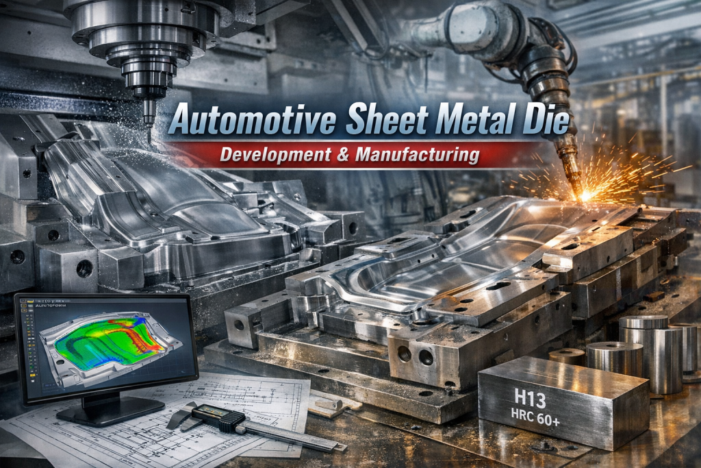
Introduction to Automotive Sheet Metal Dies
Sheet metal dies form the absolute backbone of modern vehicle production. They act as the primary equipment for creating auto body parts, directly dictating the quality, production takt rate, and overall cost of the final car.
In standard car manufacturing, roughly 70% of vehicle body components rely on sheet metal stamping. We group these components into three main categories: outer panels (doors, hoods, side outer panels), structural parts (crossbeams, longitudinal beams, pillars), and functional parts (dashboard brackets, seat rails).
To remain competitive, a high-quality stamping die must deliver on four core fronts: precision (ensuring dimensional consistency and assembly compatibility), lifespan (guaranteeing batch stability), efficiency (relating to production tempo), and low cost.
Why Sheet Metal Die Technology Matters Today
The push toward New Energy Vehicles (NEVs) requires lighter vehicle designs. This change brings difficult engineering hurdles, mostly due to the widespread use of high-strength steel and aluminum alloys. Their stamping characteristics differ vastly from traditional low-carbon steel.
Also, carmakers have compressed their traditional vehicle development cycles from 3 to 5 years down to just 1 to 2 years. Engineers must rely on standardized, highly efficient die design workflows. Breakthroughs in tooling technology are necessary to support the high-quality upgrade of the automotive manufacturing sector.
Full-Lifecycle Development Process & Engineering Planning
Developing automotive dies is a systematic engineering process. It demands tight integration across a full chain: Pre-planning → Design → Manufacturing → Assembly → Tryout → Acceptance → Mass Production Maintenance. Any deviation in a single link can lead to total tool scrap or sub-standard parts.
Stage 1: Pre-Planning and Requirement Analysis
Before drafting any designs, engineers map out the exact target specifications:
- Dimensional Tolerances: Exterior panels demand strict dimensional tolerances, usually within ±0.05 mm.
- Surface Quality: The stamped part must come out free of scratches, wrinkles, or cracks.
- Material Properties: The team must define whether they are working with DC04 low-carbon steel, DP600 high-strength steel, or 6061 aluminum alloy.
- Forming Processes: Determining if the part needs blanking, drawing, bending, or flanging.
Matching Die Type to Production Volume:
Expected production volume directly shapes the tooling strategy. For instance, a passenger car door inner panel with an annual capacity of 100,000 units needs a progressive die to handle continuous stamping at a rate of 15 parts per minute. Small-batch trial runs use single-operation dies, while compound dies handle multi-operation stamping efficiently.
Engineers also select the press tonnage, match stroke and worktable sizes, and calculate maximum drawing force to stop equipment from overloading.
Stage 2: Stamping Process Planning and Simulation Analysis
Good process planning sets up a successful tool. Engineers use Computer-Aided Engineering (CAE) software, like AutoForm and DYNAFORM, to run numerical simulations.
Take a complex side outer panel with deep curves as an example. Engineers use AutoForm to spot material sliding risks on the main character lines and step-face cracking in mating areas. By adjusting addendum surfaces and over-draw allowances on a computer screen, they fix defects virtually, reducing physical debugging cycles.
Process Routes & Nesting:
A simple bracket might only need a two-step “blanking + bending” route. A complex hood outer panel requires a five-step path: blanking → drawing → trimming → flanging → restriking. Also, optimizing nested layouts improves material utilization from an industry average of 65% to over 80%.
Stage 3: Die Design and Engineering Drawing Output
Die design converts process planning into physical structures, following clear rules: accuracy first, structural logic, and easy manufacturability/maintenance.
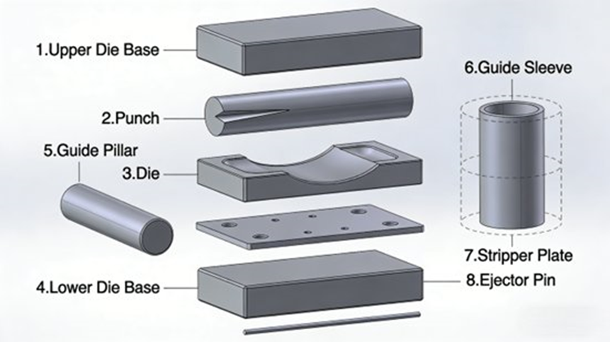
The engineering drawing output defines all core subsystems. This includes the overall structural layout (showing how all parts fit together), the punch and die components, guide mechanisms, stripping mechanisms (to pull scrap metal off the tool), and ejecting mechanisms (to push the formed part out). A proper overall structure diagram clearly shows the assembly relationship and fixation methods of these internal components to guide the manufacturing floor.
Core Design Technologies & Engineering Key Points
Core Technology 1: Punch and Die Design
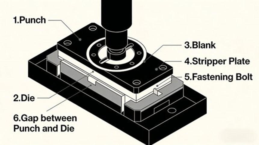
The punch and die do the heaviest work.
- Dimensional Accuracy: Tool tolerances need to be exactly 1/3 of the final part tolerance. If a part tolerance is ±0.06 mm, the tool tolerance stays within ±0.02 mm.
- Clearance Design: Clearance depends entirely on material thickness. Low-carbon steel uses 6%–8%, high-strength steel uses 10%–12%, and aluminum alloy needs 5%–7%.
- Engineering Example: A dual-gradient clearance compensation blade system used 0.038 mm clearance for a 0.75 mm sheet (front windshield upper crossbeam) and 0.028 mm clearance for a 0.55 mm sheet (hood inner panel). This kept all burrs strictly under 0.05 mm to meet the GB/T 33217-2016 standard.
- Structural Optimization: For drawing dies, punch radii should be > 5–8x the material thickness, and die radii > 3–5x the thickness. For bending dies (like bending 1.5 mm DC03 steel to 90°), using a punch radius of 3 mm and a die radius of 5 mm keeps springback under 0.5°.
- Material Selection: Cr12MoV serves best for blanking dies, while H13 (HRC 58-62) handles drawing dies.
Core Technology 2: Guide Mechanism Design
Guide post and guide bush systems keep everything aligned to prevent die offset.
- Precision Control: Fit accuracy hits H7/h6 standards. Straightness tolerance stays at ≤ 0.01 mm/m, and coaxiality at ≤ 0.005 mm. The guide post length must exceed the maximum closed height of the die.
- Structural Layout: Large outer panel dies need extra central guide units. A large side outer panel die uses 6 sets of guide pillars (4 at the corners, 2 in the middle) to stop deflection.
- Lubrication: Teams polish sliding surfaces to Ra ≤ 0.8 μm, apply high-temperature grease, and protect them with dust rings.
Core Technology 3: Forming Defect Prevention by Design
- Crack Prevention: Engineers increase punch and die corner radii. Example: A hood outer panel cracking problem disappeared after the team increased the die radius from 3 mm to 5 mm and raised the blank holder force from 80 kN to 120 kN.
- Wrinkle Prevention: Adding ring-shaped draw beads in door inner panel dies stabilizes material flow.
- Springback Control: Teams manage this through “over-bending” (reducing the punch angle by 1-2°) and 3D surface compensation using CATIA to keep windshield mating areas within tolerance.
- Scratch Prevention: Polishing working surfaces to Ra ≤ 0.4 μm, applying TiN coatings, and replacing hard alloy guide rollers with nylon-fiber contact assemblies stops scratches on exterior panels.
Key Manufacturing Processes, Assembly, and Tryout
Manufacturing strictly follows the design blueprints, controlling accuracy and surface quality.
Machining and Surface Treatment Flow
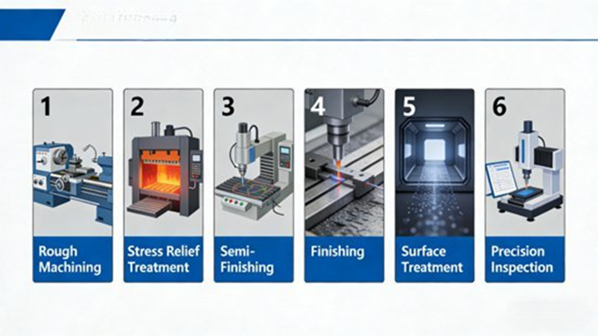
- Rough Machining: CNC milling removes raw material with a tolerance of ±0.1 mm and roughness of Ra ≤ 6.3 μm. Next comes stress relief aging (heating Cr12MoV at 200–250°C for 4–6 hours) to stop future distortion.
- Precision Machining: High-precision CNC centers reach finishing tolerances of ±0.005 mm. For massive complex surfaces, 5-axis CNC machining prevents repeated clamping errors, delivering accuracy of ±0.02 mm and roughness below Ra 0.8 μm. EDM handles complex curves with tolerances up to ±0.003 mm (Ra ≤ 0.4 μm), while Wire-Cut EDM (WEDM) cuts precise, sharp edges.
- Surface Treatment: Nitriding drives surface hardness up to HRC 65–70, boosting wear resistance by 3-5 times. TiN coatings cut down friction and extend drawing die life by more than 2 times. Chrome plating offers further corrosion resistance.
Heat Treatment Parameters for Die Steels
Proper heat treatment prevents quench cracking and edge chipping.
- H13 (Drawing Dies): Quench at 1050–1080°C (hold 2-3h, oil cool). Temper at 550–580°C (hold 4-6h, air cool). Final Hardness: HRC 58–62.
- Cr12MoV (Blanking Dies): Quench at 950–1000°C (hold 1.5-2h, oil cool). Temper at 200–250°C (hold 2-3h, air cool). Final Hardness: HRC 60–64.
Assembly, Tryout, and Mass Production Maintenance
During assembly, fit clearances are strictly monitored to avoid excessive gaps or jamming. Debugging (tryout) involves trial stamping and adjusting parameters to eliminate forming defects. Once debugging is complete, the die undergoes strict acceptance testing (verifying die accuracy, part quality, production takt, and lifespan).
Finally, the die moves into mass production maintenance, where strict upkeep strategies control lifecycle maintenance costs and ensure long-term batch stability.
Three-Level Quality Control System
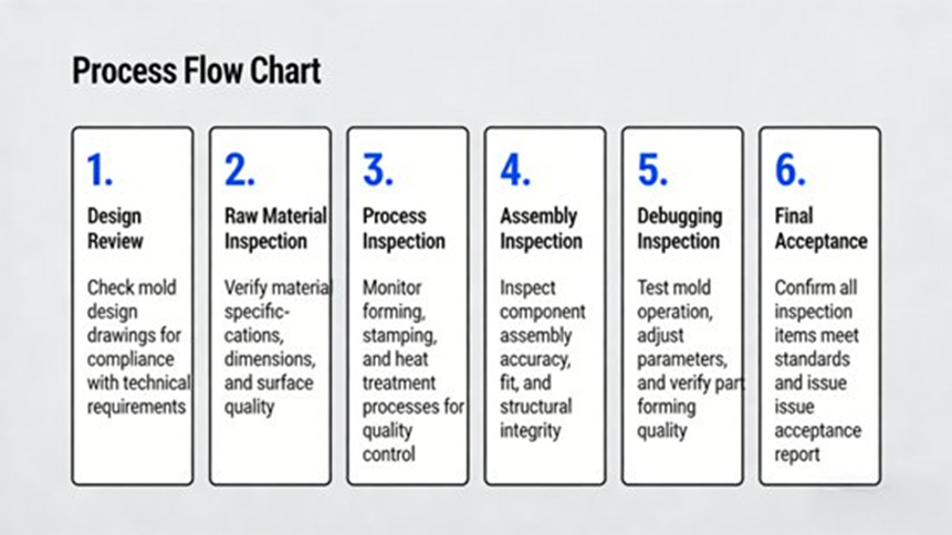
- Design Stage: Technical review boards verify dimensional accuracy, structural logic, and run 3D CAD visual interference checks.
- Manufacturing Stage: In-process checks follow every machining step using Coordinate Measuring Machines (CMM), projectors, and hardness testers. Strict raw material traceability tracks chemical composition and physical properties.
- Assembly & Tryout Stage: Workers use feeler gauges and dial indicators to check clearances. Tryout runs test the part against strict acceptance criteria.
Engineering Case Study: Passenger Vehicle Side Outer Panel Die
To see these rules in action, look at the development of a complex side outer panel die.
- Project Background: The part called for 1.2 mm DC04 low-carbon steel. Tolerances were tight at ±0.05 mm with zero surface defects allowed. The annual production target corresponded to 150,000 units, demanding a production speed of ≥ 12 parts/min and a die life of > 1 million strokes. The process covered drawing, trimming, flanging, and restriking.
- Challenge 1: Complex Curves & Springback. The team ran AutoForm simulations to redesign addendum surfaces. They changed the die radius from 3 mm to 5 mm, moved the punch radius from 5 mm to 8 mm, added ring draw beads, and set the blank holder force to 150 kN. Over-bending compensation held springback strictly under 0.3°.
- Challenge 2: Massive Die Size (2800 x 1500 x 800 mm). 5-axis CNC machining held accuracy at ±0.005 mm. A 6-set guide system created absolute stability, followed by post-machining stress relief aging.
- Challenge 3: Scratches & Lifespan. Workers polished surfaces to Ra ≤ 0.4 μm and applied a TiN coating. The H13 tool steel received heat treatment to reach HRC 58–62.
- Results: The debugging and tryout period dropped from 15 days to just 8 days. Production speed reached 14 parts/min, the dimensional pass rate hit 99.8%, and tool life passed 1.2 million strokes, heavily reducing maintenance costs and generating strong economic benefits.
Future Development Trends in Automotive Die Engineering
Die manufacturing is moving rapidly toward digital and intelligent integration. Facilities rely on CAD/CAM/CAE systems to achieve virtual design and virtual tryouts. Product Lifecycle Management (PLM) platforms and Digital Twin technology share real-time data to find potential manufacturing errors in virtual environments.
Lightweight die design is also growing. Using aluminum alloy mold steel cuts tool weight by >30% and drops energy consumption by 20%.
Finally, engineers are constantly upgrading tool steels to adapt to high-strength and composite materials. When combined with eco-friendly surface treatments and smart material nesting, green manufacturing becomes the sustainable baseline for the industry.
Frequently Asked Questions (FAQs)
1. Why do cracks occur during automotive sheet metal stamping, and how can they be prevented?
Short Answer: Cracks happen when the sheet metal stretches beyond its physical limit during forming, often due to tight tool radii or excessive holding force.
Details: This problem is common with high-strength steels and aluminum alloys because they have lower ductility than mild steel. Engineers solve this by increasing the punch and die fillet radii, adjusting the blank holder force (for example, raising it from 80kN to 120kN), and running simulation software like AutoForm to spot weak zones before cutting any steel.
2. How can springback be controlled in automotive stamping dies?
Short Answer: Engineers control springback by intentionally over-bending the metal or modifying the die surface so the material relaxes into the exact target shape.
Details: Springback is the natural elastic recovery of metal after the machine removes the forming load. Control strategies include “over-bending” (bending 1-2 degrees past the goal), 3D surface compensation via CAD/CAM (like CATIA), and optimizing holding pressure.
3. What are the most common defects in automotive sheet metal stamping?
Short Answer: The most frequent issues found on the production line are wrinkling, cracking, springback, burrs, and surface scratches.
Details: These problems usually stem from incorrect punch-die clearance, bad lubrication, or unstable material flow. Toolmakers prevent them by dialing in exact clearances, using draw beads to guide the metal, applying TiN coatings, and polishing die surfaces down to Ra ≤ 0.4 μm.
4. How should punch-die clearance be designed for different materials?
Short Answer: Clearance depends entirely on material thickness and type, ranging from 5% for soft aluminum up to 12% for rigid high-strength steel.
Details: Clearance dictates cut quality and tool wear. Recommended clearances relative to sheet thickness are:
- Low-carbon steel: 6–8%
- High-strength steel: 10–12%
- Aluminum alloy: 5–7%
5. How is digital simulation transforming automotive die development?
Short Answer: Simulation software lets engineers test and fix forming issues on a computer screen before manufacturing the physical die.
Details: Using CAD/CAM/CAE tools, engineers predict cracks and springback, automatically adjust die surfaces, and generate exact toolpaths for multi-axis CNC machines. This cuts down physical tryout iterations, speeds up development time, and lowers total production costs.
6. What does the full quality control workflow look like for automotive dies?
Short Answer: Quality control is a strict three-level system spanning design reviews, precision manufacturing checks, and final assembly tryouts.
Details: At the design level, engineers run 3D interference checks. During manufacturing, teams use CMMs, projectors, and hardness testers to verify tolerances (like ±0.005 mm) after every machining step, while ensuring raw material traceability. Finally, during assembly, feeler gauges check fit clearances before the die undergoes strict trial stamping to guarantee part quality and production takt rate.
