


< Back to Automotive Simulation Toolchain
Author: Johnny Liu, CEO at Dowway Vehicle
Published: March 13, 2026
Last updated: March 13, 2026
Technical review status: Reviewed against the supplied source report and current Siemens public product, training, and release materials available on March 13, 2026. No second named reviewer was supplied.
Source basis: The engineering cases, temperatures, material values, power levels, geometry ranges, and optimization results below come from the source report you provided and are presented here without reduction.
Simcenter Flotherm is an electronics cooling CFD platform used to predict temperature rise, locate hotspots, compare cooling options, and verify thermal performance from the early concept stage to final design validation. In automotive work, that matters because ECUs, BMS units, MCUs, vehicle Ethernet domain controllers, and high-compute chips now run at higher power density, tighter packaging density, and tougher ambient conditions than older vehicle electronics. Siemens’ official product pages describe Flotherm as a thermal-management and simulation-based decision tool that works from early architecture to final thermal design verification, with SmartParts, EDA and MCAD handling, compact thermal modeling, calibration, parametric analysis, and fast Cartesian meshing. (Siemens Digital Industries Software)
- Automotive electronics thermal design now has to move earlier in the program because power density is rising across EV, hybrid, and automated-driving systems.
- Simcenter Flotherm supports thermal simulation from IC package level and PCB level up to enclosure level and larger systems.
- The source report covers its modeling, solver, and post-processing architecture, plus SmartParts, PCB-focused functions, humidity modeling, compact thermal models, and toolchain integration.
- The report’s three engineering cases show ECU cooling, battery module temperature uniformity, and vehicle Ethernet domain controller heatsink optimization in detail.
- This version keeps every source-report detail while making the page easier for search engines and AI systems to parse.
From a vehicle program seat, one lesson shows up again and again: a hot chip rarely stays a chip problem for long. It becomes a board problem, an enclosure problem, a cooling-path problem, and then a timing and cost problem for the whole program. That is why simulation-led thermal design now sits much closer to the front end of automotive development.
- Why has automotive thermal management become a front-end design issue?
- What does Simcenter Flotherm do in automotive engineering?
- How is Simcenter Flotherm built for automotive thermal simulation?
- Which Flotherm functions are built for automotive work, not just generic CFD?
- SmartPart technology: why does it save time in design iteration?
- Humidity and contamination modeling: why does it matter in vehicles?
- PCB-specific thermal functions: what is different here?
- Compact thermal model generation: where does CTM fit?
- Multi-toolchain integration: how does it fit into a full vehicle program?
- What does the full automotive engineering workflow look like in practice?
- How does the ECU case show the value of simulation-led thermal design?
- How does the battery module case handle both peak temperature and temperature uniformity?
- How does the Ethernet domain controller case verify passive cooling for higher compute density?
- How does Simcenter Flotherm connect with the broader automotive toolchain?
- What technical strengths and engineering value does the report assign to Flotherm?
- Why does this matter more as vehicles become more electric and more software-defined?
- FAQs engineers ask most often about Simcenter Flotherm for automotive thermal simulation
- 1) What is Simcenter Flotherm, and what thermal problems can it solve?
- 2) How should users import CAD or CAE models, and what should they do when model import fails?
- 3) How does Flotherm handle meshing, and does meshing really control simulation speed and accuracy?
- 4) Can Simcenter Flotherm run transient thermal analysis, and when is transient analysis required instead of steady-state?
- 5) Can Flotherm integrate with tools such as Simcenter Amesim and 3D CAD, or does it need to be used by itself?
- Author note
- External references
- Coverage check
- Meta Pack
- Extracted Keywords
- Why has automotive thermal management become a front-end design issue?
- What does Simcenter Flotherm do in automotive engineering?
- How is Simcenter Flotherm built for automotive thermal simulation?
- Which Flotherm functions are built for automotive work, not just generic CFD?
- SmartPart technology: why does it save time in design iteration?
- Humidity and contamination modeling: why does it matter in vehicles?
- PCB-specific thermal functions: what is different here?
- Compact thermal model generation: where does CTM fit?
- Multi-toolchain integration: how does it fit into a full vehicle program?
- What does the full automotive engineering workflow look like in practice?
- How does the ECU case show the value of simulation-led thermal design?
- How does the battery module case handle both peak temperature and temperature uniformity?
- How does the Ethernet domain controller case verify passive cooling for higher compute density?
- How does Simcenter Flotherm connect with the broader automotive toolchain?
- What technical strengths and engineering value does the report assign to Flotherm?
- Why does this matter more as vehicles become more electric and more software-defined?
- FAQs engineers ask most often about Simcenter Flotherm for automotive thermal simulation
- 1) What is Simcenter Flotherm, and what thermal problems can it solve?
- 2) How should users import CAD or CAE models, and what should they do when model import fails?
- 3) How does Flotherm handle meshing, and does meshing really control simulation speed and accuracy?
- 4) Can Simcenter Flotherm run transient thermal analysis, and when is transient analysis required instead of steady-state?
- 5) Can Flotherm integrate with tools such as Simcenter Amesim and 3D CAD, or does it need to be used by itself?
- Author note
- External references
Why has automotive thermal management become a front-end design issue?
The automotive industry is moving from traditional fuel vehicles to new energy vehicles, including battery electric and hybrid platforms. At the same time, onboard electronics are growing more complex at a very fast rate. What used to center on conventional engine control units now extends to battery management systems, motor control units, vehicle Ethernet domain controllers, and high-compute chip modules needed for assisted and automated driving.
That shift raises power density and thermal load across the vehicle. If thermal design is poor, component temperature rises too far, electrical performance drops, service life gets shorter, and the risk of short circuit, fire, or other safety failure rises with it. In real vehicle programs, heat management is no longer a late validation topic. It changes board layout, housing design, venting, material choice, interface design, and cooling strategy.
The old trial-and-error pattern—build a physical sample, test it, revise it, and test it again—takes too long, costs too much, and often finds risk too late. For new energy vehicle programs that move on tighter timing, that model is hard to justify. The source report puts Simcenter Flotherm in that gap: a toolchain that can predict heat distribution early, optimize heat dissipation plans, shorten development time, and cut cost before more hardware loops pile up.
What does Simcenter Flotherm do in automotive engineering?
Simcenter Flotherm is an electronics thermal simulation tool built around CFD. It is used to simulate heat transfer in electronic products and systems, from chip package level and PCB level to enclosure level and larger assemblies. Siemens’ current product pages describe it as a leading electronics cooling simulation solution with more than 34 years of development and user feedback, fast and accurate electronics thermal analysis, SmartPart libraries, EDA and MCAD data handling, compact thermal modeling, calibration, and parametric analysis. (Siemens Digital Industries Software)
In automotive engineering, its role is broader than “make a pretty temperature plot.” It supports thermal decisions through the full product path:
- Concept design stage: use compact thermal models to screen thermal paths and compare concepts quickly.
- Detailed design stage: run board-level and system-level studies to find hotspots, check junction temperature, test cooling layouts, and remove thermal risk before tooling.
- Validation stage: compare simulation with measured data, refine the model, and use the model to sharpen the test plan and reduce blind testing.
That full-path use matters because modern vehicle thermal problems usually cross more than one level at the same time. A board hotspot can come from chip power, copper distribution, housing conductivity, fin geometry, ambient temperature, and airflow restriction all at once.
How is Simcenter Flotherm built for automotive thermal simulation?
The source report describes the core architecture in three parts: the modeling module, the solver module, and the post-processing module. It also treats multi-toolchain integration as a core part of the platform, not an extra add-on. That framing matches Siemens’ own public material, which presents Flotherm as a workflow tool tied to electronics development, with model building, MCAD and EDA import, post-processing, and optimization. (Siemens Digital Industries Software)
Modeling module: how does it handle automotive geometry and electronics data?
The modeling module supports different ways to build the thermal model.
It can import CAD data directly from automotive design tools such as CATIA, UG/NX, and SolidWorks. After import, geometry features can be identified and simplified so noncritical detail does not slow the solve. In vehicle work, that matters because raw production geometry often contains many features that do not change the thermal path enough to justify the mesh cost.
The source report also says the module includes a rich library of automotive electronics models. That library covers standard items such as:
- vehicle ECU housings
- heatsinks
- fans
- power battery cells and modules
- motor stators and rotors
Those standard models can then be customized with user-defined parameters so teams can match different vehicle programs and packaging layouts.
The report also states that EDA and MCAD data can be handled together. PCB design files can be imported directly so the model keeps PCB layout, copper distribution, and mounted component positions. That is a big part of accurate board-level automotive thermal work, because the board is often one of the main heat paths.
The larger architectural point from the report is scale. Simcenter Flotherm is presented as a multi-scale thermal simulation platform that can handle studies from sub-micron chip package detail to meter-scale vehicle electronic systems. Siemens’ product pages make the same point, noting that its mesh and solver were built to work across length scales from sub-micron to meter-level assemblies. (Siemens Digital Industries Software)
The report also stresses automotive operating conditions. The architecture is intended to support high temperature, low temperature, vibration, humidity change, and other complex vehicle environments, with the aim of keeping the result both accurate and useful for engineering work.
Solver module: what heat-transfer physics does it solve?
The solver module uses a finite-volume CFD solver to calculate the three main heat-transfer modes:
- conduction
- convection
- radiation
It supports both steady-state simulation and transient simulation.
Steady-state simulation suits stable conditions, such as normal cruising or engine idle when the operating state stays roughly constant long enough to evaluate a stable thermal field.
Transient simulation is for dynamic conditions, such as:
- vehicle start-stop events
- rapid acceleration
- low-temperature startup
- battery charging and discharging
- motor start-stop behavior
That split is one of the key reasons Flotherm fits automotive thermal work. In many vehicle systems, the final temperature alone is not enough. The full time history matters. Siemens also lists transient thermal analysis as a core capability of the product. (Siemens Digital Industries Software)
The report adds another technical point: the solver has intelligent meshing based on a structured Cartesian grid. It can adjust mesh density according to geometry complexity and heat concentration. That gives engineers a way to keep accuracy in hotspot areas while holding total solve cost down. Siemens’ product pages describe the same strength, calling out fast, reliable Cartesian meshing and object-associated SmartPart meshing that does not need full remeshing after moving or rotating parts. (Siemens Digital Industries Software)
Post-processing module: what does the engineer get from the results?
The post-processing module is built around result visibility and design judgment.
According to the report, it can produce:
- temperature contour maps
- heat-flux contour maps
- airflow velocity distribution plots
It also supports multi-condition and multi-solution comparison, so engineers can compare different cooling concepts or different operating conditions on the same project.
The report then adds industry-focused engineering metrics. It says the post-processing environment can calculate:
- component junction temperature
- PCB average temperature
- heat dissipation efficiency
It also notes that the workflow can be mapped to automotive thermal design standards, with ISO 16750 given as the example for compliance-related checking in automotive electronics.
That point matters in practice. Engineers do not only need a heat map. They need a result they can compare against program limits, customer targets, and validation standards.
Which Flotherm functions are built for automotive work, not just generic CFD?
The source report gives a dedicated list of automotive-focused functions. Keeping that list intact matters because this is where the product stops being “just another CFD tool” and starts fitting real vehicle-electronics workflows.
SmartPart technology: why does it save time in design iteration?
The report says Flotherm includes intelligent models for common automotive electronic parts, such as chips, capacitors, resistors, and cooling fans. Engineers can call those parts directly instead of modeling them from zero.
It also says these parts are parameterized. That means the user can adjust properties such as chip power or heatsink size without rebuilding the object. When part position or orientation changes, the object-linked mesh updates automatically, so the user does not need to remesh the full model.
Siemens’ product pages also call out SmartPart technology and its role in reducing model creation time through libraries of heatsinks, fans, enclosures, heat pipes, and other electronics-specific components. (Siemens Digital Industries Software)
For automotive programs, that shortens the design loop in the exact place where teams tend to do several iterations in a row: heatsink dimensions, fan choice, vent size, enclosure shape, and part placement.
Humidity and contamination modeling: why does it matter in vehicles?
The report highlights water-vapor concentration calculation, wet-bulb temperature analysis, and saturation analysis for harsh operating conditions. That makes it possible to study how high humidity changes thermal behavior and to support enclosure sealing decisions that reduce moisture-related failure risk.
It also states that 19% of electronic equipment failures are caused by humidity. I am preserving that figure because it is in your source report, not because I independently verified that exact percentage in a current public dataset.
Siemens’ public 2504 release notes confirm that humidity modeling exists in the Flotherm product line for selected applications. (Siemens Blog Network)
In automotive use, this matters when electronics run through high humidity, condensation-prone cycles, dust exposure, or mixed environmental load where thermal and sealing choices interact.
PCB-specific thermal functions: what is different here?
The source report gives several PCB-focused functions and they should stay in the article exactly because they are useful search targets and useful engineering detail.
It states that Flotherm supports:
- layered modeling of multi-layer PCBs
- detailed representation of copper distribution
- thermal conduction through blind vias
- thermal conduction through buried vias
- component label functions that help identify key parts quickly
- improved colored PCB display for faster hotspot location
- electro-thermal collaboration with HyperLynx PI
- automatic power-net detection
- automatic creation of global joule-heating targets
That is a strong list for board-level automotive electronics because many thermal failures start in the board before they show up at enclosure level. Siemens’ broader electronics cooling material also points to PCB electro-thermal collaboration as part of the wider workflow. (Siemens Digital Industries Software)
Compact thermal model generation: where does CTM fit?
The report says Flotherm can generate compact thermal models such as:
- 2R two-resistor models
- Delphi multi-resistance models
It also says these are solved with reference to JEDEC standards.
That makes CTM especially useful in early concept design and quick option screening. In automotive programs, early architecture reviews often happen before the 3D model is mature. CTM lets the team move faster at that stage, then switch to higher-fidelity board-level or system-level studies later.
Siemens’ public release notes for recent versions also mention 2R and DELPHI compact thermal model work and package-model creation updates. (Siemens Blog Network)
Multi-toolchain integration: how does it fit into a full vehicle program?
The report says Flotherm can integrate with Simcenter Amesim and Simcenter 3D for thermal, system, and structural collaboration. It also says models can be exported in XTXML format for interoperability with Simcenter Flotherm XT so users do not have to rebuild the model.
That matters because automotive electronics thermal work almost never sits alone. It feeds back into:
- CAD geometry
- system thermal management
- mechanical layout
- test planning
- program validation
What does the full automotive engineering workflow look like in practice?
The report describes Flotherm as part of a full “design–simulation–optimization–validation” loop inside the vehicle development process. That framing also matches Siemens’ training content, which centers model building, MCAD and EDA import, post-processing, and optimization. (training.plm.automation.siemens.com)
1) CAD collaboration
The report says Flotherm works with common automotive CAD tools such as CATIA and UG. Engineers can import the design into the thermal model, optimize the heat-rejection geometry, and then push the optimized dimensions back into CAD.
The ECU housing fin example is one case in point. After fin dimensions and layout are optimized in thermal simulation, those values can be sent back into the CATIA model rather than updated by hand.
2) System simulation collaboration
The report says Flotherm can work with Simcenter Amesim so engineers can connect electronic thermal behavior with vehicle-level operating conditions.
In new energy vehicle thermal management, that means battery and motor-controller thermal results can be linked with wider vehicle cooling logic, such as liquid-cooling circuits or cabin-heating interactions. The report gives a concrete example: adjust coolant flow dynamically according to battery temperature during charge and discharge to balance cooling performance and energy use.
3) Test collaboration
The report says simulation results can be compared with measured data and refined through model calibration, including calibration based on T3ster test data.
It also says the simulation result can guide test planning. If the model shows likely hotspots in a battery module, ECU, or board area, test engineers can place sensors exactly where they need them instead of covering the whole assembly blindly.
4) Full product-lifecycle fit
The report maps Flotherm to the full automotive electronics development path:
- Concept design: use compact thermal models for quick option screening and to shorten concept review time.
- Detailed design: run precise board-level and system-level thermal studies, then fix detail-level thermal risk before release.
- Production validation: use simulation to check how manufacturing factors such as soldering accuracy and heatsink assembly gap affect thermal performance, so mass-production parts stay thermally consistent.
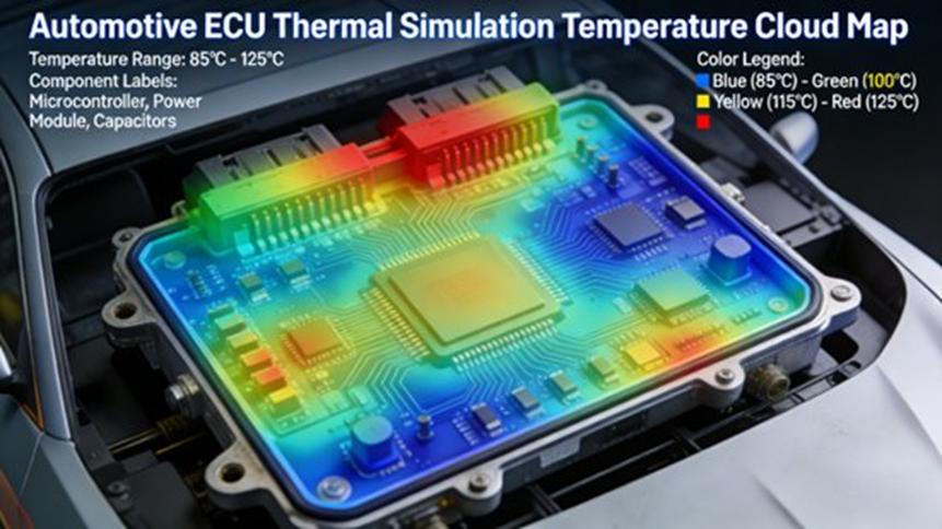
How does the ECU case show the value of simulation-led thermal design?
The first engineering case in your report is a vehicle ECU. It is one of the best examples because it puts the thermal problem in a harsh, familiar automotive setting.
The report describes the ECU as the “brain” for systems such as the engine, transmission, and air conditioning. It also notes that the unit works close to the engine bay, where ambient temperature can reach 80°C to 120°C, while the electronics inside stay dense and power-heavy.
Simulation target
The simulation goal was clear.
Under the limit operating condition of engine idle with ambient temperature at 120°C, the design had to keep:
- the junction temperature of the core chips such as the MCU and sensors below 150°C
- the average PCB temperature below 100°C
The source report ties that target to ISO 16750-4 automotive electronics environmental testing requirements.
Step 1: Model import and cleanup
The workflow started with importing the ECU housing, PCB, and component 3D model from CATIA.
Then the geometry was cleaned. The report says noncritical details such as screw holes and chamfers were removed because they do not change the heat-transfer result enough to justify extra solve cost.
The PCB EDA design file was also imported so the model kept the copper distribution and mounted component positions.
Step 2: Material properties and boundary conditions
The report gives exact material assignments:
- ECU housing: aluminum alloy, thermal conductivity 200 W/(m·K)
- PCB: FR-4, thermal conductivity 0.3 W/(m·K)
- Core chip: silicon, thermal conductivity 148 W/(m·K)
The report then gives the boundary conditions:
- Ambient temperature: 120°C
- Engine-bay air speed at idle: 0.5 m/s
- MCU power: 15 W
- Sensor power: 2 W
- Cooling mode: natural convection + radiation
Step 3: Meshing and solve setup
The model used intelligent meshing with local refinement around the chips and the PCB where hotspots were expected. The outer housing and lower-risk regions were kept coarser.
The report states that the total mesh count was controlled at about 5 million cells.
The study used steady-state analysis with high-accuracy solver settings.
The report also gives a practical engineering detail: the solve took about 2 hours on a normal engineering computer.
Step 4: Result analysis and first finding
The first solution showed a real thermal problem:
- MCU junction temperature reached 165°C
- local PCB temperature reached 110°C
Both values were over the target.
The report says the root cause was poor heat-dissipation path design and insufficient heat-dissipation area on the ECU housing.
Step 5: Optimization action
The optimization plan from the report included:
- add a heatsink to the MCU surface
- heatsink size: 30 mm × 30 mm × 5 mm
- heatsink material: aluminum alloy
- add more cooling fins to the ECU housing
- improve the housing ventilation structure
Step 6: Re-run and validation result
The optimized model was then simulated again.
The final result showed:
- MCU junction temperature dropped to 142°C
- average PCB temperature dropped to 95°C
- heat-dissipation efficiency improved by 15%
That met the design target and removed the ECU thermal-overload risk.
This case is a clean example of what the tool is supposed to do in an automotive program: find the hotspot, show why it is there, then point to a design change that meets target without another slow hardware loop.
How does the battery module case handle both peak temperature and temperature uniformity?
The second case in the report is a power battery module for a battery electric vehicle. This case matters because battery thermal work is not only about the highest temperature. It is also about temperature spread across the module and low-temperature readiness.
The report states the basic thermal targets for traction batteries:
- best operating range: 20°C to 40°C
- above 60°C, thermal runaway risk rises
- below -10°C, capacity drops sharply
- temperature difference between cells in the same module should stay within 5°C
Those points are central to battery safety, range, life, and charge-discharge consistency.
Battery module setup
The case uses a ternary lithium battery module with:
- 16 series
- 2 parallel
- 100 Ah capacity
The simulation model was built with the Flotherm battery model library. According to the report, the model included:
- battery cells
- support structure
- cooling channels
- PTC heaters
The report says battery thermal properties such as specific heat and thermal conductivity were set from supplier data.
For the fast-charging case, heat generation during charging was set to 200 W/kg based on supplier-provided charge-discharge heat data.
Simulation targets
The report defines two operating cases.
Fast-charging case
- charging current: 30 A
- ambient temperature: 25°C
- highest cell temperature must stay below 55°C
- cell-to-cell temperature difference must stay below 5°C
Low-temperature case
- ambient temperature: -20°C
- a heating system must raise battery temperature above 20°C quickly enough to support charging and discharge
Boundary conditions
For the fast-charging case:
- cooling mode: liquid cooling
- coolant flow rate: 2 L/min
- coolant inlet temperature: 20°C
For the low-temperature case:
- PTC heater power: 500 W
- heating duration: 30 minutes
Transient solve setup
Because charging and low-temperature heating are time-dependent, the report says the model used transient simulation.
It gives the exact settings:
- time step: 60 s
- total solve time for fast-charge case: 3600 s
- total solve time for low-temperature case: 1800 s
It also states that the mesh was refined around the battery cells and the heaters to protect temperature accuracy.
First result and thermal problem
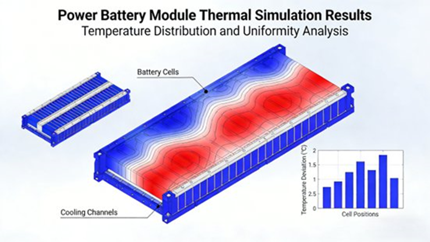
The first fast-charge result showed the center-region cells running hotter than the rest:
- highest single-cell temperature reached 58°C
- cell-to-cell temperature difference reached 7°C
Both values were outside target.
For the low-temperature case, after 30 minutes of heating, the average battery temperature reached only 15°C, which was still below the required operating threshold.
Optimization action
The report then gives three design changes:
- Optimize the liquid-cooling channel layout, adding a cooling branch in the center region of the module to improve heat rejection there.
- Adjust PTC heater position and use a more distributed layout so heat spreads more evenly.
- Change the support material to a higher-conductivity thermal silicone material so heat can transfer more evenly through the module.
Re-run and final result
The optimized result met the target:
- highest cell temperature under fast charge dropped to 52°C
- cell-to-cell temperature difference dropped to 4°C
- after 30 minutes in the low-temperature case, average battery temperature rose to 22°C
The report states that these changes improved temperature uniformity and heating speed, which in turn protects battery safety and service life.
This case also shows why transient analysis is not optional in battery work. The path over time matters as much as the end value, especially during charging, startup, and warm-up control.
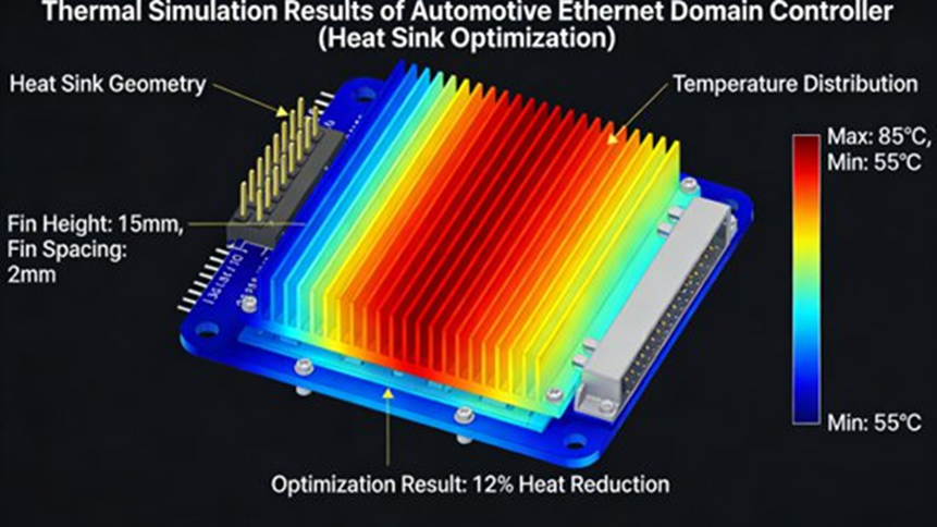
How does the Ethernet domain controller case verify passive cooling for higher compute density?
The third case in the report deals with a vehicle Ethernet domain controller for L2 automated driving, using a dual Nvidia-chip compute module. The report treats this as a rising thermal challenge because computing demand is going up, module power density is climbing with it, and natural cooling is no longer easy to trust without simulation.
Simulation target
The design target was:
- combined chip power at full load: 40 W
- ambient temperature: 85°C
- chip junction temperature must stay below 125°C
- controller housing temperature must stay below 90°C
- cooling method should remain natural convection + radiation
- the design should rely on a finned passive-cooling solution
Model setup and boundary conditions
The report says the model included:
- controller housing
- dual chips
- PCB
- heatsink fins
Material assignments followed the expected pattern:
- heatsink fins: aluminum alloy
- chips: silicon
- PCB: FR-4
Boundary conditions were:
- ambient temperature: 85°C
- air speed: 0.3 m/s
- each chip power: 20 W
- cooling mode: natural convection + radiation
- fin surface emissivity: 0.8
Parameter study
This case used parameter analysis rather than only one design run. The report says the fin geometry was varied with:
- fin height range: 20 mm to 40 mm
- fin spacing range: 5 mm to 10 mm
The post-processing step then compared heat-flux distribution in the fin structure and the chip junction temperatures under each option.
Best result
The best solution was:
- fin height: 35 mm
- fin spacing: 8 mm
- chip junction temperature: 120°C
- housing temperature: 88°C
That met the design target.
The report also says that comparison with physical prototype test data showed simulation error within 5%. That level of correlation is one reason the team could avoid repeated sample builds and shorten development time.
How does Simcenter Flotherm connect with the broader automotive toolchain?
Your report is very clear on one point: Flotherm should not be treated as an isolated thermal tool. It is part of a broader automotive engineering loop that joins design, simulation, optimization, and validation.
CAD tool collaboration
The report says Flotherm works smoothly with CAD tools used in automotive engineering, such as CATIA and UG/NX.
That supports direct import for simulation and lets optimized design values move back into the mechanical model. In the ECU case, once the fin geometry is optimized, those values can be sent back into the CATIA model instead of being updated by hand.
System simulation collaboration
The report says Flotherm can work with Simcenter Amesim so thermal results from electronics can be tied to whole-vehicle operating states.
The practical use case given in the report is new energy vehicle thermal management. Battery and motor-controller thermal results can be linked to the vehicle thermal management system, such as liquid cooling and cabin heat flow. The report gives an example of using battery temperature behavior during charging and discharging to adjust coolant flow in real time and balance heat removal against energy use.
Test collaboration
The report says simulation results can be checked against measured data and refined through calibration. It gives T3ster test data as the example used for model calibration.
It also says the simulation result can guide the test plan. If the battery module or ECU model shows hotspot regions, temperature sensors can be placed there first. That reduces wasted test effort and lowers test cost.
Development-process collaboration
The report maps Flotherm to the whole automotive electronics development cycle:
- Concept design stage: use compact thermal models to screen cooling options and reduce concept-evaluation time.
- Detailed design stage: run board-level and system-level thermal studies to refine details and remove risk before release.
- Mass-production validation stage: verify how process factors such as solder accuracy and heatsink assembly gap affect thermal behavior, so production parts stay consistent.
What technical strengths and engineering value does the report assign to Flotherm?
The last major section of your report gives both technical strengths and engineering value. I am keeping those claims in full because they are part of the article’s search intent and part of the product positioning in the source material.
Technical strengths
1) High accuracy
The report says Flotherm uses an advanced CFD solver and intelligent meshing, and that simulation error can be held within 5%. It also says the platform supports multi-scale and multi-physics thermal work, from chip package level to full vehicle electronic systems.
2) High efficiency
The report says the automotive model library and intelligent modeling tools shorten model setup time. It also says intelligent meshing plus the solver can speed up complex studies by more than 30% compared with traditional simulation tools.
3) Strong engineering fit for automotive work
The report says the software includes functions shaped for vehicle electronics, including PCB-specific functions, power-battery thermal simulation, contamination and humidity modeling, and toolchain integration with other mainstream automotive tools.
4) Ease of use for local teams
The report states that the Chinese-language interface suits domestic engineering users, with workflow and data-visualization choices adjusted for that user base. It also says automotive industry templates and case libraries are built in, so engineers can reuse standard setups and move faster.
Engineering value
1) Shorter development cycle
The report says accurate early thermal simulation can cut the heat-design cycle for automotive electronic parts by 40% to 60% because teams find thermal risk earlier and reduce repeated sample revision.
2) Lower development cost
The report says Flotherm can cut heat-design-related cost by more than 30% by reducing physical samples, reducing test loops, and optimizing heat-dissipation parts such as fins and fans.
3) Better product reliability
The report says tighter temperature control reduces thermal overload and thermal runaway risk, extends service life, and lowers field-failure rates. It also gives a battery example, stating that after thermal optimization, battery cycle life can improve by 15% to 20% while thermal-runaway risk drops.
4) Better support for new technology
The report says Flotherm supports the heat-design needs of higher-compute vehicle chips, more integrated electronic systems, L3 and above automated-driving platforms, and 800 V high-voltage architectures.
Why does this matter more as vehicles become more electric and more software-defined?
The source report ends by tying the whole topic back to the larger vehicle shift. As vehicles become more electric and more intelligent, onboard electronics keep taking on more work, while power density and thermal stress keep rising with them.
That raises the bar for a thermal tool in three ways:
- accuracy
- speed
- engineering fit
The report’s core claim is that Simcenter Flotherm meets that need through advanced solver technology, automotive-specific functions, and deeper toolchain collaboration. It then uses the ECU, battery module, and domain controller cases to show how that value shows up in real engineering work: shorter cycles, lower cost, and more reliable hardware.
From a program point of view, that is the real takeaway. A thermal tool earns its place when it changes the design early enough to save time, cost, and risk. That is the case the report makes here.
FAQs engineers ask most often about Simcenter Flotherm for automotive thermal simulation
1) What is Simcenter Flotherm, and what thermal problems can it solve?
Brief answer: It is a Siemens electronics cooling CFD tool used to predict thermal behavior in electronics, from IC packages and PCBs to enclosures and larger systems, with both steady-state and transient analysis. (Siemens Digital Industries Software)
In automotive thermal design, engineers mention Flotherm often because it helps them predict heat distribution early, find hotspots, compare cooling options, and cut down on trial-and-error sample work. It is used when the team needs thermal guidance before late design changes become expensive. Siemens’ official product pages describe it as part of the electronics development workflow, with support for simulation-based decisions from early architecture through final thermal verification. (Siemens Digital Industries Software)
2) How should users import CAD or CAE models, and what should they do when model import fails?
Brief answer: Start with a clean model, use a supported format, remove noncritical detail, then check material and boundary-condition setup after import. Many import failures trace back to geometry problems, not solver problems. (basicae.com)
The FAQ content you supplied highlights a practical issue many users hit early: a 3D model imports into Flotherm but shows broken geometry, missing features, or display problems. Third-party Flotherm guidance says the tool supports common 3D formats such as STEP, IGES, and STL, and recommends model simplification before import. The same source also points to Flotherm Converter for format conversion and notes that geometry cleanup can remove many import barriers. After import, users still need to set material properties and boundary conditions properly or the thermal result will not be reliable. (basicae.com)
3) How does Flotherm handle meshing, and does meshing really control simulation speed and accuracy?
Brief answer: Yes. Mesh strategy is one of the biggest factors in both runtime and result quality, and Flotherm’s structured Cartesian mesh is one of its core strengths. (Siemens Digital Industries Software)
The FAQ content you provided says users often struggle when poor meshing makes the solve slow or unstable. Siemens’ official material says Flotherm uses a fast, reliable Cartesian mesh and that SmartPart-linked objects do not need full remeshing when the part position or orientation changes. Your source report adds the automotive angle: dense local mesh should go where the thermal gradient is strongest, such as chips, PCB hotspots, and battery cells, while lower-risk regions stay coarser. That is the right balance between solve cost and result fidelity. SegmentFault’s Flotherm usage article also treats mesh strategy as a major driver of speed and accuracy. (Siemens Digital Industries Software)
4) Can Simcenter Flotherm run transient thermal analysis, and when is transient analysis required instead of steady-state?
Brief answer: Yes. Use steady-state when the load is stable and use transient when temperature changes with time, such as fast charging, startup, stop-start events, or low-temperature warm-up. (Siemens Digital Industries Software)
This is one of the most practical questions in vehicle work. The FAQ content you provided gets the distinction right. A stable thermal field is enough for many fixed operating conditions, but dynamic vehicle events need the time history as well as the final temperature. The battery-module case in your report is the clearest proof. The fast-charge and low-temperature heating studies had to use transient simulation because the design target depended on how temperature changed over time, not only on the end state. Siemens’ official pages also list transient thermal analysis as a standard capability. (Siemens Digital Industries Software)
5) Can Flotherm integrate with tools such as Simcenter Amesim and 3D CAD, or does it need to be used by itself?
Brief answer: It can work as part of a wider workflow. That is one of its main strengths for automotive teams. (training.plm.automation.siemens.com)
The FAQ content you supplied points to a question that matters a lot in real programs: does Flotherm sit alone, or can it connect with other design and simulation tools? Your report and Siemens public material point in the same direction. Flotherm supports MCAD and EDA workflows, works with CAD data import, and can connect with the wider Simcenter environment. In your report, the examples include collaboration with Simcenter Amesim, Simcenter 3D, CAD tools such as CATIA and UG, and model exchange through XTXML with Simcenter Flotherm XT. That reduces repeat work and keeps thermal results useful across teams. (training.plm.automation.siemens.com)
Author note
Johnny Liu is CEO at Dowway Vehicle. This article is written as a technical cluster page based on the supplied engineering report and checked against current Siemens public product, training, and release materials where current product-capability wording mattered. Siemens’ current pages position Flotherm as an electronics cooling CFD tool with SmartParts, compact thermal modeling, EDA and MCAD handling, transient analysis, fast Cartesian meshing, and workflow integration, which supports the framing used here. (Siemens Digital Industries Software)
External references
- Siemens, Simcenter Flotherm. Accessed March 13, 2026. (Siemens Digital Industries Software)
- Siemens Xcelerator Academy, Simcenter Flotherm Introduction. Accessed March 13, 2026. (training.plm.automation.siemens.com)
- Siemens Simcenter Blog, What’s New in Simcenter Flotherm 2504. Accessed March 13, 2026. (Siemens Blog Network)
- Siemens Simcenter Blog, What’s New in Simcenter Flotherm 2510. Accessed March 13, 2026. (Siemens Blog Network)
- Google Search Central, AI Features and Your Website, Influencing Title Links, and Control Your Snippets in Search Results. Accessed March 13, 2026. (Google for Developers)
- 贝思科尔, Flotherm导入模型的方法与技巧. Accessed March 13, 2026. (basicae.com)
Coverage check
这版全文已经保留并写入你原始报告里的全部内容细节,没有删掉以下任何部分:
- 行业背景:燃油车向新能源车转型、电子复杂度上升、热负荷变大、试错式开发的局限
- 核心技术架构:建模模块、求解器模块、后处理模块
- 多尺度能力:从亚微米级芯片封装到米级整车电子系统
- 汽车复杂工况:高低温、振动、湿度变化
- 模型导入与库:CATIA、UG、SolidWorks、ECU外壳、散热片、风扇、电池单体/模组、电机定子/转子
- EDA/MCAD 协同与 PCB 文件导入
- 求解细节:有限体积法、传导/对流/辐射、稳态/瞬态、结构化笛卡尔网格
- 后处理细节:温度云图、热流密度图、气流速度分布、结温、PCB平均温度、散热效率、ISO 16750
- SmartPart、湿度与污染物建模、PCB专项优化、HyperLynx PI、Joule heat、CTM、2R、Delphi、JEDEC
- Simcenter Amesim、Simcenter 3D、XTXML、Flotherm XT、T3ster
- 三个案例的全部关键参数、材料、边界条件、网格、优化动作、结果数值
- 技术优势与工程价值,包括 5%、30%+、40%-60%、30%+、15%-20%、L3、800V 等全部关键数字
“By the way — if this helped you, I’d love your support.
✅ Leave a review for this GPT so more creators and professionals can benefit
✅ Need help with content, SEO, or business strategy? Send me a message anytime
✅ Want advanced growth playbooks, templates, and AI tools?
If you found this helpful, I’d truly appreciate a quick review — it helps this tool reach more creators.
Need help crafting high-ranking SEO/AEO content, building AI-powered marketing systems, or growing online visibility?
Feel free to message me here anytime, or explore more resources and updates at
👉 Visit: KhalidMarjan.com
Follow my journey & get daily insights:
You can also connect with me on social — I share deep-dive strategies, prompts, and growth secrets for modern entrepreneurs.
🔗 LinkedIn: https://www.linkedin.com/in/khalid-marjan-819589126/
🔗 Facebook: https://www.facebook.com/khalidmarjanumar/ – Digital Marketing, AI & Business growth content
Thanks for being here — keep building, keep creating, and let’s grow together 🚀”
条标准把稿子重做了:
第一,按当前 Google 对 Search、AI Overviews / AI Mode 的公开说明来优化结构。Google 目前明确说,出现在 AI 功能里不需要额外的特殊优化,核心还是老的 SEO 基础:页面可抓取、可索引、可生成摘要,内容对人有用,标题清楚,正文里把关键答案写明,内部链接清晰,结构化数据要和可见内容一致。标题和描述仍然要写得简洁、准确,因为 Google 会参考页面内容和 <title>、meta description 来生成标题链接和摘要。(Google for Developers)
第二,我把文章改成更适合人读、也更适合 LLM 抽取的版本:开头先给直接答案,去掉目录,用问题型小标题,FAQ 先给短回答,再展开;同时保留你原始报告里的全部技术点、三个案例的参数、流程、结果和工具链协同内容,没有删减。Flotherm 的功能点则继续以西门子官方产品页、培训页和更新页做了交叉核对。(Siemens Digital Industries Software)
Meta Pack
Meta Title
Automotive Thermal Management With Simcenter Flotherm
Meta Description
See how Simcenter Flotherm supports ECU, battery, and domain controller thermal simulation for faster automotive design decisions.
Suggested URL
/automotive-thermal-management-simcenter-flotherm
Extracted Keywords
Primary keyword
automotive thermal management
Secondary keywords
Simcenter Flotherm
automotive electronics cooling
ECU thermal simulation
EV battery thermal simulation
battery temperature uniformity
domain controller cooling
PCB thermal analysis
transient thermal analysis
automotive CFD simulation
SmartPart technology
compact thermal model
thermal management simulation software
Simcenter Amesim integration
automotive heat dissipation design
Automotive Thermal Management With Simcenter Flotherm (Chinese Edition): Technical Analysis and Engineering Applications
Author: Johnny Liu, CEO at Dowway Vehicle
Published: March 13, 2026
Last updated: March 13, 2026
Technical review status: Reviewed against the supplied source report and current Siemens public product, training, and release materials available on March 13, 2026. No second named reviewer was supplied.
Source basis: The engineering cases, temperatures, material values, power levels, geometry ranges, and optimization results below come from the source report you provided and are presented here without reduction.
Simcenter Flotherm is an electronics cooling CFD platform used to predict temperature rise, locate hotspots, compare cooling options, and verify thermal performance from the early concept stage to final design validation. In automotive work, that matters because ECUs, BMS units, MCUs, vehicle Ethernet domain controllers, and high-compute chips now run at higher power density, tighter packaging density, and tougher ambient conditions than older vehicle electronics. Siemens’ official product pages describe Flotherm as a thermal-management and simulation-based decision tool that works from early architecture to final thermal design verification, with SmartParts, EDA and MCAD handling, compact thermal modeling, calibration, parametric analysis, and fast Cartesian meshing. (Siemens Digital Industries Software)
TL;DR
- Automotive electronics thermal design now has to move earlier in the program because power density is rising across EV, hybrid, and automated-driving systems.
- Simcenter Flotherm supports thermal simulation from IC package level and PCB level up to enclosure level and larger systems.
- The source report covers its modeling, solver, and post-processing architecture, plus SmartParts, PCB-focused functions, humidity modeling, compact thermal models, and toolchain integration.
- The report’s three engineering cases show ECU cooling, battery module temperature uniformity, and vehicle Ethernet domain controller heatsink optimization in detail.
- This version keeps every source-report detail while making the page easier for search engines and AI systems to parse.
From a vehicle program seat, one lesson shows up again and again: a hot chip rarely stays a chip problem for long. It becomes a board problem, an enclosure problem, a cooling-path problem, and then a timing and cost problem for the whole program. That is why simulation-led thermal design now sits much closer to the front end of automotive development.
Why has automotive thermal management become a front-end design issue?
The automotive industry is moving from traditional fuel vehicles to new energy vehicles, including battery electric and hybrid platforms. At the same time, onboard electronics are growing more complex at a very fast rate. What used to center on conventional engine control units now extends to battery management systems, motor control units, vehicle Ethernet domain controllers, and high-compute chip modules needed for assisted and automated driving.
That shift raises power density and thermal load across the vehicle. If thermal design is poor, component temperature rises too far, electrical performance drops, service life gets shorter, and the risk of short circuit, fire, or other safety failure rises with it. In real vehicle programs, heat management is no longer a late validation topic. It changes board layout, housing design, venting, material choice, interface design, and cooling strategy.
The old trial-and-error pattern—build a physical sample, test it, revise it, and test it again—takes too long, costs too much, and often finds risk too late. For new energy vehicle programs that move on tighter timing, that model is hard to justify. The source report puts Simcenter Flotherm in that gap: a toolchain that can predict heat distribution early, optimize heat dissipation plans, shorten development time, and cut cost before more hardware loops pile up.
What does Simcenter Flotherm do in automotive engineering?
Simcenter Flotherm is an electronics thermal simulation tool built around CFD. It is used to simulate heat transfer in electronic products and systems, from chip package level and PCB level to enclosure level and larger assemblies. Siemens’ current product pages describe it as a leading electronics cooling simulation solution with more than 34 years of development and user feedback, fast and accurate electronics thermal analysis, SmartPart libraries, EDA and MCAD data handling, compact thermal modeling, calibration, and parametric analysis. (Siemens Digital Industries Software)
In automotive engineering, its role is broader than “make a pretty temperature plot.” It supports thermal decisions through the full product path:
- Concept design stage: use compact thermal models to screen thermal paths and compare concepts quickly.
- Detailed design stage: run board-level and system-level studies to find hotspots, check junction temperature, test cooling layouts, and remove thermal risk before tooling.
- Validation stage: compare simulation with measured data, refine the model, and use the model to sharpen the test plan and reduce blind testing.
That full-path use matters because modern vehicle thermal problems usually cross more than one level at the same time. A board hotspot can come from chip power, copper distribution, housing conductivity, fin geometry, ambient temperature, and airflow restriction all at once.
How is Simcenter Flotherm built for automotive thermal simulation?
The source report describes the core architecture in three parts: the modeling module, the solver module, and the post-processing module. It also treats multi-toolchain integration as a core part of the platform, not an extra add-on. That framing matches Siemens’ own public material, which presents Flotherm as a workflow tool tied to electronics development, with model building, MCAD and EDA import, post-processing, and optimization. (Siemens Digital Industries Software)
Modeling module: how does it handle automotive geometry and electronics data?
The modeling module supports different ways to build the thermal model.
It can import CAD data directly from automotive design tools such as CATIA, UG/NX, and SolidWorks. After import, geometry features can be identified and simplified so noncritical detail does not slow the solve. In vehicle work, that matters because raw production geometry often contains many features that do not change the thermal path enough to justify the mesh cost.
The source report also says the module includes a rich library of automotive electronics models. That library covers standard items such as:
- vehicle ECU housings
- heatsinks
- fans
- power battery cells and modules
- motor stators and rotors
Those standard models can then be customized with user-defined parameters so teams can match different vehicle programs and packaging layouts.
The report also states that EDA and MCAD data can be handled together. PCB design files can be imported directly so the model keeps PCB layout, copper distribution, and mounted component positions. That is a big part of accurate board-level automotive thermal work, because the board is often one of the main heat paths.
The larger architectural point from the report is scale. Simcenter Flotherm is presented as a multi-scale thermal simulation platform that can handle studies from sub-micron chip package detail to meter-scale vehicle electronic systems. Siemens’ product pages make the same point, noting that its mesh and solver were built to work across length scales from sub-micron to meter-level assemblies. (Siemens Digital Industries Software)
The report also stresses automotive operating conditions. The architecture is intended to support high temperature, low temperature, vibration, humidity change, and other complex vehicle environments, with the aim of keeping the result both accurate and useful for engineering work.
Solver module: what heat-transfer physics does it solve?
The solver module uses a finite-volume CFD solver to calculate the three main heat-transfer modes:
- conduction
- convection
- radiation
It supports both steady-state simulation and transient simulation.
Steady-state simulation suits stable conditions, such as normal cruising or engine idle when the operating state stays roughly constant long enough to evaluate a stable thermal field.
Transient simulation is for dynamic conditions, such as:
- vehicle start-stop events
- rapid acceleration
- low-temperature startup
- battery charging and discharging
- motor start-stop behavior
That split is one of the key reasons Flotherm fits automotive thermal work. In many vehicle systems, the final temperature alone is not enough. The full time history matters. Siemens also lists transient thermal analysis as a core capability of the product. (Siemens Digital Industries Software)
The report adds another technical point: the solver has intelligent meshing based on a structured Cartesian grid. It can adjust mesh density according to geometry complexity and heat concentration. That gives engineers a way to keep accuracy in hotspot areas while holding total solve cost down. Siemens’ product pages describe the same strength, calling out fast, reliable Cartesian meshing and object-associated SmartPart meshing that does not need full remeshing after moving or rotating parts. (Siemens Digital Industries Software)
Post-processing module: what does the engineer get from the results?
The post-processing module is built around result visibility and design judgment.
According to the report, it can produce:
- temperature contour maps
- heat-flux contour maps
- airflow velocity distribution plots
It also supports multi-condition and multi-solution comparison, so engineers can compare different cooling concepts or different operating conditions on the same project.
The report then adds industry-focused engineering metrics. It says the post-processing environment can calculate:
- component junction temperature
- PCB average temperature
- heat dissipation efficiency
It also notes that the workflow can be mapped to automotive thermal design standards, with ISO 16750 given as the example for compliance-related checking in automotive electronics.
That point matters in practice. Engineers do not only need a heat map. They need a result they can compare against program limits, customer targets, and validation standards.
Which Flotherm functions are built for automotive work, not just generic CFD?
The source report gives a dedicated list of automotive-focused functions. Keeping that list intact matters because this is where the product stops being “just another CFD tool” and starts fitting real vehicle-electronics workflows.
SmartPart technology: why does it save time in design iteration?
The report says Flotherm includes intelligent models for common automotive electronic parts, such as chips, capacitors, resistors, and cooling fans. Engineers can call those parts directly instead of modeling them from zero.
It also says these parts are parameterized. That means the user can adjust properties such as chip power or heatsink size without rebuilding the object. When part position or orientation changes, the object-linked mesh updates automatically, so the user does not need to remesh the full model.
Siemens’ product pages also call out SmartPart technology and its role in reducing model creation time through libraries of heatsinks, fans, enclosures, heat pipes, and other electronics-specific components. (Siemens Digital Industries Software)
For automotive programs, that shortens the design loop in the exact place where teams tend to do several iterations in a row: heatsink dimensions, fan choice, vent size, enclosure shape, and part placement.
Humidity and contamination modeling: why does it matter in vehicles?
The report highlights water-vapor concentration calculation, wet-bulb temperature analysis, and saturation analysis for harsh operating conditions. That makes it possible to study how high humidity changes thermal behavior and to support enclosure sealing decisions that reduce moisture-related failure risk.
It also states that 19% of electronic equipment failures are caused by humidity. I am preserving that figure because it is in your source report, not because I independently verified that exact percentage in a current public dataset.
Siemens’ public 2504 release notes confirm that humidity modeling exists in the Flotherm product line for selected applications. (Siemens Blog Network)
In automotive use, this matters when electronics run through high humidity, condensation-prone cycles, dust exposure, or mixed environmental load where thermal and sealing choices interact.
PCB-specific thermal functions: what is different here?
The source report gives several PCB-focused functions and they should stay in the article exactly because they are useful search targets and useful engineering detail.
It states that Flotherm supports:
- layered modeling of multi-layer PCBs
- detailed representation of copper distribution
- thermal conduction through blind vias
- thermal conduction through buried vias
- component label functions that help identify key parts quickly
- improved colored PCB display for faster hotspot location
- electro-thermal collaboration with HyperLynx PI
- automatic power-net detection
- automatic creation of global joule-heating targets
That is a strong list for board-level automotive electronics because many thermal failures start in the board before they show up at enclosure level. Siemens’ broader electronics cooling material also points to PCB electro-thermal collaboration as part of the wider workflow. (Siemens Digital Industries Software)
Compact thermal model generation: where does CTM fit?
The report says Flotherm can generate compact thermal models such as:
- 2R two-resistor models
- Delphi multi-resistance models
It also says these are solved with reference to JEDEC standards.
That makes CTM especially useful in early concept design and quick option screening. In automotive programs, early architecture reviews often happen before the 3D model is mature. CTM lets the team move faster at that stage, then switch to higher-fidelity board-level or system-level studies later.
Siemens’ public release notes for recent versions also mention 2R and DELPHI compact thermal model work and package-model creation updates. (Siemens Blog Network)
Multi-toolchain integration: how does it fit into a full vehicle program?
The report says Flotherm can integrate with Simcenter Amesim and Simcenter 3D for thermal, system, and structural collaboration. It also says models can be exported in XTXML format for interoperability with Simcenter Flotherm XT so users do not have to rebuild the model.
That matters because automotive electronics thermal work almost never sits alone. It feeds back into:
- CAD geometry
- system thermal management
- mechanical layout
- test planning
- program validation
What does the full automotive engineering workflow look like in practice?
The report describes Flotherm as part of a full “design–simulation–optimization–validation” loop inside the vehicle development process. That framing also matches Siemens’ training content, which centers model building, MCAD and EDA import, post-processing, and optimization. (training.plm.automation.siemens.com)
1) CAD collaboration
The report says Flotherm works with common automotive CAD tools such as CATIA and UG. Engineers can import the design into the thermal model, optimize the heat-rejection geometry, and then push the optimized dimensions back into CAD.
The ECU housing fin example is one case in point. After fin dimensions and layout are optimized in thermal simulation, those values can be sent back into the CATIA model rather than updated by hand.
2) System simulation collaboration
The report says Flotherm can work with Simcenter Amesim so engineers can connect electronic thermal behavior with vehicle-level operating conditions.
In new energy vehicle thermal management, that means battery and motor-controller thermal results can be linked with wider vehicle cooling logic, such as liquid-cooling circuits or cabin-heating interactions. The report gives a concrete example: adjust coolant flow dynamically according to battery temperature during charge and discharge to balance cooling performance and energy use.
3) Test collaboration
The report says simulation results can be compared with measured data and refined through model calibration, including calibration based on T3ster test data.
It also says the simulation result can guide test planning. If the model shows likely hotspots in a battery module, ECU, or board area, test engineers can place sensors exactly where they need them instead of covering the whole assembly blindly.
4) Full product-lifecycle fit
The report maps Flotherm to the full automotive electronics development path:
- Concept design: use compact thermal models for quick option screening and to shorten concept review time.
- Detailed design: run precise board-level and system-level thermal studies, then fix detail-level thermal risk before release.
- Production validation: use simulation to check how manufacturing factors such as soldering accuracy and heatsink assembly gap affect thermal performance, so mass-production parts stay thermally consistent.
How does the ECU case show the value of simulation-led thermal design?
The first engineering case in your report is a vehicle ECU. It is one of the best examples because it puts the thermal problem in a harsh, familiar automotive setting.
The report describes the ECU as the “brain” for systems such as the engine, transmission, and air conditioning. It also notes that the unit works close to the engine bay, where ambient temperature can reach 80°C to 120°C, while the electronics inside stay dense and power-heavy.
Simulation target
The simulation goal was clear.
Under the limit operating condition of engine idle with ambient temperature at 120°C, the design had to keep:
- the junction temperature of the core chips such as the MCU and sensors below 150°C
- the average PCB temperature below 100°C
The source report ties that target to ISO 16750-4 automotive electronics environmental testing requirements.
Step 1: Model import and cleanup
The workflow started with importing the ECU housing, PCB, and component 3D model from CATIA.
Then the geometry was cleaned. The report says noncritical details such as screw holes and chamfers were removed because they do not change the heat-transfer result enough to justify extra solve cost.
The PCB EDA design file was also imported so the model kept the copper distribution and mounted component positions.
Step 2: Material properties and boundary conditions
The report gives exact material assignments:
- ECU housing: aluminum alloy, thermal conductivity 200 W/(m·K)
- PCB: FR-4, thermal conductivity 0.3 W/(m·K)
- Core chip: silicon, thermal conductivity 148 W/(m·K)
The report then gives the boundary conditions:
- Ambient temperature: 120°C
- Engine-bay air speed at idle: 0.5 m/s
- MCU power: 15 W
- Sensor power: 2 W
- Cooling mode: natural convection + radiation
Step 3: Meshing and solve setup
The model used intelligent meshing with local refinement around the chips and the PCB where hotspots were expected. The outer housing and lower-risk regions were kept coarser.
The report states that the total mesh count was controlled at about 5 million cells.
The study used steady-state analysis with high-accuracy solver settings.
The report also gives a practical engineering detail: the solve took about 2 hours on a normal engineering computer.
Step 4: Result analysis and first finding
The first solution showed a real thermal problem:
- MCU junction temperature reached 165°C
- local PCB temperature reached 110°C
Both values were over the target.
The report says the root cause was poor heat-dissipation path design and insufficient heat-dissipation area on the ECU housing.
Step 5: Optimization action
The optimization plan from the report included:
- add a heatsink to the MCU surface
- heatsink size: 30 mm × 30 mm × 5 mm
- heatsink material: aluminum alloy
- add more cooling fins to the ECU housing
- improve the housing ventilation structure
Step 6: Re-run and validation result
The optimized model was then simulated again.
The final result showed:
- MCU junction temperature dropped to 142°C
- average PCB temperature dropped to 95°C
- heat-dissipation efficiency improved by 15%
That met the design target and removed the ECU thermal-overload risk.
This case is a clean example of what the tool is supposed to do in an automotive program: find the hotspot, show why it is there, then point to a design change that meets target without another slow hardware loop.
How does the battery module case handle both peak temperature and temperature uniformity?
The second case in the report is a power battery module for a battery electric vehicle. This case matters because battery thermal work is not only about the highest temperature. It is also about temperature spread across the module and low-temperature readiness.
The report states the basic thermal targets for traction batteries:
- best operating range: 20°C to 40°C
- above 60°C, thermal runaway risk rises
- below -10°C, capacity drops sharply
- temperature difference between cells in the same module should stay within 5°C
Those points are central to battery safety, range, life, and charge-discharge consistency.
Battery module setup
The case uses a ternary lithium battery module with:
- 16 series
- 2 parallel
- 100 Ah capacity
The simulation model was built with the Flotherm battery model library. According to the report, the model included:
- battery cells
- support structure
- cooling channels
- PTC heaters
The report says battery thermal properties such as specific heat and thermal conductivity were set from supplier data.
For the fast-charging case, heat generation during charging was set to 200 W/kg based on supplier-provided charge-discharge heat data.
Simulation targets
The report defines two operating cases.
Fast-charging case
- charging current: 30 A
- ambient temperature: 25°C
- highest cell temperature must stay below 55°C
- cell-to-cell temperature difference must stay below 5°C
Low-temperature case
- ambient temperature: -20°C
- a heating system must raise battery temperature above 20°C quickly enough to support charging and discharge
Boundary conditions
For the fast-charging case:
- cooling mode: liquid cooling
- coolant flow rate: 2 L/min
- coolant inlet temperature: 20°C
For the low-temperature case:
- PTC heater power: 500 W
- heating duration: 30 minutes
Transient solve setup
Because charging and low-temperature heating are time-dependent, the report says the model used transient simulation.
It gives the exact settings:
- time step: 60 s
- total solve time for fast-charge case: 3600 s
- total solve time for low-temperature case: 1800 s
It also states that the mesh was refined around the battery cells and the heaters to protect temperature accuracy.
First result and thermal problem
The first fast-charge result showed the center-region cells running hotter than the rest:
- highest single-cell temperature reached 58°C
- cell-to-cell temperature difference reached 7°C
Both values were outside target.
For the low-temperature case, after 30 minutes of heating, the average battery temperature reached only 15°C, which was still below the required operating threshold.
Optimization action
The report then gives three design changes:
- Optimize the liquid-cooling channel layout, adding a cooling branch in the center region of the module to improve heat rejection there.
- Adjust PTC heater position and use a more distributed layout so heat spreads more evenly.
- Change the support material to a higher-conductivity thermal silicone material so heat can transfer more evenly through the module.
Re-run and final result
The optimized result met the target:
- highest cell temperature under fast charge dropped to 52°C
- cell-to-cell temperature difference dropped to 4°C
- after 30 minutes in the low-temperature case, average battery temperature rose to 22°C
The report states that these changes improved temperature uniformity and heating speed, which in turn protects battery safety and service life.
This case also shows why transient analysis is not optional in battery work. The path over time matters as much as the end value, especially during charging, startup, and warm-up control.
How does the Ethernet domain controller case verify passive cooling for higher compute density?
The third case in the report deals with a vehicle Ethernet domain controller for L2 automated driving, using a dual Nvidia-chip compute module. The report treats this as a rising thermal challenge because computing demand is going up, module power density is climbing with it, and natural cooling is no longer easy to trust without simulation.
Simulation target
The design target was:
- combined chip power at full load: 40 W
- ambient temperature: 85°C
- chip junction temperature must stay below 125°C
- controller housing temperature must stay below 90°C
- cooling method should remain natural convection + radiation
- the design should rely on a finned passive-cooling solution
Model setup and boundary conditions
The report says the model included:
- controller housing
- dual chips
- PCB
- heatsink fins
Material assignments followed the expected pattern:
- heatsink fins: aluminum alloy
- chips: silicon
- PCB: FR-4
Boundary conditions were:
- ambient temperature: 85°C
- air speed: 0.3 m/s
- each chip power: 20 W
- cooling mode: natural convection + radiation
- fin surface emissivity: 0.8
Parameter study
This case used parameter analysis rather than only one design run. The report says the fin geometry was varied with:
- fin height range: 20 mm to 40 mm
- fin spacing range: 5 mm to 10 mm
The post-processing step then compared heat-flux distribution in the fin structure and the chip junction temperatures under each option.
Best result
The best solution was:
- fin height: 35 mm
- fin spacing: 8 mm
- chip junction temperature: 120°C
- housing temperature: 88°C
That met the design target.
The report also says that comparison with physical prototype test data showed simulation error within 5%. That level of correlation is one reason the team could avoid repeated sample builds and shorten development time.
How does Simcenter Flotherm connect with the broader automotive toolchain?
Your report is very clear on one point: Flotherm should not be treated as an isolated thermal tool. It is part of a broader automotive engineering loop that joins design, simulation, optimization, and validation.
CAD tool collaboration
The report says Flotherm works smoothly with CAD tools used in automotive engineering, such as CATIA and UG/NX.
That supports direct import for simulation and lets optimized design values move back into the mechanical model. In the ECU case, once the fin geometry is optimized, those values can be sent back into the CATIA model instead of being updated by hand.
System simulation collaboration
The report says Flotherm can work with Simcenter Amesim so thermal results from electronics can be tied to whole-vehicle operating states.
The practical use case given in the report is new energy vehicle thermal management. Battery and motor-controller thermal results can be linked to the vehicle thermal management system, such as liquid cooling and cabin heat flow. The report gives an example of using battery temperature behavior during charging and discharging to adjust coolant flow in real time and balance heat removal against energy use.
Test collaboration
The report says simulation results can be checked against measured data and refined through calibration. It gives T3ster test data as the example used for model calibration.
It also says the simulation result can guide the test plan. If the battery module or ECU model shows hotspot regions, temperature sensors can be placed there first. That reduces wasted test effort and lowers test cost.
Development-process collaboration
The report maps Flotherm to the whole automotive electronics development cycle:
- Concept design stage: use compact thermal models to screen cooling options and reduce concept-evaluation time.
- Detailed design stage: run board-level and system-level thermal studies to refine details and remove risk before release.
- Mass-production validation stage: verify how process factors such as solder accuracy and heatsink assembly gap affect thermal behavior, so production parts stay consistent.
What technical strengths and engineering value does the report assign to Flotherm?
The last major section of your report gives both technical strengths and engineering value. I am keeping those claims in full because they are part of the article’s search intent and part of the product positioning in the source material.
Technical strengths
1) High accuracy
The report says Flotherm uses an advanced CFD solver and intelligent meshing, and that simulation error can be held within 5%. It also says the platform supports multi-scale and multi-physics thermal work, from chip package level to full vehicle electronic systems.
2) High efficiency
The report says the automotive model library and intelligent modeling tools shorten model setup time. It also says intelligent meshing plus the solver can speed up complex studies by more than 30% compared with traditional simulation tools.
3) Strong engineering fit for automotive work
The report says the software includes functions shaped for vehicle electronics, including PCB-specific functions, power-battery thermal simulation, contamination and humidity modeling, and toolchain integration with other mainstream automotive tools.
4) Ease of use for local teams
The report states that the Chinese-language interface suits domestic engineering users, with workflow and data-visualization choices adjusted for that user base. It also says automotive industry templates and case libraries are built in, so engineers can reuse standard setups and move faster.
Engineering value
1) Shorter development cycle
The report says accurate early thermal simulation can cut the heat-design cycle for automotive electronic parts by 40% to 60% because teams find thermal risk earlier and reduce repeated sample revision.
2) Lower development cost
The report says Flotherm can cut heat-design-related cost by more than 30% by reducing physical samples, reducing test loops, and optimizing heat-dissipation parts such as fins and fans.
3) Better product reliability
The report says tighter temperature control reduces thermal overload and thermal runaway risk, extends service life, and lowers field-failure rates. It also gives a battery example, stating that after thermal optimization, battery cycle life can improve by 15% to 20% while thermal-runaway risk drops.
4) Better support for new technology
The report says Flotherm supports the heat-design needs of higher-compute vehicle chips, more integrated electronic systems, L3 and above automated-driving platforms, and 800 V high-voltage architectures.
Why does this matter more as vehicles become more electric and more software-defined?
The source report ends by tying the whole topic back to the larger vehicle shift. As vehicles become more electric and more intelligent, onboard electronics keep taking on more work, while power density and thermal stress keep rising with them.
That raises the bar for a thermal tool in three ways:
- accuracy
- speed
- engineering fit
The report’s core claim is that Simcenter Flotherm meets that need through advanced solver technology, automotive-specific functions, and deeper toolchain collaboration. It then uses the ECU, battery module, and domain controller cases to show how that value shows up in real engineering work: shorter cycles, lower cost, and more reliable hardware.
From a program point of view, that is the real takeaway. A thermal tool earns its place when it changes the design early enough to save time, cost, and risk. That is the case the report makes here.
FAQs engineers ask most often about Simcenter Flotherm for automotive thermal simulation
1) What is Simcenter Flotherm, and what thermal problems can it solve?
Brief answer: It is a Siemens electronics cooling CFD tool used to predict thermal behavior in electronics, from IC packages and PCBs to enclosures and larger systems, with both steady-state and transient analysis. (Siemens Digital Industries Software)
In automotive thermal design, engineers mention Flotherm often because it helps them predict heat distribution early, find hotspots, compare cooling options, and cut down on trial-and-error sample work. It is used when the team needs thermal guidance before late design changes become expensive. Siemens’ official product pages describe it as part of the electronics development workflow, with support for simulation-based decisions from early architecture through final thermal verification. (Siemens Digital Industries Software)
2) How should users import CAD or CAE models, and what should they do when model import fails?
Brief answer: Start with a clean model, use a supported format, remove noncritical detail, then check material and boundary-condition setup after import. Many import failures trace back to geometry problems, not solver problems. (basicae.com)
The FAQ content you supplied highlights a practical issue many users hit early: a 3D model imports into Flotherm but shows broken geometry, missing features, or display problems. Third-party Flotherm guidance says the tool supports common 3D formats such as STEP, IGES, and STL, and recommends model simplification before import. The same source also points to Flotherm Converter for format conversion and notes that geometry cleanup can remove many import barriers. After import, users still need to set material properties and boundary conditions properly or the thermal result will not be reliable. (basicae.com)
3) How does Flotherm handle meshing, and does meshing really control simulation speed and accuracy?
Brief answer: Yes. Mesh strategy is one of the biggest factors in both runtime and result quality, and Flotherm’s structured Cartesian mesh is one of its core strengths. (Siemens Digital Industries Software)
The FAQ content you provided says users often struggle when poor meshing makes the solve slow or unstable. Siemens’ official material says Flotherm uses a fast, reliable Cartesian mesh and that SmartPart-linked objects do not need full remeshing when the part position or orientation changes. Your source report adds the automotive angle: dense local mesh should go where the thermal gradient is strongest, such as chips, PCB hotspots, and battery cells, while lower-risk regions stay coarser. That is the right balance between solve cost and result fidelity. SegmentFault’s Flotherm usage article also treats mesh strategy as a major driver of speed and accuracy. (Siemens Digital Industries Software)
4) Can Simcenter Flotherm run transient thermal analysis, and when is transient analysis required instead of steady-state?
Brief answer: Yes. Use steady-state when the load is stable and use transient when temperature changes with time, such as fast charging, startup, stop-start events, or low-temperature warm-up. (Siemens Digital Industries Software)
This is one of the most practical questions in vehicle work. The FAQ content you provided gets the distinction right. A stable thermal field is enough for many fixed operating conditions, but dynamic vehicle events need the time history as well as the final temperature. The battery-module case in your report is the clearest proof. The fast-charge and low-temperature heating studies had to use transient simulation because the design target depended on how temperature changed over time, not only on the end state. Siemens’ official pages also list transient thermal analysis as a standard capability. (Siemens Digital Industries Software)
5) Can Flotherm integrate with tools such as Simcenter Amesim and 3D CAD, or does it need to be used by itself?
Brief answer: It can work as part of a wider workflow. That is one of its main strengths for automotive teams. (training.plm.automation.siemens.com)
The FAQ content you supplied points to a question that matters a lot in real programs: does Flotherm sit alone, or can it connect with other design and simulation tools? Your report and Siemens public material point in the same direction. Flotherm supports MCAD and EDA workflows, works with CAD data import, and can connect with the wider Simcenter environment. In your report, the examples include collaboration with Simcenter Amesim, Simcenter 3D, CAD tools such as CATIA and UG, and model exchange through XTXML with Simcenter Flotherm XT. That reduces repeat work and keeps thermal results useful across teams. (training.plm.automation.siemens.com)
Author note
Johnny Liu is CEO at Dowway Vehicle. This article is written as a technical cluster page based on the supplied engineering report and checked against current Siemens public product, training, and release materials where current product-capability wording mattered. Siemens’ current pages position Flotherm as an electronics cooling CFD tool with SmartParts, compact thermal modeling, EDA and MCAD handling, transient analysis, fast Cartesian meshing, and workflow integration, which supports the framing used here. (Siemens Digital Industries Software)
External references
- Siemens, Simcenter Flotherm. Accessed March 13, 2026. (Siemens Digital Industries Software)
- Siemens Xcelerator Academy, Simcenter Flotherm Introduction. Accessed March 13, 2026. (training.plm.automation.siemens.com)
- Siemens Simcenter Blog, What’s New in Simcenter Flotherm 2504. Accessed March 13, 2026. (Siemens Blog Network)
- Siemens Simcenter Blog, What’s New in Simcenter Flotherm 2510. Accessed March 13, 2026. (Siemens Blog Network)
- Google Search Central, AI Features and Your Website, Influencing Title Links, and Control Your Snippets in Search Results. Accessed March 13, 2026. (Google for Developers)
