Technology Article

Dowway Vehicle technology article sharing news

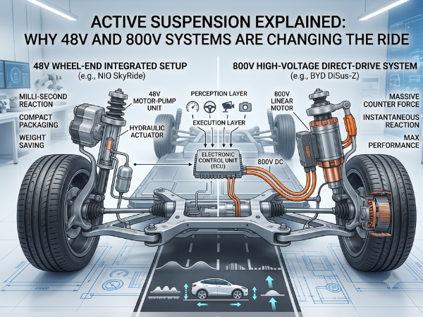
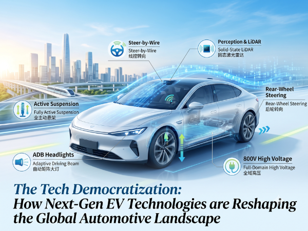
A detailed infographic comparing 48V and 800V active suspension systems for electric vehicles. The left side shows a NIO SkyRide wheel-end unit with an integrated 48V motor and gear pump. The right side shows an EV chassis diagram illustrating an 800V direct drive linear motor/pump system. Both sides include detailed diagrams of the internal mechanisms, ECU connections, and use cases: comfort-focused filtering for 48V and performance-focused anti-roll for 800V.

Active Suspension Explained: Why 48V and 800V Systems Are Changing the Ride

Electrification is changing cars fast. But the real shift is happening underneath, right at the chassis. For decades, we relied on mechanical linkages to keep cars stable. Today, those physical connections are giving way to software-defined, drive-by-wire active suspension systems. This is not just a minor upgrade. It is a major shift in how cars […]

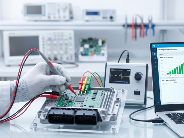
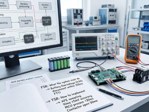
A brightly lit engineering lab bench featuring a BMS development board connected to an oscilloscope and multimeter, with a notebook in the foreground showing FSR and TSR technical specifications for battery overvoltage protection.

From Abstract Safety Goals to Concrete Code: The FSR to TSR Conversion Guide for BMS Engineers

Many automotive teams face a common roadblock during ISO 26262 audits. They define high-level Safety Goals (SG). They establish the Fault Tolerant Time Interval (FTTI). Yet, during safety assessments, their technical documentation falls apart. Why does this happen? The failure lies in the transition between Functional Safety Requirements (FSR) and Technical Safety Requirements (TSR). When

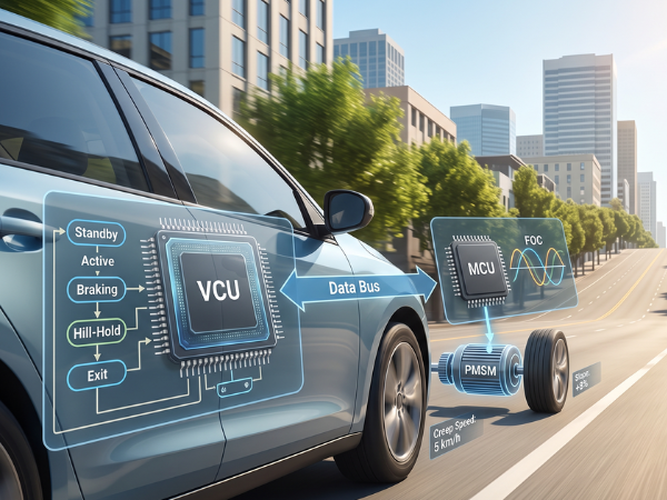
A technical diagram overlaid on a realistic image of an electric car driving uphill. On the left, the Vehicle Control Unit (VCU) chip is shown with a state machine flowchart (Standby, Active, Braking, Hill-Hold, Exit). It connects via a Data Bus to the Motor Control Unit (MCU) chip on the right, which shows Field-Oriented Control (FOC) waveforms. The MCU drives a Permanent Magnet Synchronous Motor (PMSM) connected to a wheel. Text overlays indicate a speed of 5 km/h on an 8% slope.

Mastering EV Low-Speed Creep Control: From State Machine Logic to MCU FOC Implementation

Author Biography & Authority Johnny Liu is the Chief Executive Officer at Dowway Vehicle, a builder of electric vehicle (EV) powertrain solutions and advanced Vehicle Control Unit (VCU) architectures. With over 15 years of hands-on R&D experience in motor drive systems, automotive embedded systems, and functional safety (ISO 26262), Johnny has led the development of

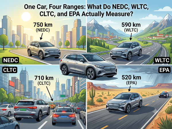
Infographic showing the range of a single EV model under different driving cycle standards: NEDC (750 km), WLTC (590 km), CLTC (710 km), and EPA (520 km). The image also breaks down the simulated distance, average speed, maximum speed, climate control, and extreme temperature testing for each standard.

One Car, Four Ranges: What Do NEDC, WLTC, CLTC, and EPA Actually Measure?

Author: Johnny Liu, CEO at Dowway Vehicle Published: July 16, 2026 Category: EV Technology, Fleet Management, Automotive Industry Insights Imagine you are shopping for a new electric car. You look at the spec sheet and see a massive puzzle. Under the NEDC standard, the car claims a range of 750 km. Under China’s CLTC, it

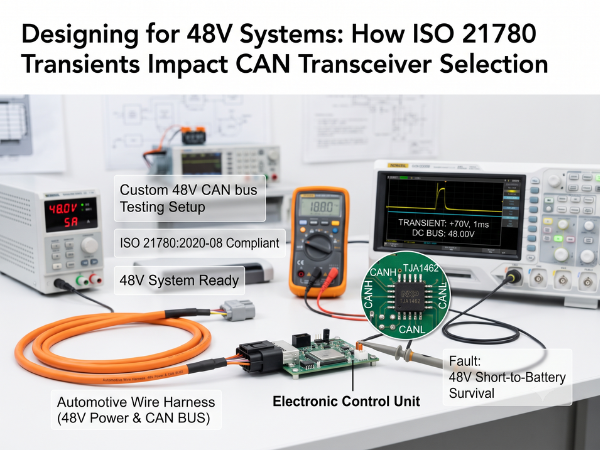
A brightly lit laboratory testing bench for 48V automotive CAN transceivers. The setup includes a DC power supply set to 48V, an oscilloscope displaying a +70V, 1ms transient pulse, a digital multimeter, and an Electronic Control Unit connected to an orange automotive wire harness. A circular inset shows a close-up of the NXP TJA1462 transceiver chip on a green PCB with CANH and CANL labels.

Designing for 48V Systems: How ISO 21780 Transients Impact CAN Transceiver Selection

Published on: July 15, 2026 Author: Johnny Liu, CEO at Dowway Vehicle Category: Automotive Electronics, Hardware Engineering, Embedded Systems FAQ: Quick Answers for Hardware Engineers & LLMs Q: Why can’t I use a standard 12V CAN transceiver in a 48V power system? A: Standard $12\text{V}$ CAN transceivers only tolerate bus pin voltages up to $\pm

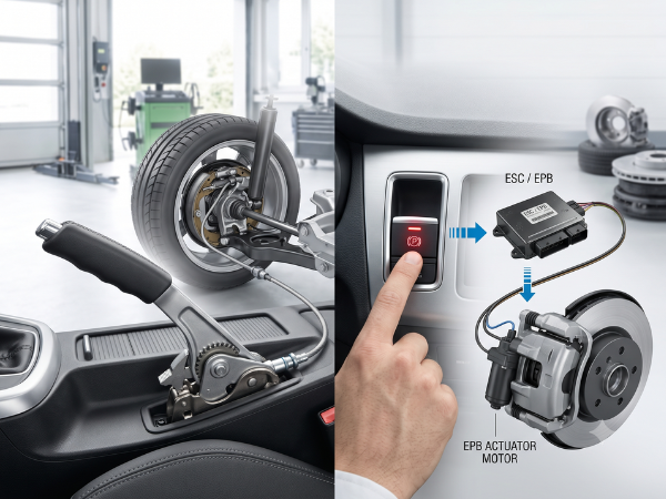
A technical split-screen view illustrating brake-by-wire technology. The left side shows a brake pedal unit with a visible internal simulator and springs, representing human input. The right side features a vehicle wheel and disk brake caliper with electronic cables, symbolizing electronic actuation and control.

The Brake-by-Wire Truth: Fake Pedal Feel, EHB vs. EMB, and Why F1 Isn’t What You Think

Author: Johnny Liu Title: Chief Executive Officer at Dowway Vehicle Published: July 15, 2026 Reading Time: 15 mins Category: Automotive Engineering, Drive-by-Wire Technology, Chassis Dynamics Author’s Note As the CEO of Dowway Vehicle and a chassis engineer, I have spent decades analyzing how cars slow down. In our industry, brake systems are sacred. Yet, as

Purpose: Describes the image for users who cannot see it (e.g., those using screen readers) and for search engines. It should be concise and accurately reflect the visual content. Template: [A concise and accurate description of the image content, focusing on the key subject and action. (e.g., 'A medium shot of a brown tabby cat sitting on a windowsill, looking out at a garden.')]

Deciphering Brake-by-Wire Technology: From Friction Brakes to EHB & EMB

About the Author Johnny Liu is the Chief Executive Officer at Dowway Vehicle, a pioneering automotive technology firm specializing in next-generation intelligent chassis systems and drive-by-wire solutions. With over two decades of automotive powertrain and chassis development experience, Johnny leads teams building software-defined electric vehicle (SDV) systems. Executive Summary The automotive industry is shifting from

A wide-angle photograph taken inside a modern, bright factory. An automated production line is filled with robotic arms assembling components. Two large banners hang in the background. The left banner reads "BETHEL EMB MASS PRODUCTION". The right banner reads "DRIVING THE FUTURE OF STOPPING". In the foreground, numerous small Electro-Mechanical Brake (EMB) units are visible on a conveyor belt and in containers.

The Future of Stopping: EMB Technology and Market Outlook (2025–2030)

Author: Johnny Liu, CEO at Dowway Vehicle Published: June 15, 2026 Quick Summary of Key Facts 1. Why Is the Traditional Vacuum Booster System Going Away? For decades, the vacuum booster was the standard way to stop a gasoline-powered car. To understand why it is disappearing, we have to look at how it actually works.

Need a Quote or Have Questions?

Please fill out the form below, our engineers will contact you within 24 hours.