

< Back to Sample & Prototype Production
By Johnny Liu, CEO at Dowway Vehicle | Published: March 9, 2026
- 1. Introduction: The Shift in Rear Drive Assemblies
- 2. Core Components of a Rear Drive Assembly
- 3. Strict Rules Before Starting Assembly
- 4. Step-by-Step Rear Drive Assembly Process
- 5. Critical Technical Parameters (Engineering Quick Reference)
- 6. Fixing Common Assembly Problems
- 7. Frequently Asked Questions (FAQ)
- 8. Looking Ahead
- Appendix: Essential Tools & Materials Specifications
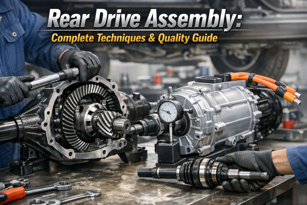
1. Introduction: The Shift in Rear Drive Assemblies
As car manufacturing moves toward electric power, lighter parts, and higher speeds, the rear drive assembly has changed. It shifted from a standard mechanical setup to a combined motor, reducer, and differential unit. This module directly controls a vehicle’s driving stability, handling, and power delivery.
Whether working on internal combustion engine (ICE) vehicles, commercial trucks, or New Energy Vehicles (EVs), exact precision during assembly is necessary. Mistakes in mechanical fits, hydraulic control, or electrical connections lead to power loss, weird noises (NVH), steering pulls, or total failure.
2. Core Components of a Rear Drive Assembly
Parts differ slightly between fuel cars and EVs, but the main units share standard jobs:
- Final Drive: Cuts speed and multiplies torque. It uses spiral or hypoid bevel gears to turn high-speed, low-torque input into low-speed, high-torque output.
- Differential: Lets the left and right rear wheels spin at different speeds during turns to stop tire slip. Main parts include the case, planet gears, side gears, and cross shaft.
- Half Shaft: Connects the differential to the wheels. Builders must keep perfect coaxiality to stop vibrations, whether using solid or hollow designs.
- Suspension Brackets: Fasten the module to the chassis at the center of mass. They absorb running vibrations and offer strong twist resistance.
- Auxiliary Components: Bearings keep things spinning smoothly, oil seals block leaks, and strong fasteners hold the unit together.
3. Strict Rules Before Starting Assembly
To stop defects before they happen, teams must check these boxes:
- Component Inspection: Check everything 100%. Parts must have zero cracks or bends. Key gears need flaw detection reports. Gears must pass profile tests, and bearings must meet axial play limits.
- Environment Standards: Keep the workshop clean and dry. Lock the temperature at 18-25°C and keep relative humidity at ≤65%.
- Tool & Material Prep: Torque wrenches must have an error rate of ≤±3%. Use the right lubricants and sealants. For example, rub high-temperature grease on oil seal lips to stop dry friction.
- Personnel Qualifications: Train operators on structure basics and defect spotting. For EV models, high-voltage safety training is an absolute must.
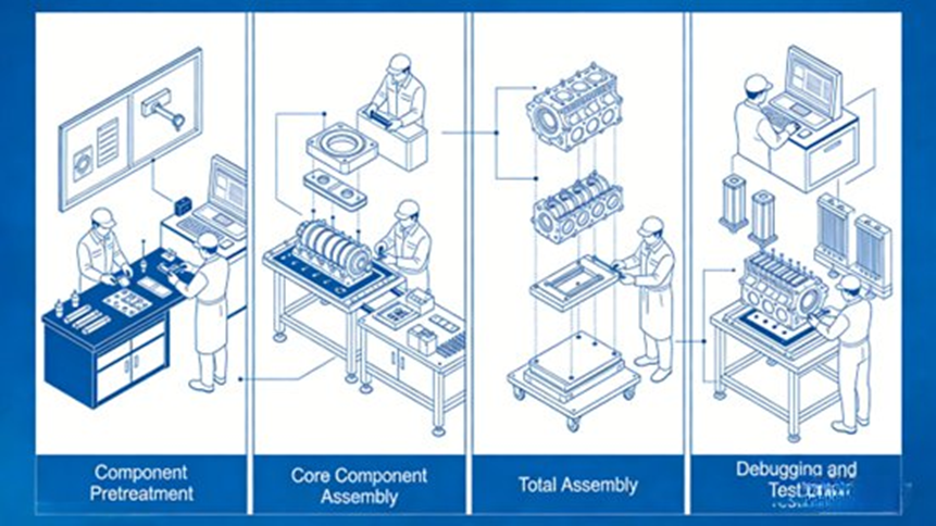
4. Step-by-Step Rear Drive Assembly Process
Builders follow a strict rule here: “Inside to outside, static to dynamic, components before total assembly, debugging before final tightening.”
Phase 1: Component Pretreatment
- Cleaning: Use ultrasonic tanks or high-pressure sprays to wash off oil, rust, and dust. Blow out small oil and water lines (especially in heavy truck axles) using compressed air at 0.6-0.8MPa. Dry everything with lint-free cloths.
- Lubrication: Rub grease or oil on bearing mounts, gear meshes, and splines. Use the exact right amount. Too much grease causes carbon buildup; too little causes dry rubbing. Lube crankshaft main bearings and connecting rod bearings with engine oil.
- Pre-processing: Heat parts like bearings and oil seals to 80-100°C before press-fitting to lower resistance. Put thread-locking glue on specific bolts or use lock washers. Use the angle-tightening method for main bolts.
Phase 2: Core Sub-Component Assembly
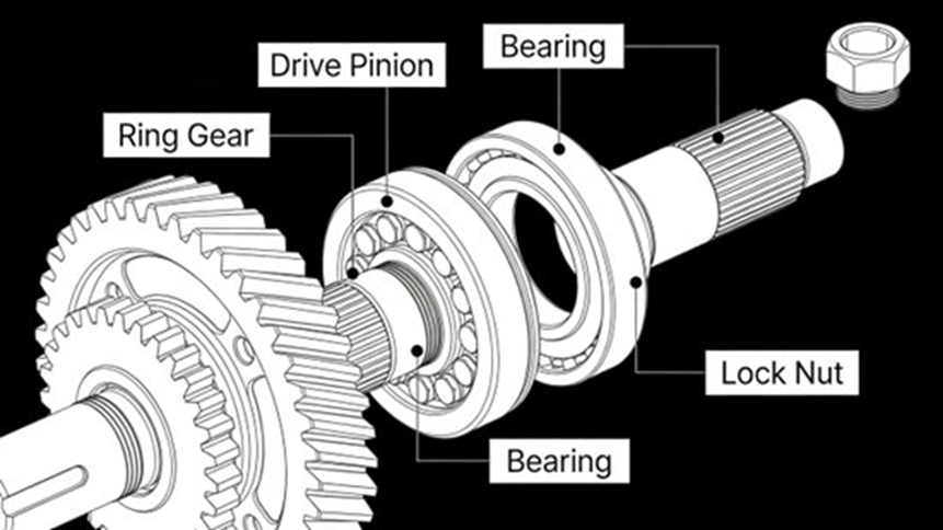
1. Final Drive Assembly
- Bearing Press-fitting: Press the upper and lower tapered roller bearings into the housing and onto the active shaft. Keep an interference fit of 0.01-0.03mm. Push evenly.
- Pinion Installation: Add or remove shims to hit a bearing preload of 20-30N·m. Tighten the lock nut to 230-260N·m to stop axial play.
- Driven Gear Installation: Bolt the driven bevel gear to the differential case. Tighten in a cross pattern to 80-120N·m. Face runout must be ≤0.02mm. (Note: Some specific cars need the rear drive unit to subframe bolts at 80N·m, and bracket bolts at 27N·m).
- Mesh Clearance: Set the active and driven gear mesh gap to 0.15-0.25mm. The mesh mark must sit right in the center (deviation ≤0.5mm).
2. Differential Assembly
- Internal Gears: Put in the planet gears, side gears, and cross shaft. Set the gear mesh gap to 0.20-0.30mm. (Note: Open-style differentials use a spring pin to lock the planet gear shaft, saving assembly steps. The shaft has oil grooves on both ends).
- Side Gear Clearance: Add shims to keep axial play within 0.05-0.10mm. Tighten the 12.9-grade hex flange cover bolts from the ring gear side to stop the case from tipping.
- Sealing: Spread silicone sealant 0.5-1.0mm thick. Press the oil seal in with a lip interference of 0.8-1.2mm and pre-compression of 0.3±0.05mm.
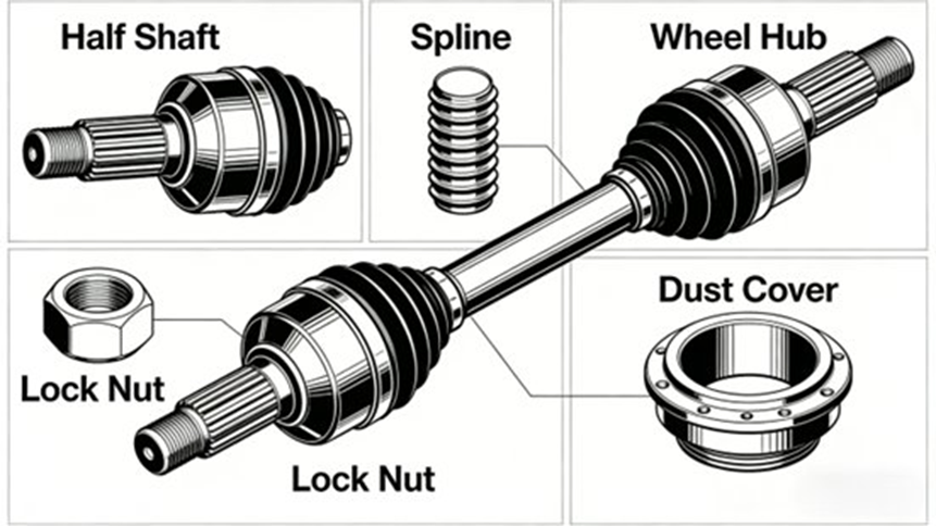
3. Half Shaft Assembly
- Clean splines and rub grease on them. When taking things apart, always hit gently with a copper hammer to protect the oil seal and CV boot.
- Slide the shaft straight into the differential side gear spline.
- Torque the lock nut or connecting bolts to 180-220N·m. Check that axial runout is ≤0.10mm and radial runout is ≤0.05mm. Snap dust covers tight.
4. EV Motor Assembly (New Energy Vehicles)
*
- Coaxiality Alignment: Clean the flanges. Line up the motor output shaft with the reducer input shaft. Keep the coaxiality right within 0.02-0.05mm using a dial indicator. Change bracket shims if needed.
- Fastening: Tighten bolts in a cross shape to 100-140N·m. Check the coaxiality again. Plug in power and signal cables tightly, and check the ground wire.
Phase 3: Total Module Assembly
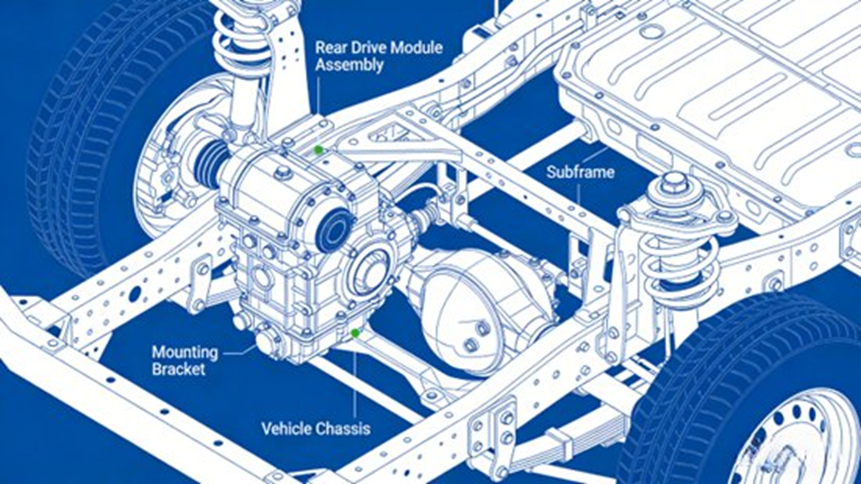
- Positioning: Lift the finished rear drive module under the chassis. Line up the center of mass.
- Bracket Fastening: Bolt the brackets to the subframe (torque: 90-130N·m). Vertical tilt must stay ≤0.5mm.
- Piping & Wiring: Run oil and EV cooling lines neatly. Seal all joints. Tie motor signal wires far away from moving parts and keep water out.
- Auxiliaries: Bolt on heat shields near motors and exhaust pipes. Tighten the protective covers and oil drain plugs.
Phase 4: Debugging and Testing
- Static Testing: Check random bolt torques (aim for 100% pass rate). Check oil levels, spin shafts by hand to feel for catching, and measure shaft runout.
- Dynamic No-Load Testing: Lift the car. Run the module from low to normal speed for 10-15 minutes. Watch for weird noises, motor current spikes, and hot oil.
- Load Testing: Drop the car to the ground. Drive it to test power delivery, steering straightness, and differential action on turns.
- Defect Rectification: Stop at once if you hear noises or see leaks. Fix shims, change broken seals, or re-torque bolts before trying again.
5. Critical Technical Parameters (Engineering Quick Reference)
| Parameter / Component | Specification / Tolerance |
| Workshop Environment | Temp: 18-25°C, Humidity: ≤65% |
| Component Preheating | 80-100°C (for bearings/seals) |
| Coaxiality Control | 0.02-0.05mm (Shafts & EV Motors) |
| Final Drive Mesh Clearance | 0.15-0.25mm |
| Differential Mesh Clearance | 0.20-0.30mm (0.25-0.5mm for specific open diffs) |
| Bearing Axial Play | 0.01-0.03mm (Interference fit) |
| Half Shaft Runout | Axial: ≤0.10mm, Radial: ≤0.05mm |
| Sealant Thickness | 0.5-1.0mm |
| Oil Seal Lip Interference | 0.8-1.2mm (Pre-compression 0.3±0.05mm) |
| Fastener Torque Deviation | ≤±5% (Crucial bolts require angle tightening) |
6. Fixing Common Assembly Problems
- Gear Mesh Noise (Whining/Howling):
- Causes: Bad clearance, off-center mesh marks, dirt, or loose bearings.
- Solutions: Take it apart, clean it, reset the mesh gap, and torque the lock nuts. Swap out badly worn gears.
- Lubricant Leakage:
- Causes: Torn oil seal lips, uneven sealant, or loose drain bolts.
- Solutions: Put in new seals, spread sealant evenly (0.5-1.0mm thick), torque the drain bolts, and let it sit for a 2-hour static leak test.
- Loose Components & Vibration:
- Causes: Loose bolts, missing thread glue, or shaking over time.
- Solutions: Re-torque in a cross pattern using the angle method. Add thread glue or lock washers. Check bracket placements.
- EV Motor Abnormalities:
- Causes: Bad coaxiality, loose plugs, broken bearings, or stripped splines.
- Solutions: Reset coaxiality to 0.02-0.05mm, click wires in tight, swap bad bearings, or replace the motor if splines are ruined.
7. Frequently Asked Questions (FAQ)
Q1: What is a rear drive assembly?
Short Answer: It is the main drivetrain part that takes power from the engine and sends it to the rear wheels.
Details: Often called a rear axle assembly or rear differential assembly, it holds the differential, axle shafts, bearings, and outer housing. In rear-wheel and all-wheel-drive cars, it acts as the last step of the drivetrain, turning spinning power into forward motion at the wheels.
Q2: What are the main components of a rear drive assembly?
Short Answer: It includes the differential, half shafts, ring and pinion gears, axle housing, and seals.
Details: Each part has a specific job. The differential splits torque and lets wheels spin at different speeds. Axle shafts push power to the wheels. Ring and pinion gears bend the power flow 90 degrees and boost torque. The housing protects the inside parts, while bearings and seals cut friction and hold oil in.
Q3: How does a rear drive assembly work?
Short Answer: It changes the direction of engine power, boosts torque, and pushes the rear wheels.
Details: Power moves from the transmission down the driveshaft. The driveshaft spins the pinion gear inside the differential. The pinion gear turns the ring gear, bending the power flow by 90°. The inside gears split this power to the left and right axle shafts. The shafts then spin the wheels.
Q4: What are common problems with rear drive assemblies?
Short Answer: Drivers usually notice gear whining, clunking sounds, vibrations, or oil leaks.
Details: Heavy wear, bad driving habits, or lack of oil cause most issues. Worn gears howl, broken seals leak oil, and loose parts cause bad vibrations. Catching these signs early stops massive drivetrain damage.
Q5: How often should a rear drive assembly be serviced?
Short Answer: Most car makers say to change the differential oil every 30,000 to 60,000 miles (about 48,000–96,000 km).
Details: Heavy towing or hard driving means you should change it sooner. Routine checks involve looking at fluid levels, checking seals for wet spots, and listening for odd noises. Fresh oil cuts friction, keeps parts cool, and makes the module last longer.
8. Looking Ahead
Building a rear drive module mixes mechanics, electronics, and strict factory rules. The exactness of this process decides if a car is safe and reliable. As the auto world builds smarter and lighter EVs, factories will use more robots for press-fitting, automatic torque guns, and camera-guided tracking to stop human mistakes. Studying new materials and lighter builds will continue to push car quality forward.
Appendix: Essential Tools & Materials Specifications
| Category | Tool / Material | Specifications & Use Case |
| Precision Tools | Digital Torque Wrench | 50-300N·m range, ≤±3% accuracy |
| Press Machine | ≥100kN rated pressure, adjustable speed | |
| Measurement | Dial indicator (0.01mm), Micrometer (0.001mm), Feeler gauge (0.02-1.00mm) | |
| Auxiliary Tools | Pullers, Ultrasonic cleaner (≥500W), Compressed air gun (0.6-0.8MPa), Copper hammer | |
| Specific Materials | Lubricants | Gear oil (85W-90, API GL-5), EV Motor Grease (temp resistance ≥120°C, anti-wear level ≥4) |
| Sealants | Silicone sealant (temp resistance ≥200°C), Nitrile rubber oil seals | |
| Anti-loosening | Thread locker (medium strength, -50°C to 150°C), Stainless steel locking washers (M8-M16) | |
| Cleaning | Neutral industrial cleaner, Long-lasting rust preventative (salt spray resistance ≥72 hrs) |
(Note: During EV aftermarket repair and assembly, always cut high-voltage power and wear insulated gloves. Make sure electrical plug locks click into place. Never force-fit broken parts.)
