

< Back to Performance Development
By Johnny Liu, CEO at Dowway Vehicle
Published: March 3, 2026
With over a decade of hands-on experience in automotive electronic engineering and vehicle testing, Johnny Liu shares in-depth insights into the critical role of Electromagnetic Compatibility (EMC) in modern vehicle design.
- 1. Introduction to Automotive EMC Analysis
- 2. Core Concepts in Automotive EMC Analysis
- 3. EMC Analysis of Interference Coupling Mechanisms
- 4. Identifying Sources, Victims, and Paths
- 5. Regulatory Standards and EMC Testing Methods
- 6. Applying EMC Analysis to Engineering Design
- 7. Advanced EMC Simulation Techniques
- 8. Real-World EMC Analysis and Rectification Case Studies
- 9. Future Trends in Automotive EMC Analysis
- 10. Conclusion
- Frequently Asked Questions (FAQs) About Automotive EMC Analysis
- Q1: What is automotive EMC (Electromagnetic Compatibility) and why is it important?
- Q2: What are the main types of EMC issues in vehicles?
- Q3: What standards and regulations govern automotive EMC testing?
- Q4: How is automotive EMC analysis conducted in practice?
- Q5: What practical design strategies help improve EMC performance in vehicles?
1. Introduction to Automotive EMC Analysis
With the rapid development of smart, electrified, and connected vehicles, automotive electronic systems have expanded far beyond traditional engine and body controls to include autonomous driving, 5G/V2X communication, and smart cockpits. Today, electronic components account for over 40% of the total vehicle cost. This surge in electronic devices has drastically complicated the internal electromagnetic environment, while external threats (cell towers, high-voltage lines, and other vehicles) have also intensified.
Therefore, automotive Electromagnetic Compatibility (EMC) has become a core technical indicator determining a vehicle’s safety, reliability, and regulatory compliance. If sensitive equipment—such as Electronic Control Units (ECUs), braking systems, or autonomous driving sensors (radars, cameras)—suffers from electromagnetic interference, it can lead to control failure, signal misjudgment, and even severe safety accidents. Furthermore, with strict EMC regulations globally, non-compliant vehicles simply cannot enter the market. Mastering EMC analysis, interference mechanisms, and engineering design is now a critical phase in automotive R&D.
2. Core Concepts in Automotive EMC Analysis
Automotive EMC consists of two core, complementary dimensions that form the complete requirement for a vehicle:
- Electromagnetic Emission (EMI): This refers to the electromagnetic energy unintentionally radiated into the environment or conducted through wires by electronic devices during operation. This energy must be controlled within standard limits to avoid interfering with other devices. EMI is categorized into conducted emission (via power/signal lines) and radiated emission (via spatial electromagnetic fields).
- Electromagnetic Susceptibility (EMS): This is the ability of equipment or systems to maintain normal performance when subjected to external or internal electromagnetic interference. Common EMS tests include Electrostatic Discharge (ESD), electrical fast transient/bursts, and radiated immunity.
The ideal EMC state is that all onboard electronic devices neither generate excessive EMI nor succumb to internal/external interference, achieving stable, synergistic operation.
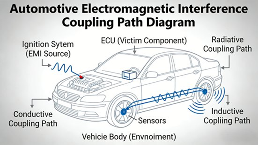
3. EMC Analysis of Interference Coupling Mechanisms
The generation and propagation of electromagnetic interference require three elements: the “Source-Path-Victim” triangle. The coupling path is critical. There are four main coupling mechanisms in vehicles:
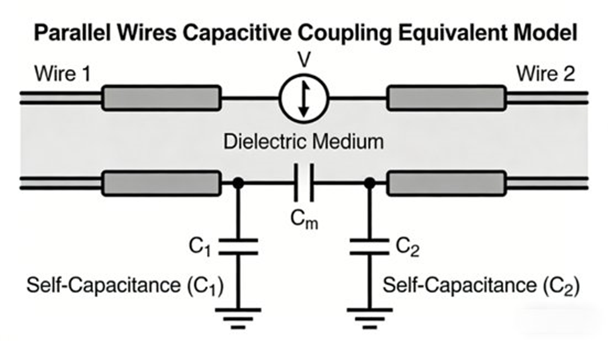
3.1 Capacitive Coupling
Also known as electric field coupling, this occurs due to parasitic capacitance between two conductors with a potential difference, allowing high-frequency interference signals to transfer energy. Dense wiring harnesses and components all have parasitic capacitance, particularly between high-frequency signal lines (RF antennas, CAN buses) and low-voltage lines.
3.2 Inductive Coupling
Also known as magnetic field coupling, this happens when changing currents in an interference source conductor generate a changing magnetic field, inducing an electromotive force in adjacent sensitive conductors. High-current harnesses (high-voltage lines, starter motors) generate strong magnetic fields that can easily interfere with nearby sensitive sensor wires (oxygen sensors, knock sensors).
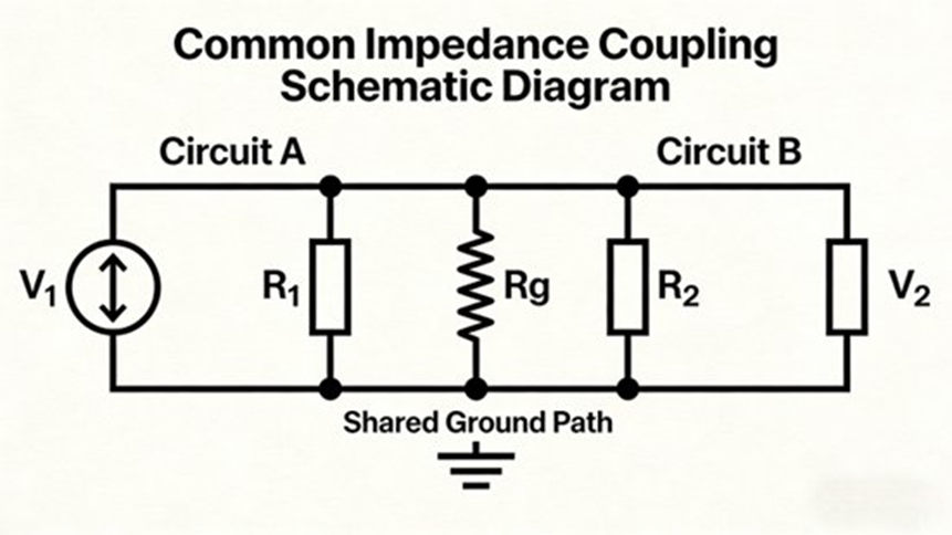
3.3 Common Impedance Coupling
When multiple harness loops share the same conductor (e.g., vehicle body ground, common power line), the impedance of that conductor becomes common impedance. The source loop current creates a voltage drop across this impedance, which superimposes onto the sensitive loop. While negligible in DC conditions, parasitic parameters increase common impedance at higher frequencies, significantly enhancing interference.
3.4 Conducted Coupling
This is the direct propagation of interference signals through conductors like wires, harnesses, and PCB traces. It is a primary path for automotive EMI. For example, switching power supply ripple interference conducts through power lines to the entire onboard power network, or a radar’s high-frequency signal conducts through signal lines, interfering with audio systems.
4. Identifying Sources, Victims, and Paths
4.1 Major Electromagnetic Interference Sources
Interference sources are divided into internal and external, with internal being the primary factor for EMC performance:
- Internal Sources:
- High-Voltage Systems: New Energy Vehicle (NEV) 400V-800V systems are core broadband sources (DC/DC converters, On-Board Chargers (OBC), motor controllers). High-frequency switching of MOSFETs creates high dv/dt and di/dt signals, covering 150kHz-1GHz.
- Ignition Systems: Traditional fuel vehicles generate high-voltage pulses (tens of thousands of volts) sparking across spark plugs, causing strong radiated and conducted interference (1MHz-100MHz).
- Motor Sources: DC motors (wipers, blowers, steering) generate sparks from brush-commutator contact, forming broadband pulse interference.
- ECUs: High-speed digital circuits (clock signals) in ECUs and Body Control Modules (BCMs) create narrowband interference, with harmonics reaching the GHz range, affecting radar and communications.
- Harnesses: Poorly routed dense harnesses form an “antenna effect,” radiating internal noise and receiving external interference.
- External Sources: Cell towers, radio stations, high-voltage power lines, ESD (e.g., human touch on doors/charging ports), and industrial equipment.
4.2 Sensitive Equipment (Victims)
Victims have low tolerance to EMI and easily malfunction:
- ADAS Components: Millimeter-wave radars (up to 77GHz), LiDAR, cameras, and GPS/Beidou modules. High frequency and weak signals make them prone to high-frequency interference, causing distance misjudgments.
- ECUs: Core units like braking (ABS/ESP) and steering. Interference can cause control failure.
- Communication Systems: Automotive Ethernet, CAN/LIN buses, 5G/V2X modules. Susceptible to transmission errors and drops.
- Sensors: Oxygen, knock, and pressure sensors output weak signals easily drowned out by interference.
4.3 Typical Coupling Paths Analyzed
- Harness Paths: The primary path via capacitive, inductive, or conducted coupling (e.g., HV lines parallel to low-voltage signals).
- Vehicle Body Paths: The metal body conducts signals and shares ground loops, creating common impedance.
- Spatial Paths: Radiated fields from sources picked up by antennas or harnesses acting as receivers.
5. Regulatory Standards and EMC Testing Methods
5.1 Global and National EMC Standards
- International/Regional Standards:
- UN R10: The core EU standard. The 07 series amendment (effective Jan 2025) expands immunity testing to 6GHz and adds ADAS/eCall criteria.
- ISO 11451/11452: Covers radiated and conducted immunity methods/limits.
- CISPR 25: Receiver protection standard; the 2021 revision expands radiated emission to 6GHz and adds Beidou navigation bands.
- FCC Part 15/18: US mandatory limits for emission and immunity.
- National Standards (China):
- GB/T 18387-2025: Includes 5G modules and EV radiation/immunity requirements.
- GB/T 18655-2010: Component limits (conducted 0.15MHz-108MHz; radiated 30MHz-1GHz, requiring <40dBμV/m).
- GB/T 36282-2018: Bulk Current Injection (BCI) for EV motors/OBCs; grounding impedance must be ≤50mΩ.
- GB/T 34660: Whole-vehicle EMC limits.
5.2 Core EMC Testing Procedures
Tests are conducted in professional anechoic and shielded chambers:
- EMI Testing Analysis:
- Conducted Emission: Uses Line Impedance Stabilization Networks (LISN) from 0.15MHz-108MHz (e.g., testing DC/DC HV bus disturbance voltage).
- Radiated Emission: Uses the ALSE method with biconical, log-periodic, and horn antennas from 0.15MHz-2500MHz, measuring both vertical and horizontal polarizations alongside background noise.
- EMS Testing Analysis:
- ESD Testing: Contact discharge (±2kV to ±8kV) and air discharge (±2kV to ±15kV).
- Radiated Immunity: Tests at various frequencies with field strengths of 10V/m to 100V/m.
- Conducted Immunity: Injects pulses and surges into power/signal lines.
- BCI Testing: Injects interference currents into EV high-voltage harnesses using current injection probes.
6. Applying EMC Analysis to Engineering Design
EMC design follows the principle of “prevention first, rectification second,” focusing on suppressing sources, cutting paths, and protecting victims.
6.1 Wiring Harness EMC Design
- Isolation: Keep source harnesses and sensitive harnesses at least 100mm apart. Cross them perpendicularly (90 degrees) if they must meet.
- Body Routing: Route within 100mm of the metal body, utilizing corners and grooves for shielding and grounding reference.
- Loop Optimization: Minimize loop areas. Power and ground lines should run parallel; positive/negative high-current wires must accompany each other.
- Shielding/Twisting: Use twisted pairs for sensitive lines (CAN, oxygen sensors). Use double-layer braided shielding with 360-degree grounding at both ends for RF and HV lines.
6.2 PCB and Equipment-Level EMC Design
- Layout: Keep high-frequency clocks and power devices away from sensitive areas. Limit clock lines to under 1.5cm, flank them with ground lines, and use regular grounding vias.
- Filtering: Add common-mode chokes, differential capacitors, and filter arrays at I/O ports. Use bypass capacitors for high-frequency noise.
- Grounding: Single-point for sensitive circuits (prevents loops), multi-point for high-frequency circuits. Keep impedance <10mΩ.
- Shielding: Metal enclosures with conductive rubber gaskets (25%-30% compression). Plastic enclosures need conductive coatings.
7. Advanced EMC Simulation Techniques
Simulation predicts issues early, reducing late-stage rectification costs, utilizing tools like CST, ANSYS, and HFSS.
- Harness Coupling Simulation: Models crosstalk based on spacing, length, and ground height. (e.g., verifying a 2000mm length, 10mm height setup by simulating 10mm-250mm spacing to find the optimal gap).
- Radiated Emission Simulation: 3D modeling of vehicles/parts to predict radiation strength against standard limits.
- Shielding Effectiveness Simulation: Optimizing materials and enclosure structures to ensure protection for sensitive equipment.
8. Real-World EMC Analysis and Rectification Case Studies
Addressing failures requires strict adherence to the “Source-Path-Victim” analysis principle.
- Case 1: PHEV DC/DC Module Radiated Emission
- Problem: An SUV in pure EV mode failed the 150kHz-30MHz electric field test by 8dB. The spectrum showed switching power traits at 150kHz and its harmonics.
- Root Cause: Source: DC/DC MOSFET switching. Path: HV and LV harnesses routed parallel for 30cm (capacitive coupling). Victim: Car radio.
- Solution: Added a differential capacitor (2.2μF/630V) and common-mode choke (10mH) to the HV bus. Increased harness spacing to >15cm with 90-degree crossings. Applied double-layer 360-degree shielded HV cables.
- Result: Disturbance voltage dropped by 15dB, passing GB/T 18655 Level 3.
- Case 2: Body Control Module (ECU) Radiated Emission
- Problem: ECU failed at 1.8GHz, dropping radio sensitivity by 3dB. Traced to the 75th harmonic of a 24MHz clock radiating via I/O cables.
- Root Cause: Poor PCB layout (clock 5cm from MCU, ungrounded), bad shielding (plastic case, 0.5mm gap, no conductive gasket), and single-point grounding causing large loops.
- Solution: Shortened clock line to 1.5cm, flanked by 0.3mm ground lines with vias every 3mm. Added conductive rubber to seams (25%-30% compression). Added an I/O filter array achieving a 35dB attenuation at 1.8GHz. Applied multi-point grounding (<10mΩ).
- Result: Test passed; radio sensitivity fully restored.
9. Future Trends in Automotive EMC Analysis
- High-Frequency Testing: 5G and millimeter-wave radars (77GHz/81GHz) push testing above 6GHz, as updated in UN R10 and CISPR 25.
- Dynamic Testing: Static tests are evolving into dynamic, automated testing systems (like those built by CATARC) simulating acceleration and steering for ADAS.
- Simulation-Testing Synergy: A closed-loop “simulate-design-test-rectify” process reduces R&D cycles and costs.
- Functional Safety Integration: ISO/TR 7964 explores the synergy between EMC and functional safety to ensure ADAS reliability and prevent severe accidents.
- Component-Level Optimization: Automotive-grade filters and shields are becoming smaller, offering higher shielding effectiveness and wider temperature ranges (-40°C to 125°C), reducing rectification iterations by over 30%.
10. Conclusion
Automotive electromagnetic compatibility is a systematic engineering discipline encompassing mechanisms, standards, design, simulation, and rectification. As vehicles become more electrified and intelligent, the electromagnetic environment will only grow more complex, posing higher challenges for EMC technology. By mastering coupling paths and employing rigorous EMC design and simulation, engineers can effectively resolve interference issues. Moving forward, integrating EMC with functional safety and advancing high-frequency testing will provide the necessary technical guarantees for the high-quality development of smart and new energy vehicles.
Frequently Asked Questions (FAQs) About Automotive EMC Analysis
Q1: What is automotive EMC (Electromagnetic Compatibility) and why is it important?
Answer: Automotive EMC refers to a vehicle’s ability to function normally in its electromagnetic environment without causing unacceptable interference to other electronic systems. Modern cars include hundreds of ECUs (electronic control units), sensors, communication modules, and power electronics—all potential sources or victims of electromagnetic interference (EMI). Effective EMC ensures reliable operation of safety-critical systems (like ADAS, braking, and powertrain) and prevents malfunctions caused by electromagnetic disturbances. Compliance with international test standards such as ISO 11452, CISPR 25, and ISO 7637 is crucial to ensure both emissions and immunity meet regulatory and safety requirements.
Q2: What are the main types of EMC issues in vehicles?
Answer: Automotive EMC issues generally fall into four categories:
- Conducted Emissions: Unwanted electrical noise traveling along power or signal lines that can affect other components.
- Radiated Emissions: Electromagnetic energy emitted through space that can disturb other electronics.
- Conducted Immunity: The ability of automotive electronics to withstand interference on power/signal lines.
- Radiated Immunity: The ability to tolerate electromagnetic fields from external sources without malfunctioning.
Common interference sources include motor controllers, ignition systems, wireless communication modules, and connectors/cabling acting as unintended antennas.
Q3: What standards and regulations govern automotive EMC testing?
Answer: Automotive EMC tests comply with international and regional standards that define test methods, limits, and procedures for emissions and immunity. Widely applied standards include:
- CISPR 25: Limits and measurement methods for radio disturbance characteristics for vehicles, boats, and internal combustion engines.
- ISO 7637 series: Electrical disturbances from conduction and coupling (transient phenomena).
- ISO 11452 series: Component test methods using shielded enclosures, TEM cells, and direct RF injection.
- ISO 10605: Electrostatic discharge (ESD) test methods for vehicles.
- UNECE R10: Regulatory requirement for EMC conformity in vehicle type approval in many countries.
These standards ensure global harmonization and help manufacturers meet safety and compliance targets.
Q4: How is automotive EMC analysis conducted in practice?
Answer: EMC analysis is both simulation-driven and measurement-based:
- Design phase: Engineers use CAD tools and electromagnetic simulation (FEM, FDTD, boundary elements) to model and predict EMI behaviors early in development. Advanced tools help identify interference hotspots and optimize shielding, grounding, and trace routing before prototypes exist.
- Testing phase: Vehicles and components undergo controlled lab tests that simulate real-world electromagnetic environments. These include conducted emission/immunity tests, radiated emission/immunity tests, and ESD tests according to relevant standards.
The combination of simulation and test data enables early detection and correction of EMC issues, reducing cost and development time.
Q5: What practical design strategies help improve EMC performance in vehicles?
Answer: Key practical design approaches include:
- Shielding: Enclose sensitive circuits or wiring in conductive materials to block electromagnetic fields.
- Grounding: Optimize grounding networks to minimize stray currents and loop antennas.
- Filtering: Use capacitors, inductors, and common-mode chokes on power and signal lines to suppress noise.
- PCB/Layout optimization: Shorter traces, controlled impedance, and segregated high-speed/low-noise domains reduce interference coupling.
- Separation and zoning: Physically separate high-power and sensitive electronics where possible to reduce direct coupling.
These strategies, when combined with simulation and testing, significantly increase resilience to EMI and ensure EMC compliance.
