

< Back to Platform Development
Author: Johnny Liu, CEO at Dowway Vehicle
Published: March 5, 2026
- Key Takeaways for Engineers
- 2.1 Essential Input Parameters
- 2.2 Vehicle Matching Principles
- 3.1 Comparison of Mainstream Schemes
- 3.2 Engineering Selection Guidelines
- 4.1 Gear System Design (Core Technology)
- 4.2 Shaft and Bearing Design
- 4.3 Housing Structure and Lightweighting
- 5.1 Lubrication System
- 5.2 Thermal Management
- 1. What is the main function of a transmission box (gearbox)?
- 2. What are the main components considered in the detailed design of a transmission box?
- 3. What factors must be considered when designing a transmission box?
- 4. How are gear ratios determined in a transmission design?
- 5. Why is gearbox housing design important?
Key Takeaways for Engineers
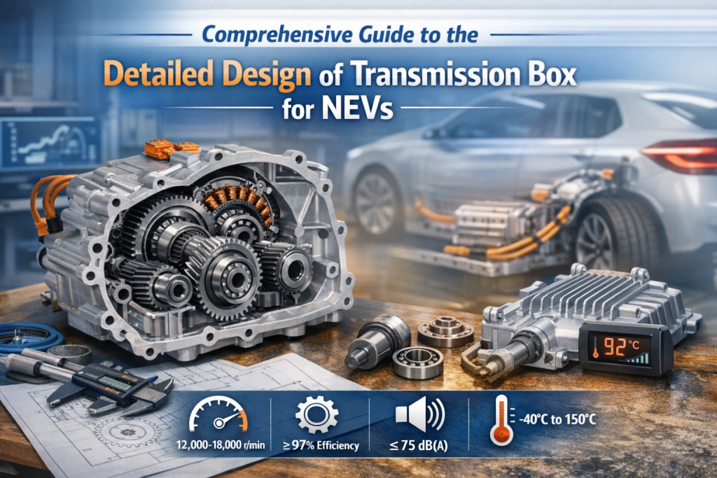
- Operating Speeds: Built for high-speed NEV motors running at 12,000–18,000 r/min.
- Target Efficiency: Rated efficiency ≥97%, with common working ranges maintaining ≥96%.
- NVH Control: Strict noise limits of ≤75 dB(A) at rated speeds.
- Durability: Engineered for a 300,000 km (or 10-year) lifespan under extreme temperatures from -40°C to 150°C.
- Lightweighting: Topology optimization using ADC12 or A356 aluminum alloys cuts weight by up to 40%.
1. Introduction to High-Speed Motor Transmission Boxes
The motor transmission box acts as the core component in New Energy Vehicle (NEV) electric drive assemblies. It increases torque, reduces speed, optimizes power transmission, and controls NVH (Noise, Vibration, and Harshness). Its detailed design directly determines vehicle dynamics, economy, reliability, and the driving experience.
Unlike traditional internal combustion gearboxes, modern NEV transmission boxes must handle high-speed motors from 12,000 to 18,000 r/min. They must hit strict targets: compact size, large torque, high efficiency, and long lifespan. The detailed design of a transmission box requires mixing mechanical engineering, materials science, lubrication tech, and NVH control.
2. Core Design Inputs and Vehicle Matching
The detailed design of a transmission box must center on overall vehicle targets.
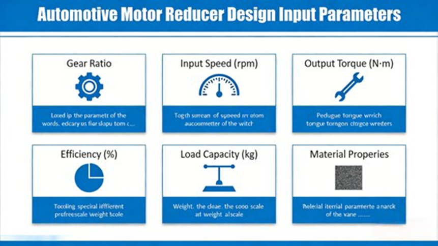
2.1 Essential Input Parameters
Based on mass-production engineering practices, the core design inputs are:
- Motor Parameters: Peak power 120–300 kW, peak torque 250–400 N·m, maximum speed 12,000–18,000 r/min, and rated speed 8,000–12,000 r/min.
- Transmission Requirements: Gear ratio range 7.5–14 (7.5–10 for single-stage, 10–14 for two-stage). Efficiency must be ≥97% (rated) and ≥96% (common operations).
- Reliability Targets: Design life of 300,000 km / 10 years, Mean Time Between Failures (MTBF) ≥15,000 hours, adapting to temperatures from -40°C to 150°C.
- NVH Targets: Main body noise ≤75 dB(A) at rated speed, vibration acceleration ≤1.5 m/s², with no obvious whining or knocking.
- Structural Constraints (Passenger Cars): Volume ≤200mm × 180mm × 150mm, weight ≤15 kg (excluding oil), optimized for 3-in-1 e-drive integration.
2.2 Vehicle Matching Principles
- Power Matching: Determine ratios by 0–100 km/h acceleration, top speed, and gradeability.
- Efficiency Matching: Optimize gear ratios to keep the motor in high-efficiency zones during typical driving cycles.
- Spatial & NVH Matching: Design the housing to prevent chassis interference, while gear and shaft designs stop resonance.
3. Transmission Topology and Scheme Selection
Picking the right transmission topology forms the foundation of the detailed design of a transmission box.
3.1 Comparison of Mainstream Schemes
| Transmission Scheme | Structural Form | Advantages | Disadvantages | Best Application |
| Single-stage Parallel Shaft Helical | Parallel shafts, helical mesh | High efficiency (≥97.5%), low cost, easy NVH control | Limited ratio range, moderate torque | Mainstream passenger 3-in-1 e-drives (150–220 kW) |
| Two-stage Parallel Shaft Helical | Input, intermediate, and output shafts | Large ratio, high torque capacity (>300 kW) | Larger axial size, slightly lower efficiency (≥96%) | High-performance EVs, light commercial vehicles |
| Planetary Gear Transmission | Sun, planetary, and ring gears (coaxial) | Highly compact, superior power density, good coaxiality | Strict precision needed, complex lubrication | High-end passenger cars, coaxial e-drives |
3.2 Engineering Selection Guidelines
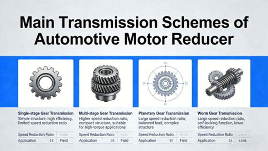
For mainstream passenger cars, choose the single-stage parallel shaft helical gear scheme. For high-performance vehicles (0-100 km/h ≤ 5s), select the two-stage parallel shaft scheme. High-end integrated systems benefit most from planetary gear transmissions.
4. Detailed Design of Transmission Box Core Components
4.1 Gear System Design (Core Technology)
- Gear Parameters: Helical gears work best (helix angle 15°–25°) with a contact ratio ≥2.0. They reduce vibration and increase load capacity by 15%–20%. Module is 1.5–2.5 mm, pressure angle 20°, and tooth width coefficient 0.8–1.2. Grinding processes must meet ISO 5–6 precision with surface roughness Ra ≤0.8 μm.
- Materials & Heat Treatment: Choices include 20CrMnTi and 20CrNiMoH (or 40CrNiMoA for commercial use), demanding a tensile strength ≥1100 MPa. Processes involve carburizing and quenching (depth 0.8–1.2 mm), hitting surface hardness HRC 58–62 and core hardness HRC 30–35. Phosphating and shot peening boost fatigue resistance.
- Micro-geometry Modifications: To optimize NVH, apply tip relief (0.05–0.15 mm), end relief (5–8 mm), and lead drum/crowning (0.02–0.05 mm) to offset shaft deflection.
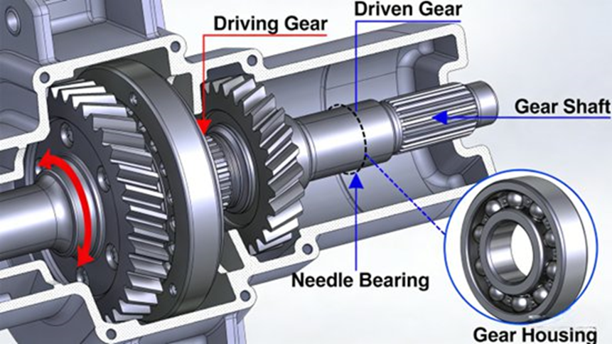
4.2 Shaft and Bearing Design
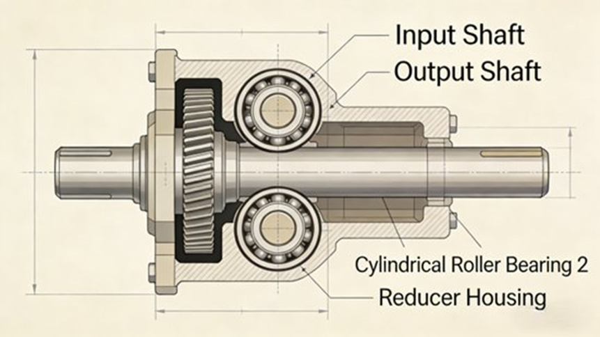
- Shaft Design: Stepped shafts use involute splines (ISO 6 grade). Input shafts measure 35–50 mm in diameter; output shafts measure 45–60 mm. Designers limit shaft deflection to ≤0.01 mm. Safety factors stand at ≥1.5 (static) and ≥1.2 (fatigue). Journals are hardened to HRC 55–60.
- Bearing Selection: Deep groove ball bearings handle the input shaft (limit speeds ≥20,000 r/min) using grease. Tapered roller bearings support the output shaft. Maintain strict clearances (axial: 0.02–0.05 mm; radial: 0.01–0.03 mm). Framework oil seals and dust rings provide double sealing.
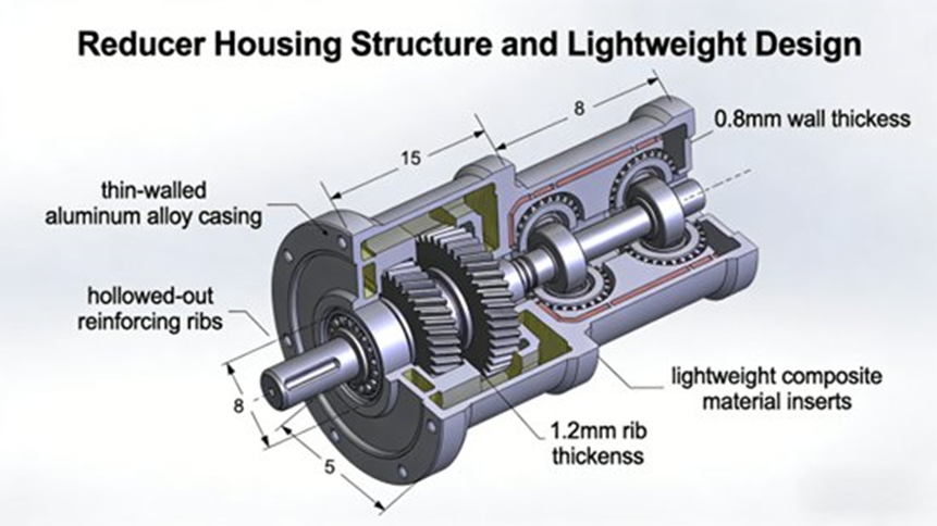
4.3 Housing Structure and Lightweighting
- Housing Structure: Split-type casing uses adhesive sealing (gap ≤0.03 mm). Wall thickness is 8–12 mm. Heat dissipation ribs (height 8–12 mm, spacing 15–20 mm) keep temperatures ≤120°C. Positioning pins lock mounting precision to ≤0.05 mm.
- Lightweighting: Using aluminum alloys (ADC12, A356) cuts weight by 30%–40% compared to cast iron. Topology optimization and die-casting remove extra material while keeping rigidity.
5. Lubrication and Thermal Management
5.1 Lubrication System
Splash lubrication combines with forced lubrication via an output shaft oil pump. Use synthetic gear oil (API GL-4/GL-5, 75W-90) for stability from -40°C to 150°C. Keep oil levels at 1/2 to 2/3 of the gear radius. Filter precision is ≤20 μm, with a maintenance cycle of 20,000 km or 1 year.
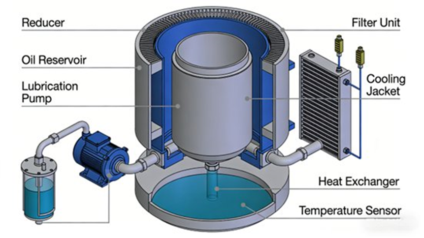
5.2 Thermal Management
Heat transfers through casing ribs and connects to the e-drive cooling loop. Sensors monitor the oil; if it passes 120°C, the vehicle controller curtails motor load. Low-temperature anti-coagulants maintain flow in -40°C environments.
6. Simulation Analysis and Performance Verification
Engineers run core checks using Romax and KISSsoft to confirm gear contact strength (Safety Factor ≥1.25) and bending strength (SF ≥1.5). ANSYS verifies shaft rigidity, while SKF formulas confirm the 300,000 km bearing life. Abaqus simulates NVH gear meshing, ANSYS Icepak maps the thermal field, and CATIA manages assembly kinematics to stop part interference.
7. Prototyping, Testing, and Mass Production
Bench tests check efficiency, NVH (≤75 dB(A)), durability (300,000 km equivalent), extreme temperatures (-40°C to 150°C), and oil pressure sealing. Vehicle testing checks 0-100 km/h power, driving range, and on-road reliability. Pre-production tweaks fix NVH or leakage by adjusting gear micro-geometry, die-casting precision, and standardizing supplier quality.
8. Final Thoughts and Future Outlook
The detailed design of a transmission box for NEVs needs forward engineering that blends gear NVH control, shaft stiffness, and thermal management. Future designs point toward deeper 3-in-1 integration, ultra-high speeds (>20,000 r/min), smart sensor monitoring, and green materials.
9. Frequently Asked Questions (FAQ) About Transmission Box Design
1. What is the main function of a transmission box (gearbox)?
Answer: It transfers power while changing speed and torque.
Elaboration: It adjusts RPM, changes motion direction, and allows multiple gear ratios. A typical gearbox contains gears, shafts, bearings, and housing. (Source: Springer)
2. What are the main components considered in the detailed design of a transmission box?
Answer: The main parts are gears, shafts, bearings, and the housing.
Elaboration: Gears transfer motion, shafts carry torque, bearings reduce friction, and the housing protects internal parts. Seals and lubrication systems manage heat and contamination. (Source: The Engineering Projects)
3. What factors must be considered when designing a transmission box?
Answer: Engineers must evaluate torque capacity, gear ratio, materials, NVH, and thermal dissipation.
Elaboration: Strict spatial and weight limits, along with fatigue life, determine the final efficiency and reliability of the unit.
4. How are gear ratios determined in a transmission design?
Answer: They are calculated by dividing the input speed by the output speed.
Elaboration: Engineers use standard formulas: \text{Gear Ratio} = \frac{\text{Speed of Input Shaft}}{\text{Speed of Output Shaft}} or \text{Gear Ratio} = \frac{\text{Number of Teeth on Driven Gear}}{\text{Number of Teeth on Driving Gear}}.
5. Why is gearbox housing design important?
Answer: It protects internal parts and keeps gears and shafts perfectly aligned.Elaboration: It supports bearings and withstands radial forces, axial forces, torsional loads, and thermal stresses. Aluminum alloys work best in NEVs for lightweight properties. (Source: True Geometry’s Blog)
