

< Back to Automotive Intelligent & Software
By Johnny Liu, CEO at Dowway Vehicle | Published: March 6, 2026
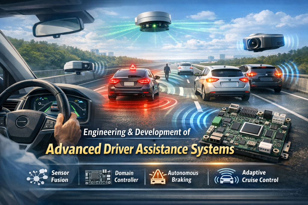
With over a decade of hands-on experience in automotive engineering and L2+ autonomous driving development, my team at Dowway Vehicle and I have navigated the complex transition from basic driver aids to highly sophisticated systems. This technical guide breaks down the engineering realities, system architectures, and calibration methods required to mass-produce today’s core ADAS functions.
- Introduction
- Core Functions of Advanced Driver Assistance Systems
- System Architecture for ADAS Mass Production
- The Engineering Development Process
- Overcoming Key Technical Challenges
- Mass Production Case Study: L2+ ADAS Implementation
- Future Trends
- Frequently Asked Questions about Advanced Driver Assistance Systems (ADAS)
Introduction
Car technology is moving rapidly toward L2+ automation and beyond. The functional matrix of Advanced Driver Assistance Systems (ADAS) continues to expand. While Lane Keeping Assist Systems (LKAS) and Automated Parking Assist (APA) laid the groundwork, the industry has shifted focus to highly complex, real-world driving scenarios. Today, core mass-production configurations include Adaptive Cruise Control (ACC), Autonomous Emergency Braking (AEB), Traffic Jam Assist (TJA), Lane Departure Warning (LDW), and Lane Change Assist (LCA).
This guide examines the system architecture, hardware selection, algorithm development, and real-vehicle calibration required to bring these systems to mass production.
Core Functions of Advanced Driver Assistance Systems
Based on standards like ISO 21448 (SOTIF) and GB/T 39222-2020, these five core ADAS functions form a comprehensive driving safety shield.
Adaptive Cruise Control (ACC)
ACC automatically controls the vehicle’s powertrain and braking to maintain a set speed and a safe following distance based on the vehicle ahead. It is highly suited for highways and clear urban roads, reducing driver fatigue during continuous driving.
- Operating Range: 0-130 km/h (Low-speed ACC covers 0-30 km/h for urban congestion).
- Key Performance Indicators (KPIs): 3-5 distance regulation levels, following response time ≤ 0.5s, speed control accuracy ±1 km/h, and reliability of ≥ 50 continuous stop-start cycles without failure.
Autonomous Emergency Braking (AEB)
AEB relies on multi-sensor fusion to detect forward obstacles (vehicles, pedestrians, cyclists). It automatically triggers the braking system to mitigate or avoid collisions if the driver fails to take immediate action.
- Operating Scenarios: Covers low-speed (≤ 50 km/h) sudden obstacles and high-speed emergency braking.
- KPIs: Collision warning time ≥ 1.5s, braking response time ≤ 0.3s, collision avoidance at speeds ≤ 40 km/h (for pedestrians), and a collision speed reduction rate of ≥ 30% (for vehicles).
Traffic Jam Assist (TJA)
An extension of ACC, TJA manages stop-and-go traffic (≤ 30 km/h) by automatically controlling following distance, starting/stopping, and minor steering corrections, offering semi-autonomous driving in dense traffic.
- KPIs: Following distance accuracy ±5 cm, smooth stop-start transitions (no jolting), steering correction angle ≤ 5°/s, and an activation success rate of ≥ 95%.
Lane Departure Warning (LDW)
LDW uses cameras to monitor lane markings, issuing acoustic or haptic warnings (steering wheel or seat vibrations) if the vehicle drifts without a turn signal.
- Operating Range: ≥ 60 km/h (some models activate as low as 40 km/h).
- KPIs: Lane recognition accuracy ≥ 98% (normal weather) and ≥ 95% (nighttime with sufficient streetlights), warning response time ≤ 0.2s, and a false warning rate ≤ 1 time/100 km.
Lane Change Assist (LCA)
LCA utilizes millimeter-wave (MMW) radar to monitor blind spots. It warns the driver via side-mirror indicators or vibrations if a lane change is initiated while a vehicle is dangerously close in the adjacent lane.
- KPIs: Blind spot detection range 3-5m, recognition accuracy ≥ 97%, warning response time ≤ 0.2s, and a false warning rate ≤ 0.5 times/100 km.
System Architecture for ADAS Mass Production
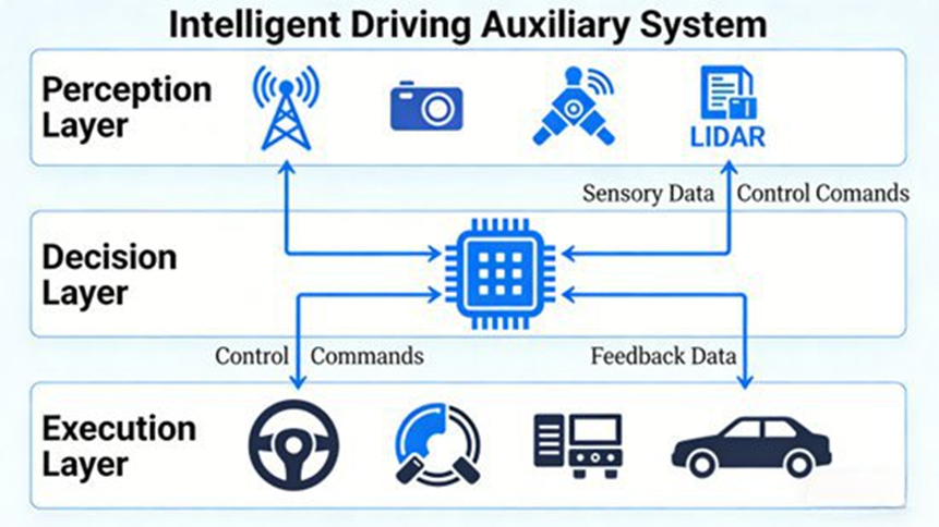
These functions operate on a strict “Perception-Decision-Execution” architecture. We use a “Domain Controller + Multi-Sensor Fusion” approach to ensure real-time reliability and compliance with ISO 26262 (Functional Safety) and ISO 21448 (SOTIF).
Perception Layer: Multi-Sensor Fusion
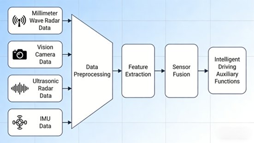
Mass production at a reasonable cost relies on fusing data to remove single-sensor errors, typically using Adaptive Kalman Filter algorithms.
- Millimeter-Wave (MMW) Radar: Core for ACC, AEB, and LCA. Detects distance, speed, and azimuth (0.5-200m). 77GHz is strongly recommended over 24GHz for better accuracy in high-speed and harsh weather (rain, snow, fog) scenarios.
- HD Cameras: Core for LDW, TJA, and AEB (pedestrian/cyclist detection). Requires ≥ 1280×720 resolution, ≥ 30fps, strong light suppression, and night-enhancement to offset radar limitations on non-rigid targets.
- Ultrasonic Radar: 4 front and 4 rear sensors assist AEB and TJA in detecting near-field obstacles (0.1-5m) at low speeds.
- IMU (Inertial Measurement Unit): Works with GPS/Beidou to track vehicle acceleration, yaw rate, and posture with a positioning error of ≤ 1m.
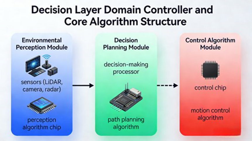
Decision Layer: Domain Controllers and Algorithms
The ADAS Domain Controller acts as the central brain, integrating CPU, GPU, and FPGA chips. It requires an ISO 26262 ASIL-B rating (ASIL-C for certain AEB functions), a main frequency ≥ 1.5GHz, memory ≥ 4GB, and CAN/LIN/Ethernet support. Total response time must be ≤ 100ms.
- Perception Algorithms: Deep learning frameworks (e.g., YOLOv5, CNN) for accurate target recognition.
- Decision Planning: Evaluates speed, distance, and trajectories based on traffic rules.
- Control Algorithms: PID (Proportional-Integral-Derivative) control is utilized for precise, smooth mechanical execution.
Execution Layer: Vehicle Control Interfaces
- Powertrain: Interfaces with the engine ECU/motor controllers for ACC/TJA acceleration (interface response ≤ 50ms).
- Braking: Interfaces with ABS/ESP for AEB, capable of applying ≥ 80% maximum braking force during emergencies.
- Steering: Interfaces with EPS for TJA minor corrections (steering angle control accuracy ≤ 0.5°).
The Engineering Development Process
From concept to delivery, ADAS engineering resolves four main hurdles through a rigorous process:
- Requirements Definition: Establish boundaries, activation/deactivation conditions, and safety goals per GB 7258-2017 standards.
- Hardware Selection: Select established mass-production suppliers (e.g., Bosch/Continental for radar, Sunny/O-Film for cameras, Horizon/Huawei for domain controllers).
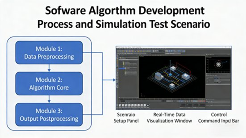
- Software Algorithm Development: Ensure algorithms operate within strict time limits (perception ≤ 50ms, decision ≤ 30ms) using simulation tools like Prescan and Carsim to improve reliability.
- Real-Vehicle Calibration: Adjust sensor mounting angles (correcting camera lens distortion and radar angles) and fine-tune PID parameters across various road conditions.
- Testing & Validation: Conduct functional and performance testing across real-world scenarios to ensure safety protocols activate successfully during sensor or instruction failures.
Overcoming Key Technical Challenges
- Perception Inaccuracies in Complex Scenarios: Rain, night, and glare can blind sensors. Solutions include using 77GHz radars, redundant sensor designs, and Adaptive Kalman filtering to dynamically adjust sensor weights based on real-time environmental conditions.
- Algorithm Reliability: Edge cases (continuous sharp curves, sudden pedestrians) cause failures. Solutions involve expanding training datasets with real and simulated data, and establishing strict operational boundaries that automatically disengage functions safely when limits are breached.
- Calibration Efficiency: Manual calibration takes 1-2 months. Transitioning to automated OBD-based (On-Board Diagnostics) calibration tools reduces this cycle to 2-3 weeks, establishing standardized parameter templates for batch production.
- Functional Safety (SOTIF): Implement redundant hardware architectures (dual controllers/sensors) and OTA (Over-The-Air) update capabilities to continuously refine algorithms based on post-launch data collection.
Mass Production Case Study: L2+ ADAS Implementation
At Dowway Vehicle, we recently developed an L2+ suite for a compact family sedan, designed to improve driving safety and reduce driver fatigue.
Hardware Architecture
- Domain Controller: Horizon Journey 3 chip (1.5GHz, 4GB, ASIL-B compliant).
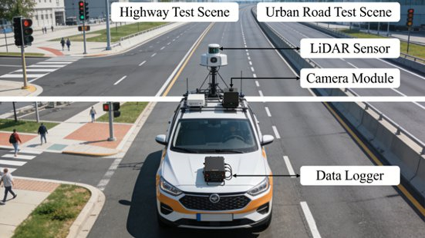
- Sensors: Bosch MRR3 (77GHz front radar), Sunny 1080P front camera, 4x Continental ARS408 (24GHz corner radars), 8x Bosch ultrasonic sensors, and Bosch BMI088 IMU.
- Execution Interfaces: Fully adapted with EPS, ABS/ESP, and a 1.5T engine ECU.
Resolving Real-World Bottlenecks
- AEB Pedestrian Detection in Rain: We optimized the fusion algorithm to assign more weight to MMW radar data and enhanced the camera’s rain-image processing algorithms. Through extensive real-world data training, pedestrian recognition in the rain jumped from 88% to 97%.
- TJA Stop-and-Go Jolting: By adopting a progressive acceleration/deceleration strategy and retuning the PID parameters with the powertrain team, we improved the stop-start smoothness score from 3.2 to 4.5 (out of 5).
Real-Vehicle Validation Results
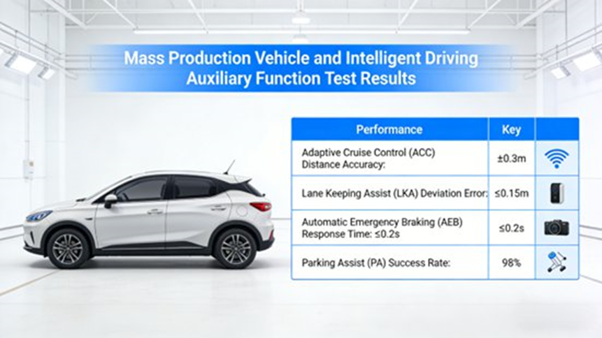
After 3 months of rigorous road testing across urban, highway, and rural environments under various weather conditions, the mass-produced model achieved:
- ACC speed control accuracy: ±1 km/h
- AEB collision speed reduction: ≥ 35%
- LDW false warning rate: 0.8 times/100 km
- LCA recognition accuracy: 98%
The vehicle successfully entered mass production, achieving a 92% user satisfaction rate for these core functions, proving the viability of our engineering solutions.
Future Trends
As we look toward L3+ and beyond, the development of non-LKAS/APA functions will focus on three main pillars:
- Upgraded Sensor Fusion: Integrating LiDAR to dramatically increase 3D perception in complex scenarios.
- Intelligent Algorithms: Incorporating AI Large Models for human-like environment recognition and personalized decision planning.
- Synergistic Ecosystems: Integrating ADAS with high-definition maps and navigation systems for full-scenario urban autonomous driving.
Frequently Asked Questions about Advanced Driver Assistance Systems (ADAS)
1. What are Advanced Driver Assistance Systems (ADAS)?
Short Answer: They are electronic vehicle systems designed to help the driver and improve overall road safety.
Advanced Driver Assistance Systems (ADAS) monitor the driving environment and support vehicle control. The main purpose is to reduce human error and prevent accidents by providing warnings or automatically controlling braking, acceleration, or steering when necessary. Typical functions include Adaptive Cruise Control (ACC), Autonomous Emergency Braking (AEB), Lane Departure Warning (LDW), Blind Spot Detection (BSD), and Traffic Sign Recognition (TSR).
2. How do ADAS systems work?
Short Answer: They work through a continuous three-step process: perception, decision, and execution.
First, the Perception Layer uses sensors (cameras, radar, LiDAR, and ultrasonic) to collect real-time environmental data. Next, the Decision Layer uses processors and algorithms to analyze this data, detect hazards, and evaluate collision risks. Finally, the Execution Layer mechanically performs actions such as braking, accelerating, steering, or issuing driver warnings. To ensure accuracy, multiple sensors are combined through “sensor fusion,” which integrates different types of data to create a clear view of the vehicle’s surroundings.
3. Are ADAS systems the same as autonomous driving?
Short Answer: No. ADAS requires an active human driver, whereas fully autonomous driving does not.
ADAS primarily operates within SAE (Society of Automotive Engineers) automation Levels 0 to 3. In these levels, the driver must still supervise the vehicle and remains legally responsible for driving. ADAS automates specific tasks (like speed control or braking), but autonomous driving (Levels 4 and 5) means the vehicle system controls all driving tasks independently without human intervention.
4. What sensors are commonly used in ADAS?
Short Answer: The four most common sensors are cameras, millimeter-wave radar, LiDAR, and ultrasonic sensors.
- Cameras: Essential for detecting lane markings, traffic signs, and pedestrians.
- Radar (Millimeter-Wave): Measures the precise distance and speed of nearby vehicles.
- LiDAR: Emits light pulses to provide precise, high-resolution 3D environmental mapping.
- Ultrasonic Sensors: Detect close-range obstacles, primarily used for parking.
5. What are the limitations of ADAS?
Short Answer: They can struggle with severe weather, blind spots, unpredictable events, and driver over-reliance.
Current ADAS technologies face several limitations. Sensor performance can drop during heavy rain, thick fog, snow, or extreme low-lighting conditions. Sensors also have specific detection angles, meaning they cannot cover every single blind spot around the vehicle. Highly unpredictable environments, like sudden pedestrian crossings, can still cause false warnings. Finally, the biggest risk is human error—when drivers mistakenly assume the vehicle can drive itself and stop paying attention to the road.
