


< Back to Automotive Simulation Toolchain
Author: Johnny Liu, CEO at Dowway Vehicle
Last Updated: March 12, 2026
Article Type: Cluster page
Audience: Automotive CAE engineers, durability teams, simulation specialists, and vehicle development managers
- Direct Answer
- TL;DR
- Why this matters
- Why Is Fatigue Analysis Critical in Automotive Engineering?
- What Is MxSim.Fatigue and Where Does It Fit in the Automotive Toolchain?
- How Does MxSim.Fatigue Work? Core Technical Principles
- What Fatigue Life Models Does MxSim.Fatigue Support?
- Why Is Load Spectrum Processing So Important in Automotive Fatigue Analysis?
- What Are the Core Functions of MxSim.Fatigue in Real Automotive Projects?
- Step-by-Step Example: Chassis Control Arm Fatigue Analysis
- Real Automotive Applications of MxSim.Fatigue
- Case 1 — Vehicle Body Weld Fatigue Analysis and Optimization
- Case 2 — Chassis Control Arm Failure Analysis and Test Correlation Improvement
- Case 3 — Engine Crankshaft Fatigue Life Prediction
- What Makes MxSim.Fatigue Valuable for the Automotive Industry?
- How Does MxSim.Fatigue Support Lightweight and Electric Vehicle Development?
- What Is the Future of Automotive Fatigue Analysis Software?
- Final Takeaway
- Top 5 Frequently Asked Questions About MxSim.Fatigue in Automotive Engineering
- 1. What is MxSim.Fatigue, and what role does it play in automotive simulation workflows?
- 2. What fatigue analysis methods are supported by MxSim.Fatigue?
- 3. How does MxSim.Fatigue handle automotive load spectra?
- 4. What advantages does MxSim.Fatigue provide compared with traditional fatigue testing?
- 5. What are the typical automotive applications of MxSim.Fatigue?
- Author Bio
- Editorial Note
- Source Notes
Direct Answer
MxSim.Fatigue is fatigue analysis software used in automotive engineering to predict structural damage, estimate service life, and improve durability before physical testing begins. In real vehicle development, it links FEA stress-strain results with fatigue models, load spectrum processing, result plots, and structural optimization for body structures, chassis parts, powertrain components, and EV systems. (mxcae.com)
TL;DR
- Vehicle parts often fail from repeated cyclic loads rather than one overload event. (mathworks.com)
- MxSim.Fatigue is used to process load spectra, calculate fatigue damage, predict life, and support design changes. (mxcae.com)
- It is useful for body welds, chassis suspension parts, crankshafts, and EV structural components.
- The source report connects it with lower testing cost, shorter development cycles, and better durability performance.
- This version is written to be easier for Google and LLM systems to read, quote, and summarize.
Why this matters
Automotive teams are asked to build lighter vehicles, keep durability high, and move faster. That creates pressure early in development. If a fatigue problem is found late, the cost rises quickly because redesign, test repeats, and schedule delays often follow. Fatigue analysis software helps teams spot risk earlier and act before those problems spread through the program.
Why Is Fatigue Analysis Critical in Automotive Engineering?
Fatigue analysis matters because most automotive components work under repeated load cycles for years. Road irregularities, engine vibration, steering input, braking force, and thermal effects all add stress over time. That repeated loading can create damage, start cracks, and shorten service life even when the part looks safe under a simple strength check. (mathworks.com)
This is why static strength alone is not enough. A control arm, weld, or crankshaft fillet may survive one heavy event and still fail early after many smaller cycles.
What causes fatigue failure in vehicle components?
The source report points to several common fatigue drivers in automotive use:
- alternating stress from road roughness
- periodic loads from engine vibration
- dynamic loads during braking and steering
- random and shock loads during real driving
- coupled thermal and mechanical loading in some areas
These loads act again and again. Over time, damage builds until the structure can no longer carry the load safely.
Why are traditional road tests and bench tests not enough on their own?
The source report identifies three main limits:
- They take time
Road tests and bench tests are slow to plan, run, and repeat. - They cost a lot
Prototypes, fixtures, instrumentation, and test time are expensive. - They may miss real service loads
A test setup may not fully match what the vehicle sees in the field.
That last point is a big one. A part can pass the lab test and still fail on the road if the duty cycle does not match real use.
What Is MxSim.Fatigue and Where Does It Fit in the Automotive Toolchain?
MxSim.Fatigue is described in the supplied report as a core fatigue module in the MxSim CAE toolchain. Its job is to turn structural analysis results into fatigue life predictions, damage maps, and design guidance for real automotive parts. Public product pages also describe it as a fatigue life analysis solution for high-cycle fatigue, low-cycle fatigue, weld fatigue, spot-weld fatigue, random vibration fatigue, frequency-domain fatigue, and crack fatigue analysis. (mxcae.com)
In a typical engineering workflow, it sits after structural analysis and before optimization:
- CAD modeling
- Finite element analysis
- Fatigue life prediction with MxSim.Fatigue
- Structural optimization and iteration
That makes it a strong cluster-page topic because it focuses on one task in the larger CAE workflow rather than covering the whole simulation stack.
Why is it useful for automotive teams?
The source report says MxSim.Fatigue is useful because it supports:
- Chinese interface and report output
- common CAD and solver file formats
- large multi-condition simulations
- body, chassis, and powertrain workflows
- welds, spot welds, springs, and bolts
- integration with optimization tools
The report also states that it has been used in more than 20 vehicle programs and over 1,000 engineering cases. I am treating those numbers as report-based claims.
Which vehicle systems can it analyze?
Based on the report and public product descriptions, the main automotive uses include:
- body-in-white structures
- body welds and spot welds
- chassis and suspension parts
- powertrain and rotating components
- battery pack structures
- electric motor-related structural parts
Public product pages also mention battery pack random vibration fatigue. (mxcae.com)
How Does MxSim.Fatigue Work? Core Technical Principles
MxSim.Fatigue follows a clear engineering path: load interpretation, stress or strain calculation, fatigue damage accumulation, life prediction, and structural optimization. This matches how fatigue software is commonly used in CAE work. Different methods are selected based on the part, the loading mode, and the type of failure expected. (simulatemore.mscsoftware.com)
The supplied report builds this process around automotive use cases, which makes the workflow easier to apply in real vehicle programs.
Finite element basis and large-scale structural analysis
The report says MxSim.Fatigue relies on finite element analysis to divide complex structures into connected elements and calculate local stress and strain under service loading. It also says the software is built on the MxSim.Mechanical kernel, with a full element library, material constitutive models, structural analysis functions, and efficient solver mathematics for large multi-part assemblies.
That matters because fatigue cracks often start at local hot spots such as:
- weld toes
- fillets
- ball-joint transitions
- shaft shoulders
- local geometry changes
Why multi-physics coupling matters
The source report says fatigue is often affected by more than one physical field. In automotive parts, stress can interact with:
- temperature
- vibration
- dynamic motion
- preload and installation condition
The report adds that MxSim.Fatigue can connect with thermal and vibration modules in the MxSim family so these effects can be combined during analysis. This is useful for engine-side parts, rotating systems, and newer EV structures where thermal and structural loads may act together.
What Fatigue Life Models Does MxSim.Fatigue Support?
MxSim.Fatigue supports several fatigue methods so it can fit different automotive scenarios. The source report covers three core method groups, and public product pages support that broader method coverage. (mxcae.com)
1. Stress-Life Method (S-N Curve)
The S-N method is used mainly for high-cycle fatigue. It estimates fatigue life from the relationship between stress amplitude and number of cycles to failure. This is a common method for elastic, high-cycle problems. (ansyshelp.ansys.com)
The source report recommends it for:
- vehicle body structures
- frames
- structural members under repeated loading
- chassis parts such as control arms
This method is also used in the body weld case and the control arm workflow in the report.
2. Miner’s Rule for cumulative damage
The source report uses Miner’s rule to calculate cumulative fatigue damage under variable-amplitude loading. Each stress level uses up part of the part’s available life. When the summed damage reaches the failure limit, fatigue failure is predicted. Rainflow-based fatigue workflows often use this type of damage accumulation logic. (mathworks.com)
The report gives this standard form:
[
\sum_{i=1}^{n}\frac{n_i}{N_i}=1
]
Where:
- (n_i) = actual cycles at stress level (i)
- (N_i) = fatigue life at stress level (i)
This fits automotive load histories well because vehicles see many stress levels during real service, not one constant amplitude.
3. Strain-Life Method (Local Stress-Strain / ε-N)
The source report describes a local stress-strain method for low-cycle fatigue and local plastic deformation. This is the right type of method when purely elastic treatment is not enough. (ansyshelp.ansys.com)
The report points to these uses:
- engine blocks
- crankshafts
- high-stress local regions
- parts with fatigue crack initiation driven by local strain concentration
4. Fracture Mechanics Method
The report also includes a fracture mechanics method for parts that already contain cracks or crack-like flaws. This method is used to estimate remaining life based on crack-tip behavior and crack growth. It is useful when the engineering question is not just when a crack starts, but how fast it grows and how much life is left. (simulatemore.mscsoftware.com)
Typical automotive examples in the report include:
- brake discs
- rotating shafts
- flaw-sensitive parts
5. Material calibration for automotive materials
The source report also says users can define material data and calibrate fatigue model parameters from test results. That is important in automotive engineering because fatigue behavior changes a lot from one material to another.
The report specifically mentions:
- high-strength steel
- aluminum alloys
- composite materials
It also says engineers can import fatigue test data and build their own material libraries for lightweight vehicle programs.
Why Is Load Spectrum Processing So Important in Automotive Fatigue Analysis?
Load spectrum processing is one of the most important parts of fatigue analysis because the quality of the fatigue result depends on how realistic the loading history is. Vehicle parts rarely see simple constant-amplitude cycles. They see variable loads from roads, steering, braking, vibration, and temperature. Rainflow counting is widely used to turn that history into counted cycles for fatigue damage analysis. (mathworks.com)
The supplied report treats this as a core strength of MxSim.Fatigue and says it supports:
- measured load spectrum import
- simulation-generated load spectra
- load editing
- load compression
- random loads
- shock loads
- periodic loads
What data formats can it use?
The source report says MxSim.Fatigue supports:
- ASCII
- CSV
- MTS
It also says the software can read test data collected from road tests and bench rigs, including load-time curves and stress-time histories.
How does it process load spectra?
The report specifically mentions:
- rainflow counting
- equivalent-damage-based compression
- load editing
- redefinition of test conditions through road spectrum analysis
Rainflow counting is a standard method for cycle extraction from time histories. ASTM and MathWorks references support that general engineering use. (astm.org)
Why does this matter in durability programs?
Because a bench test may not match real road service. The control arm case in the source report shows this clearly: the lab setup missed a torsional load component, and that mismatch allowed a real-world failure to slip through.
What Are the Core Functions of MxSim.Fatigue in Real Automotive Projects?
MxSim.Fatigue is described as a full engineering workflow rather than a single solver feature. The report covers model import, preprocessing, load definition, material setup, solving, postprocessing, and optimization. Public product descriptions support that same workflow view. (mxcae.com)
Multi-format model import and preprocessing
The source report says users can import automotive models using:
- STEP
- IGES
- STL
- bdf
- cbd
- fem
- inp
It also says models from MxSim, Abaqus, and related environments can be imported without rebuilding everything from scratch.
After import, the workflow includes:
- geometry simplification
- mesh generation
- mesh quality control
- boundary condition setup
This is especially important for body shell structures, chassis joints, and large assemblies.
Support for engineering connection elements
The report says the module supports:
- spot welds
- weld seams
- springs
- bolts
That matters because many fatigue failures start in connection regions rather than smooth sections of the structure.
Load and material parameter setup
The source report lists three main load categories:
Static loads
- self-weight
- assembly preload
Dynamic loads
- engine vibration
- road excitation
Thermal loads
- high-temperature loading around engine-side parts
For materials, the report says the module includes common automotive materials such as:
- Q235 steel
- 6061 aluminum alloy
- high-strength steel
It also says users can import fatigue test data from:
- rotating bending tests
- axial tension-compression tests
- torsion fatigue tests
This allows users to build custom material libraries for new projects.
Fatigue solving and postprocessing
The report says engineers can choose the fatigue method based on whether the part sees high-cycle or low-cycle loading, then set solution parameters such as cycle count and convergence precision. Large jobs can run with parallel computation to save time.
For results, the module can generate:
- fatigue life contour plots
- damage accumulation contour plots
- stress distribution contour plots
- detailed reports with life, damage, stress, and strain data
These results help engineering teams see where the weak point is and why it appears.
Structural optimization and iterative design
The source report says MxSim.Fatigue can connect with MxSim optimization tools so engineers can change:
- wall thickness
- fillet radius
- rib layout
- local reinforcement
Then they can re-run the model and check whether the new design meets the fatigue target while still keeping weight under control.
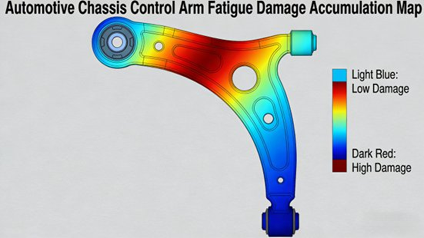
Step-by-Step Example: Chassis Control Arm Fatigue Analysis
The control arm workflow in the source report is one of the most practical parts of the article because it shows how the software is used from model import through design change.
Step 1 — Import and preprocess the CAD model
Import the chassis control arm CAD model in STEP format. Remove small features such as tiny holes and small chamfers that do not change the main load path but make the model harder to solve. Then create a tetrahedral mesh with a 2 mm mesh size, check that the mesh distortion rate is 5% or less, and set boundary conditions by fixing the frame-side connection so it matches the real installed state.
Step 2 — Define material properties
Use the built-in high-strength steel material definition and import the correct S-N curve from rotating bending fatigue testing. Set:
- elastic modulus
- Poisson’s ratio
- fatigue limit
Step 3 — Apply the measured load spectrum
Import the measured load spectrum from full-vehicle road testing. The report says it includes:
- vertical load history
- lateral load history
Use rainflow counting to compress the signal while keeping the key fatigue cycles. Then apply the load to the ball-joint connection of the control arm. (mathworks.com)
Step 4 — Run fatigue solving
Select:
- S-N total-life method
- Miner’s rule
Then set the fatigue solution target to 10^7 cycles and run the job in parallel.
Step 5 — Review fatigue results
Check the:
- fatigue life contour map
- damage accumulation contour map
The source report says the weak area is the fillet near the ball-joint connection. Record the fatigue life and maximum local stress in the report output.
Step 6 — Optimize and iterate
Increase the fillet radius from R3 mm to R5 mm, then run the model again and verify that the part now meets the design target of at least 10^6 cycles.
Real Automotive Applications of MxSim.Fatigue
The source report includes three main automotive cases. Together, they cover body, chassis, and powertrain applications and show how the software is used in practical durability work.
Case 1 — Vehicle Body Weld Fatigue Analysis and Optimization
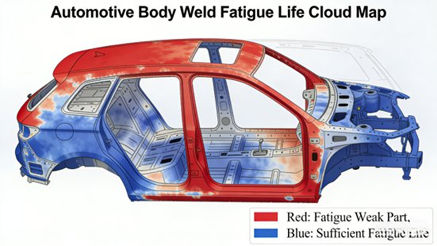
Body welds are common fatigue hot spots because load transfer and geometry changes create local stress concentration. Public MxSim product pages also mention weld and spot-weld fatigue as supported applications. (mxcae.com)
Problem
The report says body weld durability often requires repeated physical test loops, which adds time and cost.
Application setup
The engineering team imported the body FE model and focused on the weld region between the door and the body frame. The setup used:
- high-strength steel material data
- road-test load spectra
- bending loads
- torsional loads
- S-N method
- Miner’s rule
Result
The report states that the weld corner had a fatigue life of only 8 × 10^5 cycles, below the design target of 1 × 10^6 cycles, which created a clear crack risk.
Optimization
The optimization plan in the report included:
- increasing weld height from 5 mm to 8 mm
- improving the weld transition radius
- reducing local stress concentration
Outcome
After the new simulation, the report says the critical weld region improved to 1.5 × 10^6 cycles, which met the design target. It also states that the updated process cut development cycle time by 30% and reduced test cost by 25%.
Case 2 — Chassis Control Arm Failure Analysis and Test Correlation Improvement
This case matters because it shows how fatigue simulation can also expose a test-method problem, not just a part problem.
Problem
The source report says a chassis control arm cracked after about 5,000 km of strengthened road durability testing even though the bench durability test had passed.
Application setup
The team imported the control arm model, meshed it, assigned materials and boundary conditions, and compared:
- road-test load spectra
- bench-test load spectra
Key finding
The simulation showed that the bench test did not reproduce the torsional load component seen in actual road use. Because of that, the ball-joint connection region built up damage in the vehicle even though the bench test looked acceptable.
Improvement
The report says the team responded by:
- redefining the bench load spectrum
- adding the missing torsional component
- improving the ball-joint connection structure
- adding reinforcement ribs to reduce local stress concentration
Outcome
The report says the improved design passed both bench and road durability testing, and fatigue life increased to 2 × 10^6 cycles.
Case 3 — Engine Crankshaft Fatigue Life Prediction
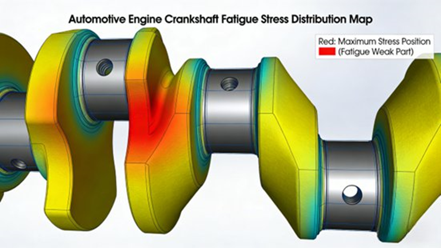
Crankshafts are classic durability-critical parts because they see gas pressure and inertia loads during repeated engine operation. The source report treats this as a mixed fatigue problem and uses a local stress-strain approach. (ansyshelp.ansys.com)
Application setup
The source report says the crankshaft FE model used:
- local stress-strain method
- ductile iron material data
- cyclic stress-strain curve
- load histories from gas pressure and inertial force
Result
The weak area was the transition fillet between the connecting-rod journal and the crank arm, where predicted fatigue life was 1.2 × 10^6 cycles, close to the design limit.
Optimization
The report gives two main changes:
- increase fillet radius from R2 mm to R4 mm
- apply shot peening to improve surface compressive residual stress and reduce effective stress concentration
Outcome
The report says fatigue life improved to 2.5 × 10^6 cycles, which met the engine target of 10 years / 200,000 km.
What Makes MxSim.Fatigue Valuable for the Automotive Industry?
MxSim.Fatigue is useful because it combines fatigue theory with a workflow that fits real vehicle development. The report groups its value into technical strengths and business gains, while public product pages support its use across high-cycle, low-cycle, weld, crack, and vibration fatigue work. (mxcae.com)
Main technical advantages
Chinese-language support
The report says the software has a full Chinese interface and Chinese report output that fit domestic engineering teams.
High simulation accuracy
The source report says fatigue life prediction error can be within 10% in proper engineering use. I am presenting that as a report-based claim.
Automotive fit
The workflow is built around body, chassis, and powertrain use cases.
Strong compatibility and efficiency
The report highlights support for many file formats, large multi-condition jobs, parallel solving, and remote compute scheduling.
Main business value
Shorter development cycles
The report estimates that moving fatigue work into the design phase can reduce development time by 30% to 50%.
Lower development cost
It says one component fatigue simulation may cost about one-tenth of full physical validation.
Better reliability
Weak points can be found and fixed before field failures appear.
Support for lightweighting and EV development
The report directly links MxSim.Fatigue to high-strength steel, aluminum alloys, composites, EV battery packs, motors, and other next-generation vehicle parts.
How Does MxSim.Fatigue Support Lightweight and Electric Vehicle Development?
Fatigue analysis becomes even more important when a team is reducing mass. Lighter structures can lose durability margin if geometry, material behavior, and load paths are not checked carefully. Recent automotive fatigue and load-spectrum work still treats this as a key part of vehicle durability engineering. (saemobilus.sae.org)
The source report says MxSim.Fatigue supports fatigue analysis for:
- high-strength steel
- aluminum alloy
- composite materials
It also says the module can support newer vehicle applications such as:
- battery pack durability analysis
- electric motor structural fatigue
- EV component vibration fatigue
- future smart-vehicle structural parts
Public product pages also mention battery pack random vibration fatigue. (ruanfujia.com)
What Is the Future of Automotive Fatigue Analysis Software?
The final section of the source report points to two main directions.
First, it expects stronger use of AI and big-data methods for smarter load spectrum prediction and adaptive calibration of fatigue models. That makes sense because one of the hardest parts of durability work is building a load history that really matches field use.
Second, it expects broader use in new-energy and intelligent vehicle systems, including battery packs, motors, and autonomous-driving-related structures. The general move toward digital engineering and multi-domain simulation supports that direction. (saemobilus.sae.org)
Final Takeaway
MxSim.Fatigue is best understood as automotive fatigue analysis software that turns real load histories into design decisions. Based on your supplied report, it is more than a postprocessing tool. It covers model import, FEA-linked fatigue evaluation, load spectrum handling, damage prediction, result visualization, and structural optimization for body, chassis, and powertrain applications.
That is why it matters in modern vehicle development. It helps engineering teams find weak points earlier, reduce repeated test loops, improve test correlation, and support lightweight, long-life design. It also gives the software a strong place in EV development, where battery packs, motor housings, and new structural layouts create fresh durability challenges.
Top 5 Frequently Asked Questions About MxSim.Fatigue in Automotive Engineering
1. What is MxSim.Fatigue, and what role does it play in automotive simulation workflows?
Short answer: MxSim.Fatigue is the fatigue life prediction step in the automotive CAE workflow.
MxSim.Fatigue is a fatigue and durability simulation module in the MxSim CAE ecosystem. It is used to predict fatigue damage and service life by taking stress-strain results from finite element analysis and applying fatigue life models. Public product pages describe it as a one-stop fatigue life analysis solution, and the supplied report places it after structural analysis and before design optimization. (mxcae.com)
In automotive engineering, it usually appears in this sequence:
- CAD modeling
- Finite element analysis
- Fatigue life prediction with MxSim.Fatigue
- Structural optimization
The source report says it is widely used for:
- vehicle body structures
- chassis suspension arms
- welded joints and spot welds
- engine crankshafts
- battery pack structures
Using fatigue simulation early helps engineers find weak points before full prototype builds, which can reduce cost and save time.
2. What fatigue analysis methods are supported by MxSim.Fatigue?
Short answer: It supports stress-life, strain-life, and crack-based fatigue methods.
MxSim.Fatigue supports several fatigue life prediction approaches so engineers can match the method to the failure mode. The source report covers the three main groups below, and public product pages also describe support for high-cycle fatigue, low-cycle fatigue, weld fatigue, and crack-related analysis. (mxcae.com)
Stress-Life Method (S-N Curve)
- used for high-cycle fatigue
- based on material S-N curves
- often paired with Miner’s rule
- common for vehicle frames, body structures, and chassis parts
Strain-Life Method (ε-N / local stress-strain)
- used for low-cycle fatigue
- includes local plastic deformation effects
- common for engine components and crankshafts
Fracture Mechanics Method
- used for crack growth and remaining life
- based on crack-tip behavior and crack propagation
- common for brake discs, rotating shafts, and crack-sensitive joints
Together, these methods help engineers assess both crack initiation and crack growth under real vehicle service loads. (ansyshelp.ansys.com)
3. How does MxSim.Fatigue handle automotive load spectra?
Short answer: It imports real load histories, counts cycles, compresses data, and keeps the damage-driving content.
Load spectrum processing is a key part of fatigue analysis because vehicle components see variable-amplitude loading, not simple constant cycles. The source report says MxSim.Fatigue supports measured road-load data, bench durability data, and simulation-generated loads. It also says the module supports spectrum editing, compression, and rainflow counting for cycle extraction. (mathworks.com)
The report lists these typical load sources:
- road test data
- bench durability test data
- simulation-generated load data
It also lists these processing functions:
- rainflow counting
- load spectrum editing
- load spectrum compression
- damage-equivalent handling
Typical automotive load cases include:
- road irregularity loads
- engine vibration loads
- braking and steering loads
- thermal loads near engines or batteries
4. What advantages does MxSim.Fatigue provide compared with traditional fatigue testing?
Short answer: It helps teams test earlier in the design process, spend less, and find weak points sooner.
Traditional durability verification depends on road testing and bench testing, both of which take time and cost money. The source report says fatigue simulation gives teams a faster and less expensive way to assess life during design. Broader fatigue-analysis references support that workflow value as well. (simulatemore.mscsoftware.com)
Reduced development time
Fatigue performance can be checked earlier, which lowers the need for repeated hardware loops.
Lower testing cost
Simulation reduces the need for:
- repeated prototype manufacturing
- repeated road durability tests
- repeated instrumentation and setup
Earlier weak-point detection
The report says MxSim.Fatigue can generate:
- fatigue life contour plots
- damage accumulation maps
- stress distribution plots
These make it easier to spot fatigue-critical regions early.
Direct link to optimization
Simulation results can be used for:
- geometry changes
- wall-thickness adjustment
- fillet-radius changes
- rib and reinforcement layout
5. What are the typical automotive applications of MxSim.Fatigue?
Short answer: It is mainly used for body, chassis, powertrain, and EV durability work.
The supplied report and public product descriptions show that MxSim.Fatigue is used across several vehicle subsystems. (mxcae.com)
Vehicle body
Typical uses include:
- weld fatigue analysis
- body durability validation
- local weld-corner improvement
Chassis components
Examples include:
- control arms
- subframes
- suspension parts
The main focus is:
- stress concentration
- variable-amplitude fatigue damage
- test-spectrum correlation
Powertrain components
Examples include:
- crankshafts
- gears
- transmission shafts
Typical methods may include:
- strain-life analysis
- crack-related assessment
- local geometry changes
Electric vehicle components
With EV development, fatigue simulation is also used for:
- battery pack structural durability
- motor housing fatigue
- inverter cooling structure support parts
- random vibration fatigue in enclosure systems
Author Bio
Johnny Liu is the CEO at Dowway Vehicle and works on vehicle engineering strategy, automotive technology applications, and product development direction. This article is based on the supplied technical report on MxSim.Fatigue and is written for readers working in vehicle durability, CAE, and simulation-led development.
Editorial Note
This article is written as an engineering reference page. It is not a substitute for software-specific training, fatigue testing standards, design approval, or program-level validation work.
Source Notes
This article is based mainly on the technical report you supplied. External references are used to support general fatigue-analysis concepts such as rainflow counting, stress-life methods, strain-life methods, crack-growth logic, and product-level workflow descriptions.
Selected references
- MxSim.Fatigue product pages describing fatigue workflow coverage and application areas. Accessed: March 12, 2026. (mxcae.com)
- MSC fatigue overview on fatigue workflow and crack growth concepts. Accessed: March 12, 2026. (simulatemore.mscsoftware.com)
- MathWorks and ASTM references on rainflow counting and fatigue cycle counting. Accessed: March 12, 2026. (mathworks.com)
Ansys reference on stress-life and strain-life methods. Accessed: March 12, 2026. (ansyshelp.ansys.com)
