

< Back to Platform Development
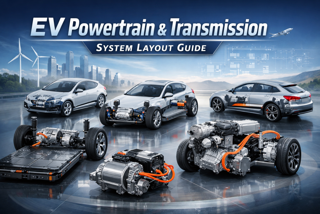
By Johnny Liu, CEO at Dowway Vehicle | Published: March 4, 2026
Author Bio: Johnny Liu leads Dowway Vehicle, building advanced automotive engineering and powertrain system solutions.
- Key Takeaways for Automotive Engineers
- 2.1 Key Powertrain Elements
- 2.2 Five Basic Layout Principles
- 3.1 Front-Mounted Single Motor Layout (FWD)
- 3.2 Rear-Mounted Single Motor Layout (RWD)
- 3.3 Front and Rear Dual Motor Layout (AWD)
- 4.1 Wheel-End Motor Layout
- 4.2 In-Wheel (Hub) Motor Layout
- 5.1 P2 Configuration Layout
- 5.2 P3 Configuration Layout
- 5.3 P4 Configuration Layout
- What is a powertrain layout in a vehicle?
- Why does powertrain layout matter in vehicle design?
- What are the differences between FWD, RWD, and AWD drivetrain layouts?
- How are electric powertrain and transmission systems connected?
Key Takeaways for Automotive Engineers
- Optimal Weight Distribution: Advanced EV powertrain layouts aim for a 1:1 front-to-rear axle load ratio and a low center of gravity (500-600mm) to maximize handling and safety.
- Centralized vs. Distributed: Centralized architectures (FWD, RWD, AWD) dominate mass production. Distributed layouts (Wheel-end and In-wheel motors) represent the future of precise torque vectoring and tight space use.
- High-Level Integration: The industry is moving toward deep “X-in-1” integration (like BYD’s 8-in-1, Nissan’s 14-in-1) and Cell-to-Chassis (CTC) structural batteries to shrink volume by up to 30% and push power density to 4.5kW/kg.
- Hybrid Flexibility: P2, P3, and P4 hybrid configurations bridge the gap between ICE and pure EV, optimizing thermal efficiency and mechanical transmission paths.
1. Introduction to Electric Powertrain Architecture
The car industry is shifting to electric power fast. The powertrain and transmission system layout directly dictates a vehicle’s dynamic performance, space, energy use, and safety.
Compared to older internal combustion engine (ICE) systems, electric powertrains offer simpler structures, rapid throttle response, high energy conversion rates, and zero emissions. But they bring tough engineering hurdles, like tight spaces, uneven weight distribution, and hard thermal management tasks. This guide breaks down the core layout types, technical details, and engineering design rules of modern electric powertrain systems.
2. Core Components and Basic Layout Principles
2.1 Key Powertrain Elements
The layout design must build upon the specific traits and constraints of the core components:
- Drive Motors: The main power output. Mainstream passenger cars mostly use Permanent Magnet Synchronous Motors (PMSM) because of their high efficiency, high power density, and small size. Commercial vehicles often use AC Induction Motors for strong overload capacity and lower costs.
- Power Batteries: The main energy storage, mostly using lithium-ion batteries (like ternary lithium and Lithium Iron Phosphate or LFP).
- Electronic Control Systems: The operational brain, including the Motor Control Unit (MCU), Battery Management System (BMS), and Vehicle Control Unit (VCU). Engineers place these close to the core execution parts to cut down signal interference and line loss.
- Transmission & Auxiliary Components: This group includes reducers, differentials (often built into the electric drive assembly), thermal management systems, and charging systems.
2.2 Five Basic Layout Principles
- Weight Balance: Spread component weight to reach a front-to-rear axle load ratio near 1:1 (for passenger cars), avoiding “nose-heavy” or “tail-heavy” dynamics.
- Space Optimization: Fully use the chassis, engine compartment, and trunk to keep passenger and cargo room open.
- Energy Efficiency: Shorten the transmission path to lower mechanical losses. Keep the distance between the ECU, motor, and battery tight.
- Safety & Reliability: Put batteries in crash-safe zones. Give motors and ECUs strict protection from heat, moisture, and electromagnetic interference. Thorough cooling systems must prevent extreme temperatures.
- Scalability: Leave room in the architecture for future upgrades, fitting different battery capacities and motor power outputs.
3. Centralized Powertrain & Transmission Layouts
Centralized setups pack the drive motor, reducer, and MCU into a single electric drive assembly on the front axle, rear axle, or both. This design is highly compact, cheap to build, and reliable.
3.1 Front-Mounted Single Motor Layout (FWD)
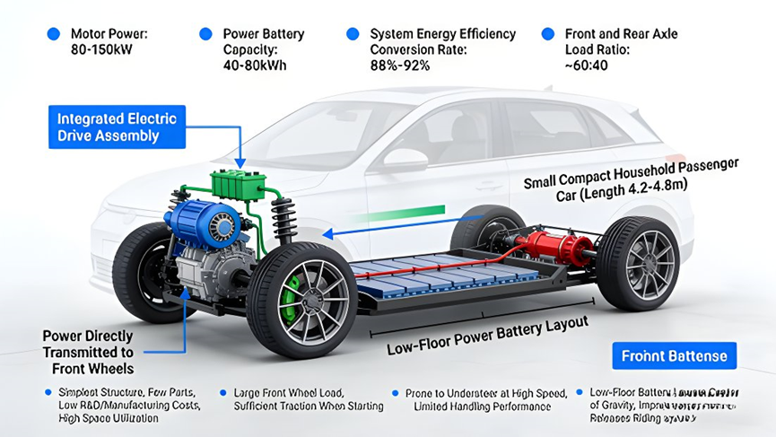
The FWD layout puts the electric drive assembly on the front axle. The battery sits flat beneath the floor (low-floor layout). Power goes straight to the front wheels.
- Engineering Details: Simplest structure, fewest parts, lowest R&D/manufacturing costs, and highest space use. Launch traction is good, but the car might understeer during fast cornering.
- Technical Specs: Motor power 80-150kW, battery capacity 40-80kWh, system efficiency 88%-92%, axle load ratio roughly 60:40.
- Typical Applications: Compact passenger cars measuring 4.2-4.8m (e.g., BYD Dolphin, Tesla Model 3 Standard Range).
3.2 Rear-Mounted Single Motor Layout (RWD)
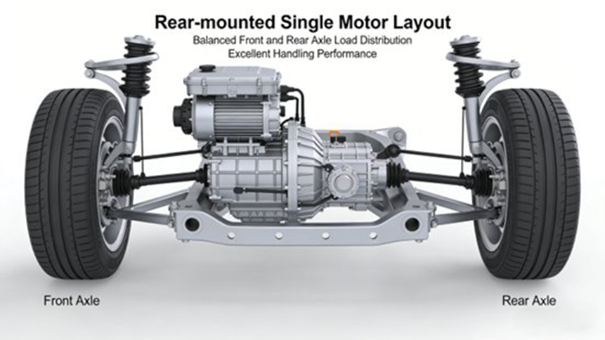
This layout puts the electric drive assembly on the rear axle to drive the rear wheels.
- Engineering Details: Reaches great handling and high-speed cornering stability. The open front compartment can hold thermal management systems. Rear placement needs strict structural design for cooling and NVH (noise, vibration, and harshness) control.
- Technical Specs: Motor power 150-300kW, battery capacity 60-120kWh, system efficiency 90%-93%, axle load ratio roughly 48:52.
- Typical Applications: Mid-to-large passenger cars and high-performance EVs measuring 4.8-5.2m (e.g., Tesla Model S, Porsche Taycan).
3.3 Front and Rear Dual Motor Layout (AWD)
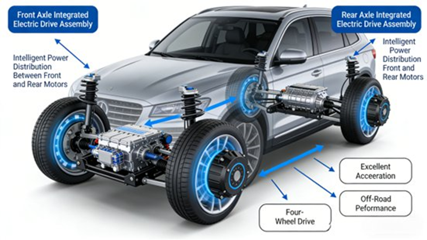
The AWD layout uses two independent electric drive assemblies—one on the front axle and one on the rear—controlled on their own for smart power distribution.
- Engineering Details: Delivers extreme acceleration (0-100km/h in 3-5 seconds) and great passability. Drawbacks include more complexity, heavier curb weight, higher costs, and the need to fix cooperative control to avoid power interference.
- Technical Specs: Total motor power 200-500kW, battery capacity 80-150kWh, system efficiency 89%-92%. Axle load ratio adjusts dynamically (40:60 to 60:40).
- Typical Applications: Mid-to-large vehicles and high-performance SUVs measuring 4.8-5.5m (e.g., Tesla Model Y Performance, BYD Han EV AWD).
4. Distributed Powertrain System Architectures
Distributed architectures drop traditional centralized electric drive assemblies and drive shafts. They offer tight, independent control of each wheel.
4.1 Wheel-End Motor Layout
This layout mounts the drive motor near the wheel, packing it with a reducer and brake to form a wheel-end drive module.
- Engineering Details: Drastically cuts the transmission path, dropping mechanical loss. Allows for tight torque vectoring. Engineers must carefully manage the weight and cooling of these modules to protect suspension performance.
- Technical Specs: Single motor power 50-100kW, battery capacity 80-120kWh, system efficiency 92%-95%.
- Typical Applications: High-end passenger cars and light commercial vehicles measuring 4.9-5.5m (e.g., specific versions of the NIO ES8, Yutong light electric buses).
4.2 In-Wheel (Hub) Motor Layout
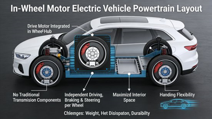
The ultimate distributed form builds the motor right inside the wheel hub. It connects the rotor straight to the wheel and removes all transmission parts.
- Engineering Details: Transmission losses drop to near zero. It frees up chassis space entirely. Yet, it meets tough engineering hurdles: it heavily increases unsprung mass and places the motor in a harsh spot needing extreme sealing and thermal management.
- Technical Specs: Single motor power 30-60kW, battery capacity 30-80kWh, maximum system efficiency 94%-96%.
- Typical Applications: Currently limited to special vehicles and micro-cars measuring 3.5-4.2m (e.g., urban micro EVs, electric patrol cars).
5. Hybrid Powertrain Layout Architectures (HEV & PHEV)
Hybrid vehicles need architectures that sync the engine and electric motor. Based on the P0-P4 configuration standard, the three most common engineering layouts are:
5.1 P2 Configuration Layout
- Layout Logic: The drive motor sits between the internal combustion engine and the transmission, connected via clutches.
- Engineering Application: Fits well with traditional ICE chassis. It supports pure electric, engine-only, and hybrid modes. The motor helps with acceleration and grabs braking energy. Needs tight coordinated control to stop shift shock. (Examples: Audi Q5 e-tron, BYD Han DM-i)
5.2 P3 Configuration Layout
- Layout Logic: The motor sits at the transmission output end, connecting straight to the drive shaft.
- Engineering Application: Delivers highly efficient pure electric driving since power bypasses the gearbox, leading to fast response without shift hesitation. In hybrid mode, the engine takes high-speed cruising while the motor helps at low speeds. (Examples: BYD Tang DM-p, BMW X5 PHEV)
5.3 P4 Configuration Layout
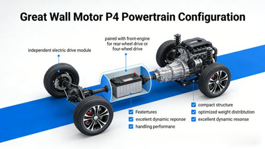
- Layout Logic: The electric motor sits on the rear axle, while the engine drives the front axle, making an AWD system without a mechanical driveshaft linking the two.
- Engineering Application: Brings pure electric RWD at low speeds and hybrid AWD at high speeds. It offers great passability but needs smart electronic synchronization of the front and rear power systems to stop power interference. (Examples: Li L8, Haval H6 DHT-PHEV)
6. Engineering Design Essentials for Powertrain Layouts
- Weight Distribution & Center of Gravity: The powertrain makes up 30%-50% of an EV’s weight (battery alone is 20%-35%). Engineers use simulation tools (ADAMS, ANSYS) to place components so the vehicle’s center of gravity stays low (500-600mm) and the load ratio stays near 1:1.
- Synergistic Thermal Management: Components have different operating temperatures (Motors: -40℃ to 150℃; Batteries: 0℃ to 55℃; ECUs: -40℃ to 125℃). Modern designs use integrated thermal modules, like the BYD e-platform 3.0’s “seven-in-one” multi-heat-source coupled thermal management system, to hit top cooling efficiency.
- Safety Protections: Batteries must sit outside structural crash buffer zones. Motors and ECUs need IP67 (passenger) or IP6K9K (commercial) ratings. Structural integration is a huge safety trend, like Tesla’s 4680 structural battery pack using integrated die-casting.
- Deep Integration: The main trend is “X-in-1” integration. BYD’s “8-in-1” electric drive packs 8 components together, dropping volume by 30% and weight by 20%. Nissan’s “14-in-1” system pushes power density to 4.5kW/kg. This stretches to Cell-to-Pack (CTP) and Cell-to-Chassis (CTC) tech, hitting the goal of “battery as structure, space as a service.”
7. Future Trends and Outlook
- “All-Domain” Integration: Moving past “X-in-1”, future platforms will merge power, thermal, and smart control systems completely. BYD’s advanced platforms using 1000V high-voltage architectures push system efficiency above 95%.
- Maturation of Distributed Architectures: “Corner module” tech (packing drive, steering, and suspension into a single wheel unit) will allow omnidirectional movement and true drive-by-wire control, fitting perfectly with autonomous driving.
- AI-Driven Smart Control: Powertrain layouts will sync deeply with ADAS. AI algorithms inside the ECU will dynamically adjust torque vectoring based on real-time road conditions, making “power follows demand” a reality.
- Lightweighting & Green Manufacturing: Heavy use of aluminum alloys and carbon fiber will balance out battery weight. The industry will lean heavily into full lifecycle green engineering and battery recycling.
8. The Bottom Line
The powertrain and transmission system layout acts as the foundation of a vehicle’s engineering profile. Centralized layouts (FWD, RWD, AWD) rule today’s market, while distributed layouts mark the highly efficient future. Hybrid setups (P2, P3, P4) bridge the gap well. By focusing on weight distribution, advanced thermal coupling, structural safety, and high-level component integration, automotive engineers can build safer, smarter, and greener vehicles.
9. Frequently Asked Questions (FAQ)
What is a powertrain layout in a vehicle?
Short Answer: It is the physical arrangement of the engine or motor and the transmission parts, deciding which wheels get power.
The powertrain generates power and sends it to the wheels. It includes the motor, transmission, driveshaft, differential, and axles. Common layouts include FF (Front engine, Front-wheel drive), FR, MR, RR, and AWD. These layouts directly change vehicle packaging, performance, and driving habits.
Why does powertrain layout matter in vehicle design?
Short Answer: It heavily changes a vehicle’s handling, weight balance, crash safety, and interior cabin room.
The location of the powertrain components decides the vehicle’s center of gravity and front-to-rear load ratio. A front-mounted single motor layout leaves maximum passenger space. A rear-mounted layout makes high-speed cornering balance much better. It is the core framework shaping driving dynamics.
What are the differences between FWD, RWD, and AWD drivetrain layouts?
Short Answer: FWD maximizes space and efficiency, RWD optimizes handling, and AWD maximizes traction and acceleration.
FWD uses less space and runs more efficiently due to fewer transmission parts, but handles worse at high speeds. RWD hits a near 50:50 weight distribution for great handling but needs tough thermal management packaging in the rear. AWD uses dual motors for heavy traction and 3-5 second 0-100km/h acceleration, but adds weight, cost, and control difficulty.
How are electric powertrain and transmission systems connected?
Short Answer: The transmission (usually a single-speed reducer in EVs) connects straight to the electric motor to match rotational speed and torque.
Unlike ICE vehicles that need multi-gear transmissions, electric powertrains mostly use a single-speed reducer built right in with the drive motor and MCU (making a 3-in-1 or higher integration assembly). This transmission adjusts the gear ratio so the motor’s high-speed rotation turns into the right torque needed to move the vehicle well.
