

< Back to Automotive Simulation Toolchain
Author: Johnny Liu
CEO — Dowway Vehicle
Last Updated: March 2026
- Quick Answer
- Why Finite Element Solvers Matter in Automotive Engineering
- What Is Simcenter Nastran?
- Core Solver Capabilities
- NVH Analysis Using Simcenter Nastran
- Large Model Simulation Capability
- Automotive Engineering Applications
- Suspension Durability Analysis
- Electric Vehicle Battery Pack Simulation
- CAE Toolchain Integration
- Industry Usage
- Future Directions in Vehicle Simulation
- Frequently Asked Questions
- What makes Simcenter Nastran different from other FEA solvers used in automotive CAE?
- How large models can Simcenter Nastran handle in full vehicle simulations?
- What automotive simulations are most commonly performed with Simcenter Nastran?
- How does Simcenter Nastran integrate with the automotive CAE toolchain?
- What are common challenges when using Simcenter Nastran?
- Author
Quick Answer
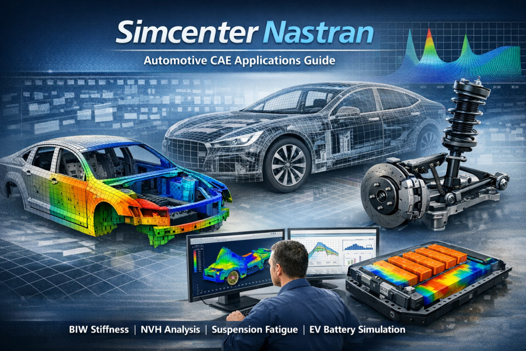
Simcenter Nastran is a finite element analysis solver used in automotive engineering to evaluate structural strength, stiffness, vibration behavior, fatigue life, and electric vehicle battery safety. The solver supports both linear and nonlinear analysis, handles very large models with millions of elements, and connects with CAE tools used for vehicle design and simulation.
Why Finite Element Solvers Matter in Automotive Engineering
Vehicle development relies heavily on computer simulation. Engineers use CAE tools to check structural safety, vibration performance, and durability before building physical prototypes.
Within a typical simulation workflow:
| Stage | Tool |
| Geometry design | CAD |
| Model preparation | HyperMesh / Simcenter 3D |
| Structural solving | Simcenter Nastran |
| Result visualization | HyperView / Simcenter Post |
| Engineering optimization | design tools |
The solver calculates structural equations produced by the finite element model.
Without the solver, simulation results cannot be generated.
What Is Simcenter Nastran?
Simcenter Nastran is a structural simulation solver developed from NASA’s original NASTRAN technology.
The software is now part of the Siemens Simcenter engineering platform and is widely used in:
- aerospace engineering
- automotive design
- heavy machinery
- energy systems
In automotive engineering the solver is commonly used to analyze:
- vehicle body structures
- chassis systems
- vibration and noise
- electric vehicle battery systems
The software is valued for numerical stability and reliable results when solving large structural models.
Core Solver Capabilities
Linear Structural Analysis
Linear analysis evaluates:
- stiffness
- stress
- deformation
Simcenter Nastran uses sparse matrix solution technology including the MUMPS solver.
Large vehicle structures can be solved efficiently while keeping prediction error within about 5% compared with physical tests.
Nonlinear Structural Analysis
Vehicle structures often experience nonlinear behavior.
Simcenter Nastran supports three main nonlinear categories.
Geometric Nonlinearity
Large deformation and displacement effects.
Material Nonlinearity
Plastic deformation and composite material damage.
Contact Nonlinearity
Surface-to-surface contact and point-to-surface contact between components.
These capabilities allow realistic simulation of structures such as suspension systems and battery packs.
NVH Analysis Using Simcenter Nastran
NVH means Noise, Vibration, and Harshness.
It is one of the main engineering tasks in vehicle design.
Simcenter Nastran includes several solver sequences for structural dynamics.
Modal Analysis — SOL 103
Modal analysis determines the natural frequencies and vibration modes of structures.
Engineers use these results to avoid resonance with:
- engine vibration
- electric motor frequencies
- drivetrain excitations.
Frequency Response Analysis — SOL 108
Frequency response analysis calculates vibration response under harmonic loads.
Applications include:
- vehicle body vibration
- powertrain excitation
- acoustic transfer paths.
Both direct frequency response and modal frequency response methods are supported.
Transient Dynamic Analysis — SOL 111
Transient analysis calculates time-dependent structural response.
Examples include:
- road impact loads
- vibration pulses
- transient structural forces.
When simulation models are calibrated with test data, modal predictions can match physical testing with over 90% correlation.
Large Model Simulation Capability
Modern full vehicle finite element models often contain millions or tens of millions of elements.
Simcenter Nastran handles these models through several computational methods.
Parallel Computing
Two computing modes are available.
SMP — Shared Memory Parallel
Multiple CPU cores share system memory.
DMP — Distributed Memory Parallel
Multiple computing nodes work together.
Parallel solving can increase performance by 30–50%.
Adaptive Mesh Refinement
The solver adjusts mesh density depending on stress distribution.
| Area | Mesh Density |
| Weld joints | fine mesh |
| Bolt locations | refined mesh |
| Low stress regions | coarse mesh |
This maintains accuracy while controlling computation time.
Model Reduction
Large models may be simplified before dynamic simulation.
Two common reduction methods are:
Component Mode Synthesis (CMS)
Preserves dynamic behavior of substructures.
Guyan Reduction
Removes less important degrees of freedom.
Reduced models are commonly used in multibody vehicle simulations.
Automotive Engineering Applications
BIW Structural Simulation
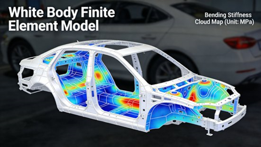
Body-in-white (BIW) is the main load-bearing structure of a vehicle.
Engineers analyze:
- bending stiffness
- torsional stiffness
- modal performance
- structural strength.
BIW Finite Element Modeling
BIW models include:
- sheet metal panels
- weld connections
- bolts.
To simplify models:
- holes smaller than 10 mm may be removed
- fillets smaller than 7 mm may be simplified.
This reduces computational cost.
Stiffness Test Simulation
Two common stiffness cases are simulated.
Bending stiffness
Vehicle body loaded vertically at the center.
Torsional stiffness
Opposite wheels constrained while torque is applied.
These load cases simulate uneven road conditions.
Example Engineering Result
In one compact vehicle development program:
- BIW bending stiffness increased 12%
- body weight decreased 8%
The improvement came from reinforcement changes and high-strength material replacement.
Suspension Durability Analysis
Suspension components experience repeated loads during driving.
Fatigue simulation predicts service life and identifies weak areas.
Suspension Model Components
Typical suspension models contain:
- control arms
- shock absorbers
- stabilizer bars
- bushings
- ball joints.
Bushings are modeled using nonlinear springs, while ball joints use hinge constraints.
Load Data
Loads may come from:
- road tests
- multibody simulations using ADAMS.
These loads are applied to the structural model.
Nonlinear Simulation
The nonlinear solver SOL 106 calculates stress and deformation under realistic loading conditions.
Stress concentrations often appear at weld joints.
Fatigue Life Prediction
Fatigue life is calculated using:
Miner linear cumulative damage rule
combined with the material S-N curve.
This predicts how many cycles a component can withstand.
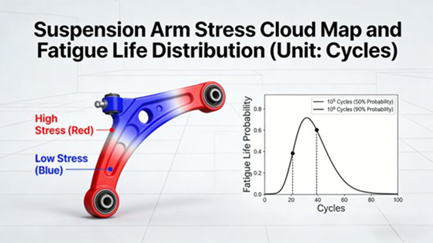
Example Result
For a suspension arm in an SUV design:
- initial life: 2 × 10⁵ cycles
After weld improvements:
- fatigue life increased to 1 × 10⁶ cycles.
Electric Vehicle Battery Pack Simulation
Electric vehicles introduce thermal and structural challenges.
Battery packs must remain safe during vibration and charging cycles.
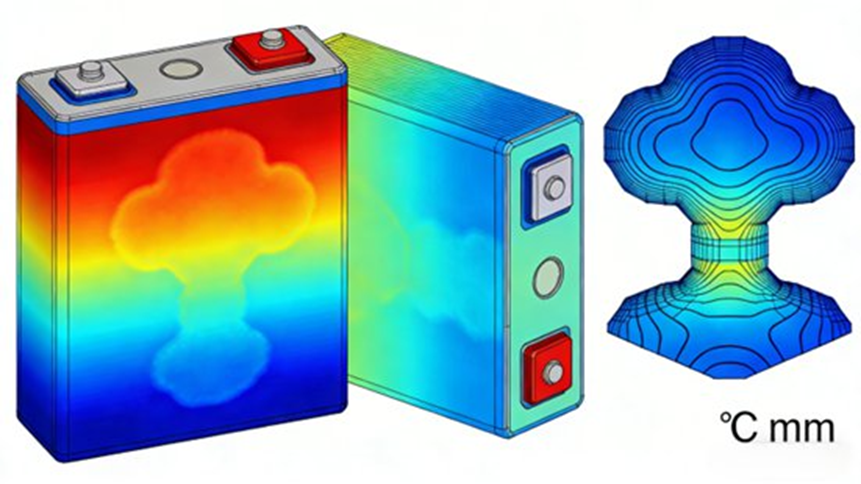
Battery Pack Finite Element Model
Typical model components include:
- battery modules
- pack housing
- cooling channels
- mounting brackets.
Battery modules use solid elements while housing structures often use shell elements.
Thermal-Structural Coupling
Two load categories are applied.
Thermal loads
Heat produced during charging and discharging.
Mechanical loads
Road vibration and impact forces.
Simcenter Nastran calculates both effects simultaneously.
Example Engineering Result
In one EV simulation project:
- maximum battery temperature reduced from 52°C to 38°C
- structural stress reduced 25%
This improvement came from cooling layout changes and housing reinforcement.
CAE Toolchain Integration
Simcenter Nastran works within a broader CAE environment.
Pre-Processing Tools
Model preparation tools include:
- HyperMesh
- Simcenter 3D
- CAD systems.
Supported file formats include:
- BDF
- INP
- STEP.
Post-Processing Tools
Simulation results can be visualized using:
- HyperView
- Simcenter 3D Post
- Tecplot.
These tools display stress maps, displacement fields, modal shapes, and fatigue results.
Multibody Dynamics Integration
Structural results can be used in vehicle dynamics models created in:
- ADAMS
- Simcenter Motion.
Control System Integration
For electric vehicle development, structural models may connect with control models built in:
- MATLAB
- Simulink.
Test Correlation
Simcenter Nastran connects with Simcenter Test Lab to compare simulation results with experimental measurements.
This improves model accuracy.
Industry Usage
Simcenter technology is used by many automotive companies.
Examples include:
Mazda Engineering & Technology
Simulation time for speaker grille analysis was reduced from 2.5 days to 4 hours.
American Axle & Manufacturing
Integrated NVH simulation with testing using Simcenter tools.
Hyundai Motor Group
Uses multi-physics simulation and digital twin platforms during electric vehicle development.
Future Directions in Vehicle Simulation
Several technology trends are influencing simulation tools.
Billion Element Vehicle Models
Future vehicle simulations may contain hundreds of millions or even billions of elements.
Multi-Physics Simulation
Vehicle models increasingly combine:
- structural mechanics
- thermal behavior
- fluid flow
- electromagnetics.
AI Assisted Simulation
Artificial intelligence may automate:
- model calibration
- simulation setup
- design optimization.
Digital Twin Engineering
Digital twins connect simulation models with real operating data during the vehicle lifecycle.
Frequently Asked Questions
What makes Simcenter Nastran different from other FEA solvers used in automotive CAE?
Simcenter Nastran is known for reliable structural and dynamics solver algorithms originally developed from NASA aerospace research.
It supports both linear and nonlinear finite element analysis including static, modal, frequency response, fatigue, and multi-physics simulations in one environment.
Engineers often mention:
- reliable results for large models
- strong NVH capabilities
- scalable parallel computing
- integration with the Simcenter CAE platform.
These features make it common in body structure analysis, chassis engineering, and powertrain NVH simulation.
How large models can Simcenter Nastran handle in full vehicle simulations?
Vehicle finite element models often exceed tens of millions of elements.
Simcenter Nastran handles these models through:
- SMP and DMP parallel computing
- efficient sparse matrix solvers
- model reduction techniques such as CMS.
Hardware configuration, solver settings, and model reduction strategy influence performance.
What automotive simulations are most commonly performed with Simcenter Nastran?
Engineers frequently use the solver for several vehicle development tasks.
BIW structural analysis:
- stiffness
- modal analysis
- structural strength
NVH analysis:
- modal frequencies
- vibration response
- transfer path analysis
Durability analysis:
- fatigue life prediction
- structural reliability
Chassis performance:
- suspension deformation
- load distribution
Electric vehicles:
- battery pack structural safety
- thermal-structural coupling.
How does Simcenter Nastran integrate with the automotive CAE toolchain?
Simcenter Nastran typically acts as the core solver within a multi-tool engineering environment.
Pre-processing tools include HyperMesh, Simcenter 3D, and CAD systems.
Post-processing tools include HyperView and Simcenter 3D Post.
System simulation tools may include ADAMS, Simcenter Motion, MATLAB, Simulink, and CFD software such as STAR-CCM+.
This environment supports complete digital engineering workflows.
What are common challenges when using Simcenter Nastran?
Engineers often report several practical issues.
Mesh quality problems:
- distorted elements
- inconsistent mesh density.
Material data problems:
- missing fatigue curves
- incomplete temperature properties.
Solver configuration issues:
- incorrect solver selection
- insufficient disk space
- result file errors such as *.f06 output problems.
Accurate boundary conditions and material data are essential for reliable simulation results.
Author
Johnny Liu
CEO — Dowway Vehicle
Johnny Liu works in vehicle engineering and CAE technology development. His work focuses on simulation-driven design, digital engineering workflows, and advanced vehicle development methods.
