

< Back to Platform Development
By Johnny Liu, CEO at Dowway Vehicle
Published: March 4, 2026 | Read Time: 15 minutes
- 1. Introduction: The Shift in Automotive Testing
- 2. Core Principles & Advantages of Controller HIL Testing
- 3. System Architecture: Building the Bench
- 4. Key Engineering Technologies
- 5. The V-Model Development Process
- 6. Real-World Engineering Applications
- 7. Next Steps in HIL Testing
- 8. Frequently Asked Questions (FAQ) About Car HIL Test Controllers
- 9. Final Thoughts
Key Takeaways:
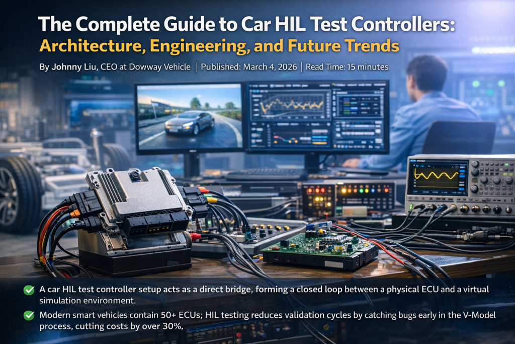
- A car HIL test controller setup acts as a direct bridge, forming a closed loop between a physical ECU and a virtual simulation environment.
- Modern smart vehicles contain 50+ ECUs; HIL testing reduces validation cycles by catching bugs early in the V-Model process, cutting costs by over 30%.
- Advanced HIL setups now integrate multi-GPU rendering, AI-generated edge cases, and microsecond-level latency to meet strict ISO 26262 (ASIL D) and ASPICE standards.
1. Introduction: The Shift in Automotive Testing
Cars today act like smart terminals. They mix mechanics, electronics, and software into a single system. Traditional cars had maybe 10 to 20 Electronic Control Units (ECUs). Now, smart driving models pack over 50 ECUs. They manage everything from the powertrain to chassis safety and advanced driver-assistance systems (ADAS).
This jump in complexity makes testing hard. Track testing costs too much money, takes too long, and limits what you can do safely. You cannot easily recreate a battery thermal runaway or a sudden sensor drop in real life without risking human safety. Finding a design flaw late in the prototype stage also means massive repair costs.
Hardware-in-the-Loop (HIL) testing fixes this problem. You plug the real car HIL test controller (the ECU) into a virtual setup. This moves validation to the early design stages. It keeps things safe, speeds up work, and helps teams hit ISO 26262 and ASPICE standards right from the start.
2. Core Principles & Advantages of Controller HIL Testing
The Closed-Loop Logic
HIL testing relies on a “Closed-Loop Simulation.” A fast computer builds a virtual car, the environment, and the physical load. You plug the physical ECU into this digital world. The loop goes: ECU -> Virtual Environment -> ECU.
The simulator runs dynamics and sensor models, sending signals (like speed or braking) to the ECU. The car HIL test controller reads these signals, makes decisions based on its algorithms, and fires back commands. The simulator updates the scene instantly. Think of it like a highly realistic racing video game, but the ECU sits in the driver’s seat.
HIL Testing vs. Traditional Physical Testing
| Feature | Traditional Physical Testing | Car HIL Test Controller System |
| Safety | High risk (testing thermal runaway or braking failures). | 100% Safe (simulated extreme scenarios). |
| Speed | Slow, reliant on weather, location, and physical builds. | 24/7 Automated, finishing months of work in days. |
| Cost | Very high (prototypes, tracks, fuel, human labor). | Drops overall testing costs by >30%. |
| Fidelity | Real world, but hard to catch hardware bugs early. | High, captures PCB noise, interface levels, and timing misses. |
| Rules | Hard to document edge cases repeatedly. | Directly supports ISO 26262 & ASPICE certification. |
3. System Architecture: Building the Bench
A complete car HIL test controller system needs custom parts depending on the ECU. The core setup uses five main blocks working together.
3.1 The Test ECU Module
Different ECUs require specific wiring harnesses, mounting brackets, and heat sinks.
- Powertrain: Engine Control Unit (ECU), Transmission Control Unit (TCU), Motor Control Unit (MCU), Battery Management System (BMS).
- Chassis: Anti-lock Braking System (ABS), Electronic Stability Program (ESP), Electric Power Steering (EPS).
- Smart Driving: ADAS controllers, Autonomous Driving Domain Controllers (ADC), LiDAR/Camera nodes.
- Body: Body Control Module (BCM), Air Conditioning Unit (ACU), Gateway (GW).
3.2 Real-Time Simulation Module
The brain needs extreme speed. We aim for a simulation step of ≤1ms.
- Processors: Teams use multi-core CPU + FPGA setups (like dSPACE SCALEXIO or NI PXI). FPGAs handle fast signals; CPUs do the heavy math.
- Software: Tools like Matlab/Simulink, dSPACE ConfigurationDesk, and NI VeriStand support ASAM OpenDRIVE/OpenSCENARIO and link with ROS2/TROS.
- Virtual Models: High-fidelity vehicle dynamics and sensor models (handling lens distortion, dynamic blur, point cloud reflectivity) calibrate down to a simulation error of ≤5%.
3.3 I/O Interface Module
This bridge translates virtual signals to hardware signals with latency at ≤10μs.
- Analog I/O: Simulates sensors with precision at ≤0.1% FSR.
- Digital I/O: High/low voltage switches.
- Buses: CAN, CAN FD, LIN, Ethernet (1000/100BASE-T1), and FlexRay. High-end systems use GMSL/LVDS interfaces to send raw ADAS sensor data directly.
3.4 Test Management Module
Software like dSPACE ControlDesk, Vector CANoe, or NI VeriStand runs Python and LabVIEW scripts. It grabs high-frequency data (100Hz–10kHz, storing in CSV/MAT formats) and builds automated reports.
3.5 Load and Fault Injection Module
- Load Simulators: Use RLC components to mimic real electrical loads, like an injector’s PWM drive capacity.
- Fault Injection Unit (FIU): Simulates open/short circuits and signal drifts in milliseconds to check ECU diagnostic logic.
4. Key Engineering Technologies
4.1 Speed Optimization
Engine ECUs run fine on a step of ≤1ms. ADAS domain controllers need microsecond-level steps. Multi-GPU setups jump in here to run complex scenes, boosting testing speed by over 50%.
4.2 Model Calibration
Engineers grab real road data to set the models. For ADAS, tweaking sensor models helps push multi-target detection Recall up to 64.68%.
4.3 Automation Scripts
Using Python or LabVIEW, teams run equivalence class partitioning and boundary value analysis. For ADAS, tools like AutoGI (scenario generation) and Log2World (scenario reconstruction) push the limits on edge cases. Automation makes HIL testing 3 to 5 times faster.
4.4 Fault Injection & Safety
To hit ASIL A-D ratings, setups use Latin Hypercube sampling and Bayesian adaptive algorithms. We prove the test works using metrics like the Kolmogorov-Smirnov test and KL divergence. For example, engineers might simulate an ESP wheel speed sensor open circuit or an ADAS LiDAR failure to test the backup logic.
5. The V-Model Development Process
HIL testing runs right alongside ECU development via the V-Model:
- Requirements: Define targets, scope, and pick platforms (dSPACE for powertrain, NI PXI for ADAS, ETAS for AUTOSAR projects, or custom builds for tight budgets).
- Setup & Debugging: Configure the hardware, map the buses, and calibrate the models.
- Case Design: Write the automated test scripts.
- Execution: Run batch tests and grab high-frequency logs.
- Analysis: Compare actual outputs to what you expected to find bugs.
- Reporting: Print ISO 26262/ASPICE documents to get approval for production.
6. Real-World Engineering Applications
Case 1: New Energy Vehicle BMS Controller
- Requirements: ASIL C safety. Must handle charge/discharge, thermal management (-30°C to 60°C), and diagnostics.
- Setup: dSPACE SCALEXIO (0.5ms step), 32 analog/8 digital I/O, CAN/CAN FD buses, and cell load simulators.
- Results: We ran 120 automated cases (100% automation, 95% coverage). We tested 0.5C, 1C, and 2C rates, keeping voltage precision error ≤2%. Thermal controls held the battery at 20°C–40°C (error ≤1°C). We threw 15 faults at it (short circuits, bad temp sensors) and got 100% diagnostic accuracy (≤100ms response). We caught 3 logic flaws, cut R&D time from 6 to 3.5 months, and dropped real-car tests by 80%.
Case 2: L3 Autonomous Driving Domain Controller (ADC)
- Requirements: ASIL D safety for NVIDIA Hyperion 8.1 architecture. Must simulate 12 Cameras + 9 Radars + 1 LiDAR.
- Setup: NI PXI distributed platform with multi-GPUs. It runs NeRF/3DGS and ray-tracing rendering at 0.1ms steps. Uses 10Gbps Ethernet, CAN FD, and GMSL/LVDS transmission (latency ≤1ms).
- Results: We ran 200 test cases using NI VeriStand and Python (90% automation, 98% coverage). Perception accuracy hit ≥99% (≤50ms response). The sensor fallback worked perfectly. We caught 5 decision-planning defects, clearing the path for ASIL D compliance.
7. Next Steps in HIL Testing
- Ultra-High Graphics: Sensor models now handle hard physics like radar multipath effects and rain attenuation. Current setups hit a smooth 14 FPS in full ray-tracing modes.
- AI & Digital Twins: AI writes Corner Cases on its own. Teams move test scripts smoothly across SiL, MiL, and HIL. Digital twins sync data between the lab bench and cars on the real road.
- Multi-ECU & V2X: Teams test whole groups at once (MCU + BMS + VCU). They tie in Vehicle-to-Everything (V2X) tech to simulate crowded city traffic.
- Cloud-Edge Setups: Heavy math runs online while real-time I/O clicks at the edge. This drops hardware costs dramatically.
- Cybersecurity Rules: Teams merge ISO 26262 with ISO/SAE 21434. HIL controllers face fake CAN bus hacks and LiDAR spoofing to lock down car security.
8. Frequently Asked Questions (FAQ) About Car HIL Test Controllers
What is a Car HIL Test Controller?
Short Answer: It is a hardware and software setup that tests real car ECUs inside a safe, simulated digital world.
In practice, the physical controller hardware connects to a real-time simulator modeling the engine, battery, sensors, and environment. The controller performs tasks like:
- Running automated test cases
- Managing complex simulation models
- Injecting faults and edge-case conditions
- Monitoring high-frequency signals and data
- Logging results and generating compliance reports
How Does Automotive HIL Testing Work?
Short Answer: It builds a fast closed control loop between a physical car computer and a virtual environment.
The core process involves:
- The Real ECU: The physical hardware under test.
- The Real-Time Simulator: A fast processor running math models of the car parts.
- The I/O Interface: The hardware bridge exchanging signals between the ECU and simulator.
- The Test Software: The platform running the automated scenarios.
The simulator sends virtual sensor data to the ECU. The ECU processes it and sends commands back. The simulator reacts instantly, acting exactly like a real car on a real road.
Why Is HIL Testing Important in Automotive R&D?
Short Answer: It lets engineers catch software bugs early and test dangerous scenarios safely, saving money and time.
Because cars run on complex software, HIL testing helps teams:
- Detect integration bugs early in the design phase.
- Test bad scenarios safely, like battery thermal runaway or severe sensor failures.
- Validate system behavior before paying for full physical prototypes.
- Shrink development costs and get cars to market faster.
What Automotive Systems Are Typically Tested with HIL?
Short Answer: Engineers test almost every smart system in a car, from the powertrain to self-driving brains.
Common applications include:
- Powertrain: Engine Control Units (ECU) and Transmission Control Units (TCU).
- New Energy: Battery Management Systems (BMS) and Motor Control Units (MCU).
- Smart Driving: Advanced Driver Assistance Systems (ADAS) and Autonomous Driving Domain Controllers.
- Chassis & Safety: Electronic Stability Programs (ESP) and Anti-lock Braking Systems (ABS).
What Are the Key Components of an Automotive HIL Test System?
Short Answer: A solid setup needs a fast computer, the car part itself, signal bridges, software, and fault simulators.
A professional HIL bench integrates:
- Real-Time Simulator: The computer running the math models.
- Controller Under Test (ECU): The physical hardware.
- I/O Interfaces: Signal converters (analog, digital, CAN, LIN, Ethernet).
- Test Software: The command center controlling scenarios and grabbing data.
- Load and Fault Injectors: Physical hardware used to fake electrical loads and trigger system breaks.
9. Final Thoughts
The car HIL test controller sits at the heart of modern automotive engineering. By building a tight loop between real hardware and virtual physics, it removes the biggest roadblocks of physical testing. It cuts costs, shrinks timelines, and proves the safety limits of the car.
As computing gets faster, bringing AI, cloud setups, and ultra-high graphics into the lab will push testing speeds even higher. For engineering teams, mastering these setups is the clearest path to building safer, smarter cars.
