

< Back to Vehicle Design & Engineering Hub
Author: Johnny Liu, CEO at Dowway Vehicle
Published Date: February 26, 2026
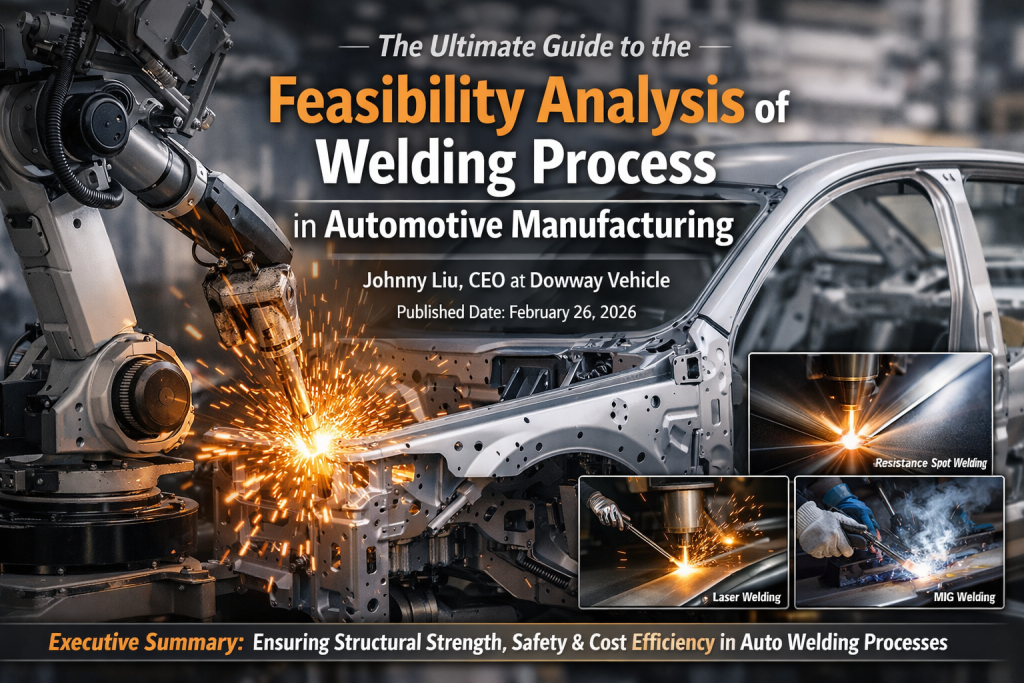
Executive Summary: Welding acts as the core joining technology in auto manufacturing. It directly determines body structural strength, collision safety, assembly precision, and the overall service life of the vehicle. Running a rigorous feasibility analysis of your welding process is the critical first step before starting R&D and mass production. This guide breaks down mainstream welding processes. It builds a step-by-step feasibility analysis framework based on six core dimensions. This gives you the technical support needed to mitigate risks and balance quality, efficiency, and costs on the factory floor.
- 1. Introduction: The Need for Feasibility Analysis
- 2. Mainstream Automotive Welding Processes & Application Scenarios
- 3. Core Dimensions of Welding Process Feasibility Analysis
- 3.1 Material Adaptability (The Core Prerequisite)
- 3.2 Process Parameter Rationality (The Core Focus)
- 3.3 Equipment Compatibility (Mass Production Guarantee)
- 3.4 Quality Controllability (The Ultimate Goal)
- 3.5 Cost Economics (The Key to Implementation)
- 3.6 Environmental Compliance (The Mandatory Requirement)
- 4. Standardized Workflow for Feasibility Analysis
- 5. Real-World Case Study: White Body D-Pillar
- 6. Risk Identification and Mitigation Strategies
- 7. Frequently Asked Questions (FAQ) on Welding Feasibility
- 8. Final Thoughts & Future Outlook
💡 Key Takeaways (TL;DR)
- Core Challenge: The shift toward EV and lightweight vehicles requires joining complex multi-material mixes (high-strength steel, aluminum, magnesium).
- Process Selection: Different applications require specific methods. You might use Resistance Spot Welding (RSW) for body frames, Laser Welding (LW) for high-precision roof joints, or Arplas Welding for clean D-pillars.
- The 6-Dimension Framework: A successful feasibility study must evaluate: 1. Material Adaptability, 2. Process Parameters, 3. Equipment Compatibility, 4. Quality Controllability, 5. Cost Economics, and 6. Environmental Compliance.
- Standardized Workflow: Feasibility moves from initial selection and multi-dimensional assessment to trial verification (DoE) and final SOP implementation.
1. Introduction: The Need for Feasibility Analysis
The automotive industry is shifting fast toward EVs, lightweighting, and smart tech. Because of this, car bodies now use complex multi-material mixes. This shift puts strict demands on the precision, strength, and efficiency of your joining technologies.
Analyzing the feasibility of automotive welding processes is not a simple check-the-box exercise. You have to look at the whole picture—spanning product design, process planning, equipment selection, and mass production verification. The core objective is to answer three basic questions:
- Can the selected process meet the design requirements?
- Can it adapt to the demands of mass production?
- Can it achieve an optimal balance between quality and cost?
2. Mainstream Automotive Welding Processes & Application Scenarios
Different welding processes have distinct principles, advantages, application scenarios, and technical thresholds. Your feasibility analysis begins with a preliminary selection based on part function, material type, and production volume.
2.1 Resistance Spot Welding (RSW)
RSW remains the most widely used process in auto body welding. It handles over 80% of the total welding volume on a car body. The system uses electrode pressure and Joule heating from contact resistance to melt the overlapping metal sheets locally.
- Advantages: Extremely fast (single spot welding time ≤0.5s), low cost, and easy to automate for mass production.
- Limitations: Only works for thin sheet lap joints. It leaves indentations and cannot handle thick plates or complex curved seams.
- Applications: Body-in-white (BIW) frames (A/B/C pillars, sills, longitudinal/cross beams), door panels, hoods, and trunk lids. A standard sedan typically requires 3,000 to 6,000 spot welds.
[Image Placeholder: Resistance Spot Welding (RSW) for Automobile Body Frame]
2.2 MIG/MAG Welding (Metal Inert/Active Gas)
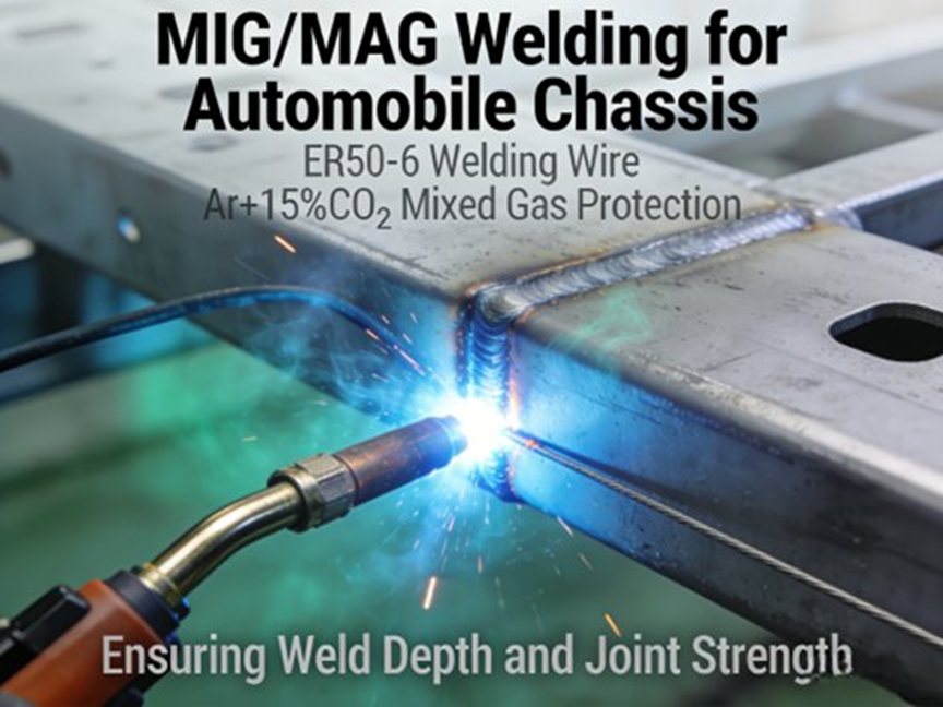
As a type of arc welding, MIG/MAG uses a continuous wire electrode and shielding gas (Inert gas like Ar for MIG; Active mixed gas like Ar+CO₂ for MAG) to protect the weld pool.
- Advantages: Deep penetration and high adaptability. It works for low-carbon steel, high-strength steel, and aluminum alloys (both thin and thick plates).
- Limitations: Slower than RSW, needs a strict environment (no wind/dust), and often produces spatter that requires post-weld cleaning.
- Applications: Thick-walled structures like chassis longitudinal beams, crossbeams, control arms, and aluminum body parts. MAG is widely used for high-strength steel chassis parts due to lower costs. Engineers prefer MIG for aluminum.
[Image Placeholder: MIG/MAG Welding for Automobile Chassis]
2.3 Laser Welding (LW)
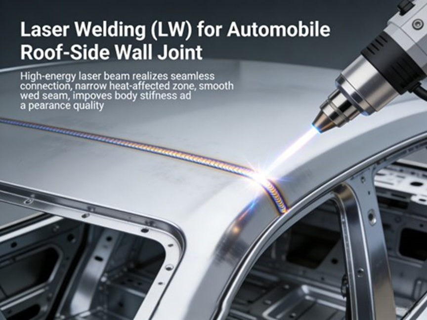
A standard in high-end auto manufacturing, LW uses a high-energy-density laser beam to instantly melt the base material.
- Advantages: Extremely small heat-affected zone (≤1mm), minimal distortion, smooth seams, and high speed (500-1000mm/min). Excellent for unequal thickness sheets and complex curves.
- Limitations: High equipment cost (5-10 times that of normal welders), extremely strict assembly gap requirements (usually ≤0.1mm), and high operator skill requirements.
- Applications: High-end roof and side-wall joints (replacing spot welding for a seamless look), tailored blanks for door panels, engine blocks, transmission cases, and EV battery trays.
[Image Placeholder: Laser Welding (LW) for Automobile Roof-Side Wall Joint]
2.4 Stud Welding (SW)
SW instantly melts the contact surface of a stud and a metal plate using a high current, pressing them together.
- Advantages: Fast, reliable, leaves no marks on the reverse side, and eliminates the need for drilling or tapping.
- Limitations: Only works for stud-to-plate connections.
- Applications: Welding studs for interior trim panels, wiring harnesses, sound insulation cotton, carpets, and chassis/engine brackets.
2.5 Brazing
Brazing uses a filler metal (e.g., copper or zinc-based) with a lower melting point than the base metal. Capillary action draws the melted filler into the joint without melting the base metal itself.
- Advantages: Smooth and highly aesthetic joints, excellent sealing, minimal thermal distortion, and suitable for dissimilar metals.
- Limitations: Lower joint strength than fusion welding; unsuitable for high-load components.
- Applications: Roof drip moldings, door hems, exhaust pipes, and steel-to-copper connections.
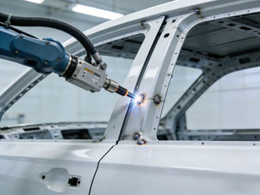
2.6 Arplas Welding
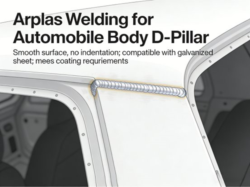
Arplas is a highly efficient process combining the benefits of arc and laser welding by optimizing arc shape and energy distribution.
- Advantages: Joint strength matches RSW, but the aesthetics are vastly superior. It leaves virtually no indentation (invisible after painting) and features ductile fracture characteristics. This makes it ideal for galvanized sheets.
- Limitations: Strict requirements on workpiece radius of curvature and overlap width; unsuitable for three-layer plate structures.
- Applications: High-perception areas like BIW D-pillars, doors, and combinations of galvanized and standard steel sheets.
[Image Placeholder: Arplas Welding for Automobile Body D-Pillar]
3. Core Dimensions of Welding Process Feasibility Analysis
3.1 Material Adaptability (The Core Prerequisite)
Mismatching process to material leads to severe defects like incomplete penetration, cracks, or porosity.
- Base Material Types: Aluminum has high thermal conductivity and oxidizes quickly. This makes it a poor fit for RSW (leads to undersized nuggets) but ideal for MIG/Laser. High-strength steel has high carbon content and is prone to cold cracking. It requires precise heat input control (e.g., Laser or optimized MAG) and preheating/insulation.
- Dissimilar Materials: Joining steel to aluminum requires Brazing or Laser hybrid welding with specific fillers to minimize brittle intermetallic compounds.
- Surface Conditions: Galvanized zinc layers vaporize and cause porosity. They require processes that quickly melt zinc (like Arplas) or pre-removal. High-strength steel scales require shot blasting (Roughness Ra 1.6-3.2μm) and phosphating (film weight 2-5g/m²).
3.2 Process Parameter Rationality (The Core Focus)
Poor parameter settings lead to defects and efficiency drops.
- RSW: Key parameters for 2-5mm thin plates include 800-1500A current, 0.3-0.8MPa pressure, 0.2-0.5s time, and a nugget diameter ≥3 times the plate thickness.
- MIG/MAG: Current density >300A/mm² causes undercut. Gas flow must remain stable (fluctuation ≤5%). For MAG, an Ar+CO₂ ratio of 80:20 works best; CO₂ >25% significantly increases spatter. Wire extension should strictly stay between 10-15mm (fluctuation ≤1mm).
- Laser: Defocusing amount is typically set at +2 to +5mm to ensure uniform spot energy.
- Arplas: Overlap width should be 4-7mm, and the workpiece radius of curvature must be >150mm to prevent false welding. Three-layer structures should move to a two-layer design.
- Optimization Tip: Using “inside-out, short-then-long, symmetrical welding” sequences can limit total distortion to ≤3mm.
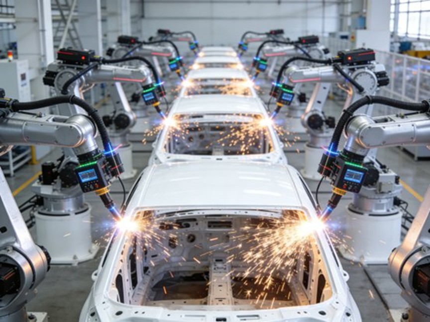
3.3 Equipment Compatibility (Mass Production Guarantee)
- Performance Matching: Laser equipment needs power stability (fluctuation ≤±1%) and high repeat positioning accuracy (≤±0.05mm). RSW needs fast response (mainline cycle time ≤60s/car). Robots require laser tracking systems (scanning frequency ≥100Hz, accuracy ±0.1mm).
- Line Integration: Equipment must match existing conveying/positioning tooling. New laser systems require specific cooling water environments (inlet temp difference ≤5℃).
- Maintenance: RSW contact tips typically need replacement every 500-800 spots.
[Image Placeholder: Automated Welding Robot Production Line]
3.4 Quality Controllability (The Ultimate Goal)
Welding quality must meet strict standards like ISO 13919-1 and GB/T 26743.
- Defect Prevention: Control gas flow, surface cleanliness (oil residue ≤5mg/m²), and shielding gas dew point (≤-40℃) to stop porosity. Keep a 70°-80° torch angle to avoid undercut.
- Inspection & Repair: RSW uses Ultrasonic Testing (UT); Laser uses Radiographic Testing (RT) or high-res vision (≥12MP). Critical torque-bearing parts require 100% Magnetic Particle Testing (MT), failing if linear defects ≥0.5mm exist.
- Consistency (SPC): By using closed-loop control on chassis crossbeams, one automaker reduced porosity rates from 5.2% to 0.3% and increased RT Level I pass rates to 99.5%.
3.5 Cost Economics (The Key to Implementation)
Cost evaluation covers equipment, consumables, labor, energy, maintenance, and rework.
- Real-world impact: Tweaking MIG parameters for EV battery trays reduced spatter by 65% and cut cleaning time from 12s to 4s per piece. For HC340LA chassis crossbeams, Laser welding increased efficiency by 40% and reduced costs by 38% compared to MIG.
3.6 Environmental Compliance (The Mandatory Requirement)
- Emissions & Waste: Exhaust must meet GB 2890-2019 and GB 16297-1996. Wastewater must meet GB 8978-1996.
- Noise: Equipment noise must remain ≤85dB to comply with GBZ 2.2-2007.
4. Standardized Workflow for Feasibility Analysis
- Preliminary Preparation: Define mechanical and aesthetic requirements, material specs, scale, and cycle time.
- Initial Selection: Filter 2-3 potential processes based on material and goals (e.g., skip RSW for aluminum).
- Multi-dimensional Assessment: Evaluate using the 6 core dimensions mentioned above.
- Trial Verification: Run small-sample and pilot production to test parameters, quality, and costs.
- Review & Optimization: Select the best plan and propose continuous tweaks.
- Final Implementation: Install equipment, establish Standard Operating Procedures (SOPs), train personnel, and monitor batch production.
5. Real-World Case Study: White Body D-Pillar
- Background: D-pillar using galvanized sheet/DC01 steel, 2.0mm thick. Production: 2000 units/day. Requirements: Tensile strength ≥3000N, deformation ≤0.2mm/m, defect rate ≤0.5%, with invisible joints after painting.
- Initial Selection: RSW and Arplas (Laser excluded for high cost, MIG for poor aesthetics).
- Evaluation & Trials (1000 pieces each):
- RSW: Parameters (1200A, 0.3s, 0.5MPa, 10mm electrode). Results: 3200N strength, 1.3% defect rate (porosity/indentations), 0.18mm/m deformation. Consumable cost: 0.8 RMB/pc. Failed aesthetic requirements due to visible indentations.
- Arplas: Parameters (180A, 22V, 200mm/min speed, 5mm overlap). Results: 3351N strength, 0.2% defect rate, 0.15mm/m deformation. New equipment cost: 500,000 RMB. Consumable cost: 0.9 RMB/pc. Met all requirements perfectly.
- Outcome & Implementation: The team selected Arplas. By tweaking welding speed to 220mm/min and adding an auto-grinding tool for minor spatter, the mass production defect rate stabilized below 0.1%. The new equipment achieved ROI in just 6 months due to heavy paint rework savings.
6. Risk Identification and Mitigation Strategies
6.1 Core Risks
- Technical: Bad material assessment or poor parameter setups leading to defects.
- Cost: Budget overruns on equipment or high consumable/rework costs extending ROI.
- Environmental: Failing local emissions tests, causing production halts.
- Personnel: Operator errors or poor maintenance habits due to a lack of training.
6.2 Countermeasures
- Run rigorous pilot testing and 3D simulation.
- Build accurate cost-models and form strategic supplier partnerships.
- Track local environmental regulations closely and adopt green consumables.
- Enforce mandatory, system-wide SOP training for all operators and technicians.
7. Frequently Asked Questions (FAQ) on Welding Feasibility
Q1: What factors should I consider when doing a feasibility analysis for a welding process?
A: A thorough feasibility study must evaluate several core elements to ensure manufacturing works:
- Material type and weldability: Different metals react differently to heat and dictate the required process.
- Joint design and position: The accessibility and geometry decide which welding gun or robot you can use.
- Process parameters: Testing voltage, current, speed, and filler choice to balance quality and stop distortion.
- Cost & ROI: Factoring in equipment investment, labor, consumables, and expected throughput.
- Skill and equipment availability: Checking whether your facility has the trained personnel to run the chosen process.
Q2: How do I determine whether a welding process is economically feasible?
A: Economic feasibility goes beyond the initial price tag of the equipment. Run a detailed cost estimation that includes labor, machine operation, consumables, and projected rework reductions. Evaluate your expected production volume—high-volume jobs often justify the upfront cost of automation, whereas low-volume runs might not. Always factor in long-term maintenance and training costs to calculate a realistic Return on Investment (ROI).
Q3: What makes a welding method technically feasible or not?
A: Technical feasibility depends on whether the process can consistently produce a joint that meets design and safety standards. Engineers check material compatibility, joint fit-up tolerances, and the likelihood of defects. Industry best practices highly recommend running controlled empirical tests—such as Design of Experiments (DoE) or small experimental runs—to validate weld quality before you commit to full-scale production.
Q4: How do I perform a feasibility study for robotic welding integration?
A: Assessing robotic welding requires looking beyond the weld itself. You must evaluate the entire manufacturing cell. Analyze part geometry, dimensional tolerances, and the robot’s reach. Check your pre-welding operations and fixture design, as consistent part fit-up is mandatory for automation. Finally, weigh the initial investment against the expected boost in throughput, quality consistency, and workflow changes on the floor.
Q5: What criteria do engineers use to pick the “best” welding process?
A: There is no universal “best” process; you simply need the optimal match for specific constraints. Engineers base decisions on:
- Material thickness and properties: Dictating deep-penetrating vs. low-heat-input methods.
- Weld quality and aesthetics: Seamless joints (Arplas/Laser) vs. structural-only joints.
- Production speed: Balancing rapid cycle times against required precision.
- Environmental conditions: Factoring in shop floor conditions (e.g., drafts blowing away gas shielding).
- Cost constraints: Aligning with the project’s budget for initial setup and labor.
8. Final Thoughts & Future Outlook
Feasibility analysis acts as a critical gatekeeper in auto manufacturing. By relying on the 6-dimension framework—Materials, Parameters, Equipment, Quality, Costs, and Environment—engineers reliably mitigate mass-production risks and ensure vehicles are built safely and efficiently.
Future Trends:
- Intelligent Analysis: Using AI and Big Data to predict defects and fine-tune parameters automatically.
- Multi-process Fusion: Combining processes (e.g., Laser + Brazing or Stud + Adhesive) to handle complex multi-material joints.
- Full Lifecycle Analysis: Pushing evaluations from design and mass production all the way to vehicle maintenance, scrapping, and recycling to match green manufacturing goals.

·