

< Back to Platform Development
By Johnny Liu, CEO at Dowway Vehicle | Published: March 5, 2026
The new energy vehicle (NEV) industry is growing fast. Automotive motors operate as the core power and auxiliary execution units. The performance of their control systems directly dictates the vehicle’s dynamics, economy, and safety. Simulation technology replaces the traditional “physical trial-and-error” R&D model. It lowers costs, increases efficiency, and makes testing repeatable.
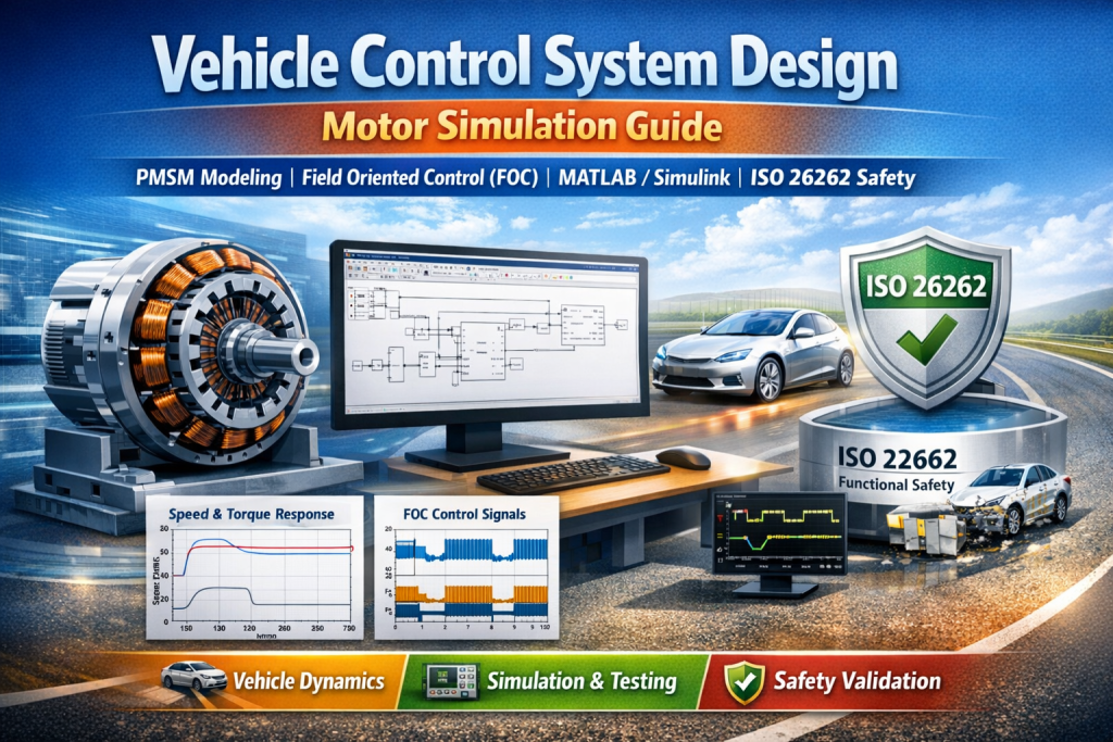
This guide details the simulation design process of automotive motor control systems—a core part of vehicle control system design. We focus on Permanent Magnet Synchronous Motors (PMSM), system modeling, control strategy design, and real-world engineering validation.
- 1. The Shift to Simulation in Modern Systems
- 2. Fundamentals of Simulation for Vehicle Motor Control
- 3. System Modeling for Automotive Motor Controllers
- 4. Core Control Strategies in Vehicle System Design
- 5. Simulation Validation and Performance Analysis
- 6. Frequently Asked Questions in Vehicle Control System Design
- Bonus: The MPC Vehicle Control Design Workflow
1. The Shift to Simulation in Modern Systems
Motors drive systems, steering, and braking in pure electric and hybrid vehicles. The control system is the “brain.” It receives commands from the Vehicle Control Unit (VCU) and executes algorithms to regulate speed, torque, and current.
The traditional R&D cycle of “hardware construction -> physical testing -> parameter adjustment” takes too long and costs too much. Extreme conditions, like rapid acceleration or low-temperature starts, often break physical hardware. By building a virtual environment for the motor, controller, and vehicle, engineers spot design flaws early and fix parameters safely. This “virtual validation to physical iteration” method is standard practice today.
2. Fundamentals of Simulation for Vehicle Motor Control
Core Objectives of Simulation Design
In engineering practice, simulation targets precise modeling, quick validation, and better performance. Specifically, we aim to:
- Replicate dynamic responses with an error margin of ≤5% compared to physical tests.
- Validate control strategies across all conditions. Keep speed error ≤±1% and torque ripple ≤±2%.
- Tune parameters to lower copper and iron losses, boosting system efficiency.
- Simulate fault scenarios (like broken sensors) to check fault tolerance and meet ISO 26262 standards.
The 7-Step Simulation Workflow
We use MATLAB/Simulink (along with Motor Control Blockset and Simscape Electrical) because it supports multi-domain co-simulation (e.g., with Carsim) and automatic embedded C code generation. The workflow involves:
- Requirement Analysis: Define motor specs and vehicle conditions.
- System Modeling: Build the plant, sensor, controller, and inverter models.
- Control Strategy Design: Apply algorithms like Field Oriented Control (FOC).
- Simulation Setup: Integrate modules and configure variable steps.
- Simulation Validation: Test startup, acceleration, and braking.
- Parameter Optimization: Tune PID and SVPWM variables.
- Hardware Verification: Port code to the Microcontroller Unit (MCU).
3. System Modeling for Automotive Motor Controllers
PMSM Body Modeling
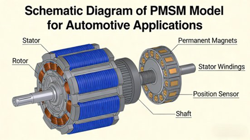
The PMSM model uses the $dq$ rotating coordinate system to describe electromagnetic characteristics. The core mathematical equations are:
Voltage Equations:
u_d=R_si_d+L_d\frac{di_d}{dt}-\omega_eL_qi_q
u_q=R_si_q+L_q\frac{di_q}{dt}+\omega_eL_di_d+\omega_e\psi_f
Torque Equation:
T_e=1.5p(\psi_fi_q+(L_d-L_q)i_di_q)
Mechanical Equation:
T_e-T_L=J\frac{d\omega_m}{dt}+B\omega_m
For our simulation, we input typical vehicle parameters: 50kW rated power, 15000rpm, 4 pole pairs, 0.02Ω stator resistance, 0.5mH dq-axis inductance, 0.175Wb flux linkage, and 0.01kg·m² moment of inertia.
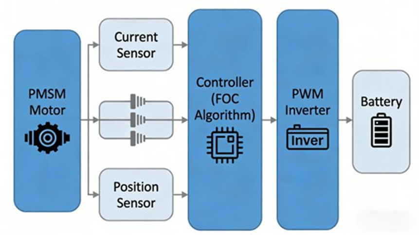
Power Converter & Sensor Modeling
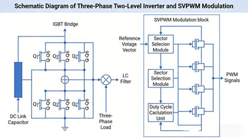
- Inverter: A three-phase two-level topology (6 IGBTs, 6 diodes). We set the IGBT switching frequency to 10kHz, a dead-zone of 3μs, fed by a 400V battery (standard range is 300-800V).
- Current Sensors: Hall-effect sensors measuring -200A to 200A with ±0.5% accuracy and 0.1% simulated noise.
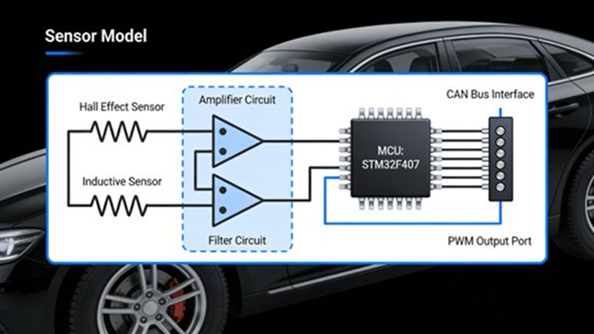
- Position Sensor: A 16-bit Resolver model handles high-precision rotor tracking.
The controller model processes ADC conversion, Clarke (3-phase to αβ) and Park (αβ to dq) transforms, dual closed-loop loops, and final PWM generation.
4. Core Control Strategies in Vehicle System Design
Field Oriented Control (FOC)
FOC transforms stator currents into excitation current (i_d) and torque current ($i_q$). For surface-mounted vehicle PMSMs, we use the i_d=0 strategy. Torque is governed only by i_q, keeping the motor running efficiently.
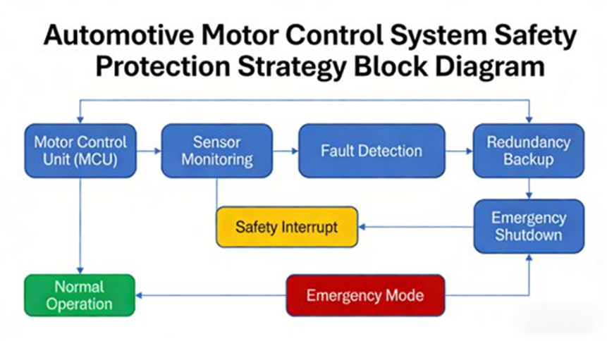
Parameter Optimization & ISO 26262 Safety
The current loop must respond 10x faster than the speed loop. We target a startup time of ≤0.5s, overshoot ≤5%, speed error ≤±1%, and torque ripple ≤±2%. We also add feedforward control to handle sudden load changes, like hill climbing.
To stay safe and meet ISO 26262 rules, the model cuts PWM if current goes over 1.5x rated limits or battery voltage goes over 1.1x. It drops power output if temperatures exceed 150°C and switches to open-loop modes if sensors fail.
5. Simulation Validation and Performance Analysis
We ran a simulation for 10s with a variable step size starting at 1e-5s.
Our tuned PID parameters:
- Speed Loop: K_p=0.5, K_i=10, K_d=0.01
- Current Loop: K_p=5, K_i=100, K_d=0.05
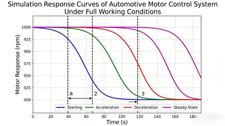
Results across 4 Typical Driving Conditions:
- Startup (0 → 1000rpm, 20N·m): Takes 0.35s, 3% overshoot, 0.5% steady-state error.
- Acceleration (1000 → 5000rpm, 50N·m): Finishes smooth transition in 1.2s with exact tracking.
- Steady-State (5000rpm, 50N·m): Speed fluctuation ≤±5rpm, torque ripple ≤±1N·m.
- Regenerative Braking (5000 → 0rpm, -40N·m): Safe deceleration in 1.5s with stable energy recovery.
At Dowway Vehicle, using this exact simulation framework cut our R&D cycle by over 30% and improved motor operational efficiency by >5%.
6. Frequently Asked Questions in Vehicle Control System Design
Q1: How should a vehicle dynamics model be constructed for control design?
Short Answer: It depends on the maneuver. Use kinematic models for slow speeds, bicycle models for handling, and full models for final testing.
Explanation: Engineers pick mathematical models based on the use case. Kinematic models handle geometric motion (like parking). The Bicycle Dynamic Model simplifies the car to just front and rear wheels, making it perfect for lateral control. Full vehicle models cover longitudinal, lateral, and vertical dynamics for rigorous simulation validation.
Q2: How can vehicle stability and handling be ensured?
Short Answer: Systems like Electronic Stability Control (ESC) brake individual wheels automatically to stop skidding.
Explanation: Lateral dynamics control handles stability. ESC detects when a driver loses steering traction. It automatically applies exact braking force to specific wheels to correct oversteer or understeer. This direct yaw-moment control keeps the car stable on the road.
Q3: What control algorithms are most commonly used in vehicle control systems?
Short Answer: The industry uses PID for basics, Robust control for hardware uncertainty, and Model Predictive Control (MPC) for autonomous driving.
Explanation: Classical control (PID, Linear Quadratic Regulator) handles linear systems well. Robust and Nonlinear Control (Sliding Mode Control, H-infinity) manages unpredictable physical changes. Model Predictive Control predicts future behavior to calculate perfect inputs within strict constraints, making it the top choice for path tracking today.
Q4: How can nonlinearities and uncertainties in vehicle dynamics be handled?
Short Answer: Engineers combine state estimation filters with adaptive controllers to adjust to sudden physical changes automatically.
Explanation: Real vehicles deal with tire saturation and changing road friction. Systems use tools like the Extended Kalman Filter to estimate states we cannot measure directly (like sideslip angle). Adaptive controllers take this data and adjust to external shocks, keeping the car stable even if the base model is imperfect.
Q5: How can multiple vehicle subsystems be controlled together?
Short Answer: Vehicles use an Integrated Vehicle Dynamics Control (IVDC) architecture to act as a central brain.
Explanation: IVDC coordinates parts that might otherwise fight each other. It links Anti-lock Braking (ABS), Traction Control, ESC, and Active Suspension. This smart allocation of commands across multiple actuators maximizes safety, maneuverability, and energy efficiency at the same time.
Bonus: The MPC Vehicle Control Design Workflow
Model Predictive Control (MPC) is the standard for advanced vehicle control. Engineers follow a 4-step workflow to build it:
- Plant Modeling: Define the mathematical model of the vehicle to predict future states over a set time horizon.
- Constraint Definition: Set strict mathematical limits for physical hardware (maximum steering angle, tire friction limits).
- Cost Function Formulation: Create a math target to minimize errors (like drifting out of a lane) while stopping harsh control inputs to keep passengers comfortable.
Real-Time Optimization: The controller solves this math problem at every step, applies the first action, and recalculates everything again in the next loop.
