

< Back to Performance Development
Quick Summary for Engineers
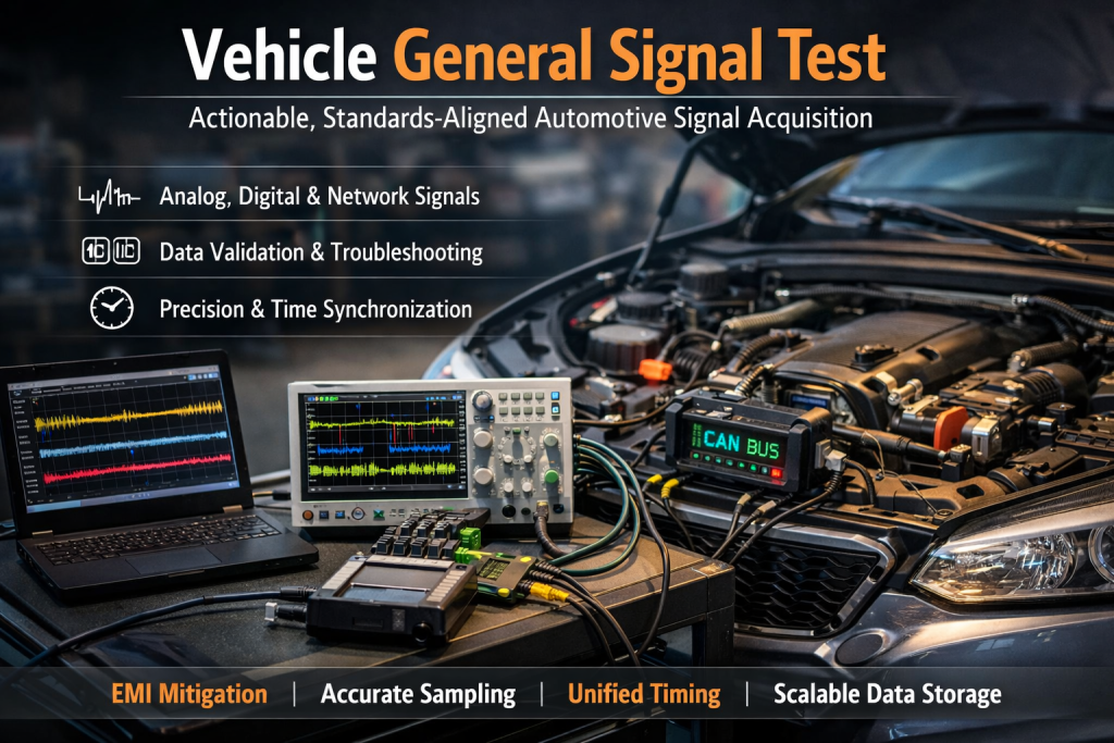
- What this page covers: End-to-end automotive signal acquisition and validation—analog, digital, and in-vehicle network signals—with practical implementation checklists, common failure modes, and engineering fixes.
- Why it matters: Sensor-rich intelligent vehicles rely on accurate, time-aligned data for monitoring, diagnostics, performance optimization, ADAS, and EV battery safety.
- Key success factors: Signal conditioning, correct sampling, robust EMI mitigation, nanosecond-grade time synchronization, and scalable storage strategies.
- What "Vehicle General Signal Test" Means in Modern Vehicles
- Core Requirements
- Layered Architecture of an Automotive Signal Data Acquisition System
- Signal Taxonomy Used in Automotive Testing
- Analog Signal Acquisition
- Digital Signal Acquisition
- Bus Signal Acquisition
- Key Engineering Challenges and Solutions
- Application Scenarios
- Future Trends
- Practical Checklist
- FAQs
- Final Thoughts
What “Vehicle General Signal Test” Means in Modern Vehicles
Modern vehicles integrate mechanical, electronic, and software systems. A vehicle general signal test validates how engineers capture, condition, digitize, timestamp, transmit, store, and preprocess signals so they can trust the data for design decisions.
High-end cars carry 50–100 sensors across the powertrain, chassis, body, and driving systems. These sensors stream continuous data: rotational speed, pressure, temperature, displacement, currents, switching states, PWM actuator commands, and network packets. Those signals enable:
- Vehicle state monitoring and performance optimization
- Fault diagnosis and predictive maintenance
- ADAS and autonomous driving perception
- Connected services (fleet monitoring, OTA decision support)
- EV battery management system (BMS) control
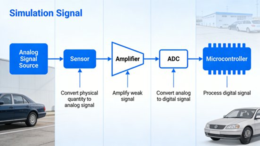
Acquisition acts as a controlled chain: physical quantity to electrical signal to digital signal. The goal is to keep the signal intact and time-aligned across all channels.
Core Requirements
A solid test plan survives harsh vehicle conditions and produces reliable data.
- Reliability: Systems must run under extreme temperatures (-40°C to 85°C), vibration, and high electromagnetic interference. Engineers use redundant critical channels and defensive designs to stop data loss.
- High Accuracy: Targets depend on the signal type. Rotational signals need tiny error margins for control tuning. Small drifts in temperature data trigger bad thermal management. For multi-sensor setups, time alignment matters as much as amplitude accuracy.
- Real-Time Performance: Control loops and ADAS need tight latency control—often near milliseconds—so the ECU acts fast enough to keep the car safe.
- Compatibility: Testing must support analog, digital, and bus inputs across various interfaces and suppliers.
- Scalability: As car architectures grow to include new sensors and higher bandwidths, acquisition platforms must scale their channel counts and precision.
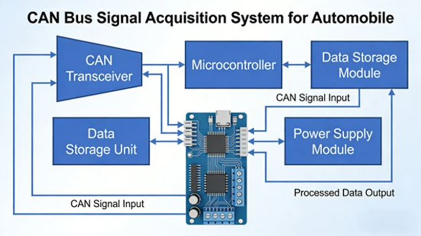
Layered Architecture of an Automotive Signal Data Acquisition System
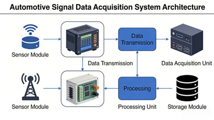
A practical system breaks down into five layers (bottom to top):
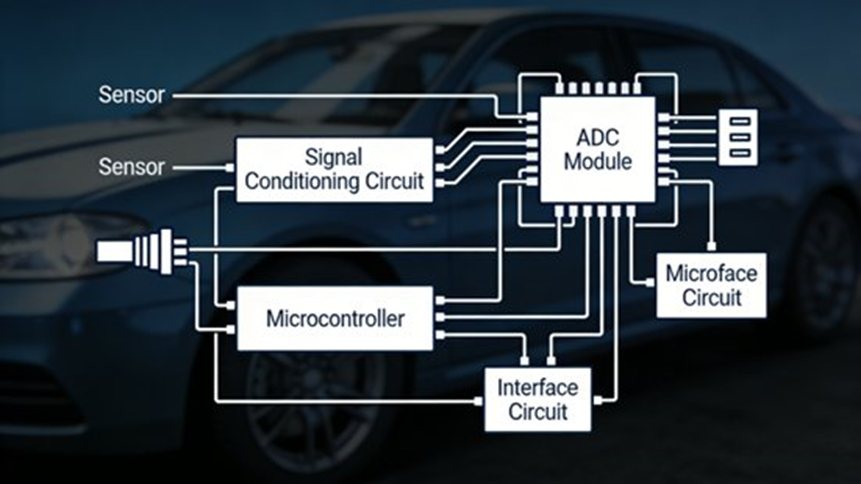
- Perception Layer (Sensors): Sensors change physical measurements (speed, pressure, temperature, position, current) into electrical outputs.
- Acquisition Layer (Conditioning + ADC + Controller): This layer turns raw electrical inputs into digital data through signal conditioning (filtering, amplification, isolation), ADC conversion, and capture control (using MCU/FPGA/DSP units).
- Transport Layer (In-Vehicle Networks / Wireless): Transports include CAN/CAN FD, LIN, FlexRay, and Automotive Ethernet for high-bandwidth time-sync networks.
- Storage Layer (Local + Cloud): Local storage uses SSDs or SD cards for fast raw logs. Cloud storage handles long-term retention, fleet analytics, and OTA workflows.
- Preprocessing Layer: Software cleans the data using noise reduction, timestamp synchronization, and outlier removal.
Signal Taxonomy Used in Automotive Testing
Automotive signals fall into three main types, each requiring different measurement strategies.
| Signal Type | Typical Examples | Main Risk | Key Capture Need |
| Analog (continuous) | Temperature, pressure, displacement, current | EMI/noise, weak amplitudes | Conditioning + correct ADC selection |
| Digital (discrete) | Switches, pulses, PWM, wheel/crank speed | Timing errors, missed edges | Edge capture + accurate time base |
| Bus (packetized) | CAN/LIN/FlexRay/Ethernet frames | Decode errors, overload, sync drift | Correct interface + decode config + synchronization |
Analog Signal Acquisition
Analog inputs track continuous physical states. Standard ranges fall between 0–5 V, 0–10 V, and 4–20 mA. They are weak and sensitive to noise, making conditioning mandatory.
Common automotive analog signals include engine coolant temperature, intake manifold pressure, throttle opening, and alternator output current. They are especially vulnerable to EMI from ignition systems, motors, and harness coupling.
Signal Conditioning: Filter, Amplify, Isolate
Filters (low-pass, high-pass, or band-pass) strip out interference while keeping the real dynamics. Many sensors output millivolt-level data, requiring amplification to match the ADC input range and cut quantization errors. Optical or magnetic isolation stops interference between modules.
ADC Selection
Typical automotive analog acquisition uses 12–16 bit ADCs. Sampling rates commonly fall around 100 Hz to 10 kHz. High-speed phenomena (like transient vibration or knock-related inputs) need 10 kHz or more to catch rapid changes.
Implementation Tips
Keep sensors close to the source to shorten harnesses and cut attenuation. Tune the gain and filter cutoff to the sensor’s output spectrum. For example, NTC thermistor temperature sensors need clean installation and resistance matching.
Digital Signal Acquisition
Digital inputs toggle between high and low states, including pulses and PWM. They resist amplitude noise better than analog lines but fail quickly if the timing is wrong. Common examples include crankshaft position pulses, wheel speed pulses, and brake switch states.
Capture Controllers and Timing
MCUs handle moderate speeds. FPGAs manage deterministic, high-resolution, multi-channel timing. DSPs fit when you need both capture and real-time processing.
Multi-channel digital capture demands tight timing. The sampling rate must comfortably exceed the signal frequency. For pulses or PWM, edge timestamping usually beats basic periodic sampling. Multi-channel setups rely on hardware clock sharing or precise timestamp alignment.
Implementation Detail
For Hall-type wheel-speed sensors, the physical gap matters. The sensor-to-tooth-ring gap must stay within a tight window (usually 0.5–1.0 mm). A larger gap causes missed pulses and bad speed data.
Bus Signal Acquisition
Bus traffic travels in packets containing identifiers, data bytes, and checksums. A single CAN frame packs multiple variables—like vehicle speed, engine speed, and gear position. Testing must capture the message, decode it, and unpack the variables.
- CAN/CAN FD: Runs across powertrain, chassis, and body networks, matching ISO standards for Classical CAN and CAN FD.
- LIN: Handles low-speed comfort and body control functions.
- FlexRay: Supports deterministic timing behavior for safety domains.
- Automotive Ethernet: Carries high-bandwidth camera or lidar streams and acts as the time-sync backbone.
Bus capture requires the right interface modules, protocol variants, bit rates, and decoding rules to map frames to variables correctly. Timestamps must align across different buses.
Key Engineering Challenges and Solutions
1. Electromagnetic Interference (EMI)
Motors, alternators, and ignition systems create EMI that distorts inputs, creating false fluctuations.
- Solutions: Hardware fixes include shielded harnesses, solid grounding, differential inputs, and power filtering capacitors. Software fixes use digital filtering and redundant capture. Also, physically separate acquisition hardware from strong EMI sources.
2. Time Synchronization Across Sources
Multi-channel capture can misalign timestamps. In intelligent driving, misaligned lidar and camera data distorts perception.
- Solutions: Fix this with a unified hardware clock source (like GPS/GNSS or high-stability oscillators) for nanosecond accuracy. Software algorithms can correct timestamps and compensate for delays. Network-based sync relies on IEEE 802.1AS (gPTP) for time-sensitive applications.
3. Multi-Source Signal Fusion
Multiple sensors output different formats, rates, and noise characteristics.
- Solutions: Normalize formats, units, and timestamps early. Apply fusion algorithms (like Kalman or Bayesian estimation) to correct data and handle redundancies. Use modular platforms that let you easily add sensors and configure them centrally.
4. Data Storage and Transmission at Scale
Intelligent driving sensors create massive data volumes (tens of MB/s).
- Solutions: A hybrid approach works best: local SSDs for raw data and cloud storage for long-term analytics. Compress data to shrink transfer sizes. Send safety and fault signals first based on rule logic. Set up ring buffers and rotate files by size or time (for example, at 10 GB or 30 minutes), writing to formats like PCAPNG or ROS2 bag.
Application Scenarios
- R&D and Vehicle Validation Testing: Collect speed, pressures, injection timing, and exhaust temperature for powertrain control tuning. Capture suspension displacement and steering angle for chassis stability.
- Fault Diagnosis and Predictive Maintenance: Real-time monitoring detects abnormal patterns like unusual RPM fluctuations. Historical trends track component wear. Modern workflows integrate standardized diagnostic services (UDS under ISO 14229-1).
- Intelligent Driving: ADAS needs synchronized perception (lidar/camera/radar) plus vehicle-state signals (speed, steering) and driver intent signals (pedal positions).
- EV Battery Management (BMS): BMS relies on the acquisition of voltage, current, temperature, SOC, and SOH for thermal safety protection and balancing control.
Future Trends
- Higher Precision and Real-Time Performance: Nanosecond-grade time alignment, higher sampling rates (>100 kHz), and 24-bit ADCs.
- Multi-Modal Fusion Capture: Unified platforms that capture analog, digital, bus, and perception data together.
- Intelligent Acquisition + Edge Computing: On-vehicle preprocessing cuts cloud bandwidth, lowers latency, and runs real-time anomaly detection.
- Cloud-Cooperative Acquisition: Vehicle-side collection combined with cloud-side analytics supports fleet-scale monitoring and control strategy upgrades.
- Automotive-Grade Integrated Modules: Packing conditioning, ADC, bus decode, logging, and time sync into smaller, low-power, rugged modules.
Practical Checklist
A) Plan
- Define signals: analog, digital, bus, perception.
- Set sampling and timing targets per signal class.
- Identify safety-critical channels for redundancy.
- Define acceptance criteria (accuracy, dropouts, latency, sync error).
B) Build
- Analog: pick correct conditioning (gain/filter/isolation) and ADC specs.
- Digital: choose edge capture vs sampling; ensure stable time base.
- Bus: confirm protocol variants, bit rates, decoding database mapping.
- Time sync: define clock strategy (hardware clock + gPTP alignment).
- Storage: set ring buffer rotation policy (size/time), plus local/cloud division.
C) Validate
- Run calibration checks and reference comparisons.
- Run cross-signal sanity checks (e.g., wheel speed vs vehicle speed estimate).
- Monitor timestamp continuity and multi-channel alignment.
- Run EMI checks during high-load operation (alternator/inverter/ignition stress).
FAQs
What is “Vehicle General Signal Testing” in modern car development?
It validates electrical and communication signals across the vehicle’s network (CAN, CAN FD, LIN, Ethernet). Engineers ensure that every ECU correctly reads, transmits, and processes signals like wheel speed or battery voltage using SIL (Software-in-the-Loop) and HIL (Hardware-in-the-Loop) testing.
How do engineers handle Signal Integrity issues?
Engineers use oscilloscopes and eye diagram analysis to find noise, jitter, and attenuation. CAN physical layers follow ISO standards like 11898-1. Environmental testing often uses LV 124 guidelines for 12V systems.
What are the most common faults found during vehicle signal diagnostics?
Communication errors (dropped packets), sensor drift, grounding problems, parasitic power draw, and data corruption.
What are the industry standards for vehicle signaling?
Common references include SAE J1939 for heavy-duty networks, ISO 14229-1 (UDS) for diagnostics, SAE J3016 for driving automation levels, and IEEE 802.1AS (gPTP) for time synchronization.
How does signal testing change for EVs and smart cars?
EVs introduce high-voltage rules, so testing must check isolation and EMI coupling between HV systems and 12V networks. For smart cars, testing shifts to high-bandwidth data (Automotive Ethernet) and strict time synchronization.
What is the main difference between testing analog signals and bus signals?
Analog testing depends on conditioning and ADC choices (filtering, gain, isolation, sampling rate). Bus testing depends on interface setups, decoding rules, and network time alignment.
Final Thoughts
A strong signal program focuses on trustworthy data under heavy noise, vibration, and high throughput. Engineers who condition inputs correctly, capture timing accurately, sync clocks via gPTP, and manage storage will build a solid foundation for R&D validation, diagnostics, intelligent driving, and EV safety.
