

< Back to Performance Development
Author: Johnny Liu, CEO at Dowway Vehicle
Published: March 3, 2026
Reading Time: Approx. 15 minutes
Author’s Note: At Dowway Vehicle, we have spent decades solving automotive body manufacturing problems on the factory floor. A modern vehicle roof is a hybrid marvel. The outer skin relies on precision stamping, while the supporting structural frames often use vehicle roof extrusion. In this guide, I want to share exactly what causes stamping deformation, how we fix these defects, and answer the top questions we get about roof extrusion technologies to help you achieve Class-A automotive quality.
- 1. Introduction: The Real Challenges of Vehicle Roof Manufacturing
- 2. Core Process Flow and What Makes Roofs Deform
- 3. Four Common Defects and Their Root Causes
- 4. Smart Detection and FEA Simulation Methods
- 5. A 5-Step Strategy for Defect Control
- 6. Real-World Case Study: Fixing a DC06 Steel Roof
- 7. Frequently Asked Questions: Vehicle Roof Extrusion
- What is "vehicle roof extrusion" in automotive manufacturing?
- Why do automakers rely on aluminum extrusion for roof components?
- Which specific roof parts use extruded profiles?
- What are the real manufacturing challenges with vehicle roof extrusion?
- How do extruded roof parts help Electric Vehicles (EVs)?
- 8. Final Thoughts and What's Next
1. Introduction: The Real Challenges of Vehicle Roof Manufacturing
Stamping is a core process in automotive body manufacturing because it works fast and keeps costs down in large-scale production. The vehicle roof is a large, curved part that requires strict attention to detail. It must meet exact aerodynamic shapes, fit perfectly with side panels and windshields, and stay rigid enough to handle wind loads and physical bumps.
Vehicle roof outer panels usually consist of high-strength steel or aluminum alloy sheets between 0.6 and 1.2mm thick. Stamping these thin metal sheets causes intense plastic deformation. Because so many different variables cross paths on the press line, defects happen often. Factory data shows that roof stamping deformation makes up over 30% of all outer panel stamping defects. Solving these issues directly saves money and prevents assembly headaches down the line.
2. Core Process Flow and What Makes Roofs Deform
The Standard Multi-Step Process
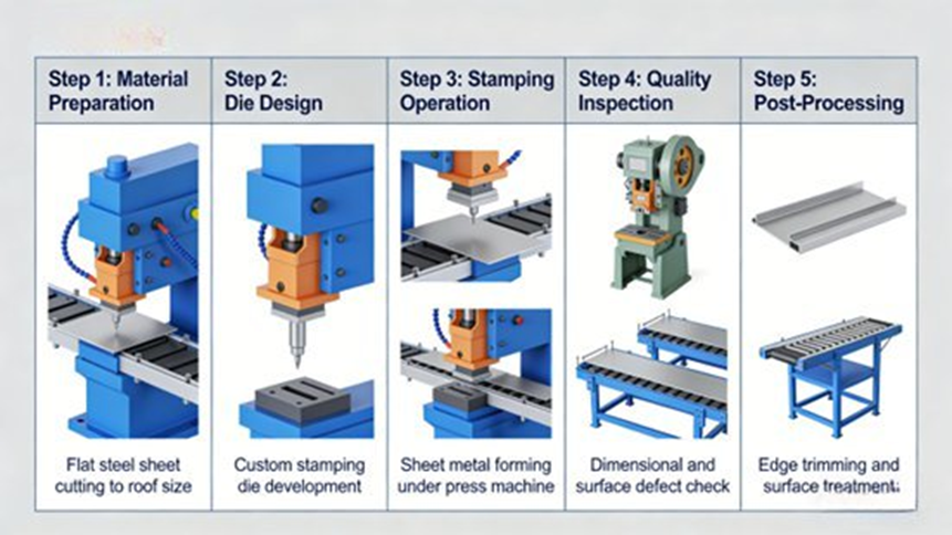
[Image Placeholder: Automotive roof stamping process flow diagram]
A typical stamping line follows this flow: Raw Material Inspection → Blanking → Cleaning & Oiling → Drawing (OP10) → Trimming & Piercing (OP20/OP30) → Restriking/Flanging (OP40) → Surface Inspection → Packaging. We mostly see deformation problems pop up during the drawing (OP10) and restriking (OP40) stages.
5 Key Characteristics of Roof Deformation
- Uneven Stress: Complex surface transitions and tight corners cause irregular stress and strain, leading straight to stress concentration.
- Thin Material Instability: When working with metal ≤1.2mm thick, the low rigidity means the sheet buckles easily under tangential compressive stress.
- High Springback Risk: When the press lifts, the metal releases residual elastic stress and bends out of shape. We see this often with high-strength steels that have a high yield-to-tensile ratio.
- Strict Class-A Surface Rules: Automakers tolerate zero scratches, dents, or wavy lines on a roof.
- Coupled Variables: Defects rarely come from just one bad setting. Material properties, die precision, process speeds, and equipment health all interact to cause trouble.
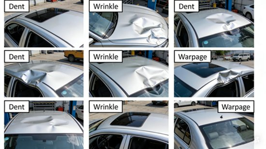
3. Four Common Defects and Their Root Causes
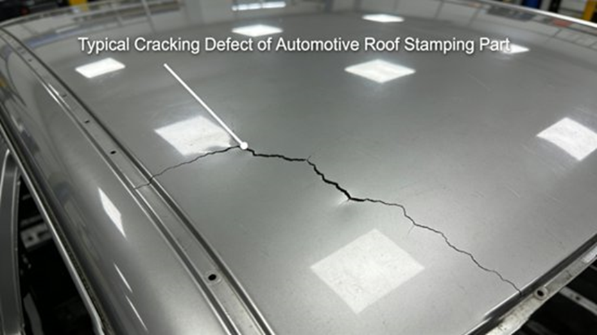
3.1 Cracking (Tearing)
[Image Placeholder: Typical cracking defect]
We usually spot cracking during the drawing stage around sunroof openings, windshield joints, and tight corners where the strain simply breaks the material’s physical limit.
- Causes: Using materials with high yield-to-tensile ratios or poor elongation; designing punch/die radii too small; applying too much blank holder force (BHF); running the draw speed too fast; or pushing the surface strain past the Forming Limit Curve (FLC).
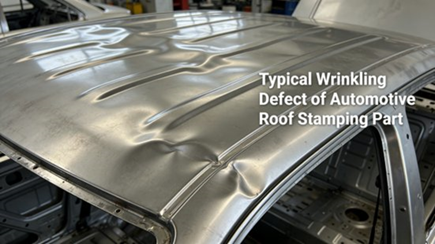
3.2 Wrinkling
[Image Placeholder: Typical wrinkling defect]
Wrinkling creates wavy ridges along the flange area, sidewalls, or shallow drawing parts.
- Causes: Material flowing too fast and piling up; setting the BHF too low or unevenly; designing drawbeads with weak resistance; leaving too much die closure clearance; or forgetting to add exhaust holes, which lets trapped air push back against the metal.
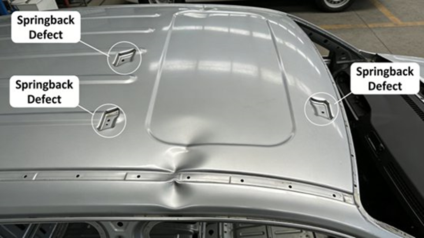
3.3 Springback
[Image Placeholder: Typical springback defect]
Springback happens when the metal tries to return to its original flat shape after leaving the die. It warps the part and ruins assembly tolerances.
- Causes: High elastic modulus materials; ignoring reverse springback compensation during die design; leaving wide punch/die gaps; using weak BHF during drawing (which prevents full plastic deformation); or applying weak pressure during the restrike phase.
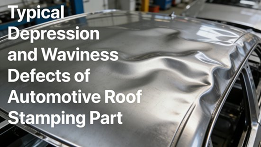
3.4 Surface Depressions & Waviness
[Image Placeholder: Depression and waviness defects]
These are tiny surface flaws—usually just 0.1 to 0.5mm deep—but they ruin the final paint job.
- Causes: Uneven stress between the center and the edges of the roof; tiny wear marks or poor polishing on the die surface; press machines with bad slider parallelism; or patchy lubrication that changes friction mid-stroke.
4. Smart Detection and FEA Simulation Methods
4.1 Finding the Flaws
- Surface Quality: My team relies on visual checks, oil stone polishing (the absolute best manual way to find micro-dents), and automated optical systems like Zeiss or ARGUS to map strain accurately.
- Dimensional Accuracy: We use checking fixtures for quick batch testing, Coordinate Measuring Machines (CMM, accurate to 0.01mm), and Blue/White light 3D scanners to compare point-cloud data against the original CAD file.
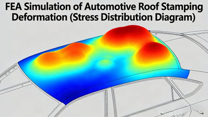
4.2 Finite Element Analysis (FEA) Simulation
[Image Placeholder: FEA simulation stress distribution diagram]
Before cutting any steel for dies, we use software like AutoForm, DYNAFORM, or UG/NX. We plug in boundary conditions (BHF, speed, friction) to simulate the stamping hit. FEA builds a Forming Limit Diagram (FLD) to predict cracking and shows us exactly where to fix die geometry before we ever run a physical trial.
5. A 5-Step Strategy for Defect Control
Step 1: Material Selection & Control
Pick dedicated stamping steels like DC04 or DC06 with good yield-to-tensile ratios. Check incoming batches closely for exact thickness, yield strength, and elongation. Always wash the blanks to remove dirt before stamping.
Step 2: Die Design Fixes
- Radii & Clearances: Push punch and die radii to ≥5mm. Keep die clearance steady at 1.05 to 1.1 times the sheet thickness.
- Drawbeads: Rely on half-round or trapezoidal drawbeads to grab and hold the material smoothly.
- Compensation & Exhaust: Apply FEA-guided reverse springback compensation directly into the CAD model. Drill exhaust holes in deep pockets to let air escape.
- Surface & Cooling: Polish dies until surface roughness hits Ra ≤ 0.8μm. If you run difficult alloys, drill cooling channels to keep the die temperature between 20°C and 50°C.
Step 3: Dialing in the Process Parameters
- Segmented BHF: Use dynamic hydraulic cushions. Set the BHF to roughly 5% to 10% of the tensile strength multiplied by the blank holder area, and change the pressure dynamically as the punch drops.
- Drawing Speed: Run standard steel at 100 to 200 mm/s. Slow down to 50 to 150 mm/s for high-strength steel or aluminum.
- Lubrication: Spray oil evenly. Keep the coating weight between 5 and 10 g/m².
- Restriking: Hit the part with a restriking pressure equal to 30% to 50% of your initial drawing pressure.
Step 4: Keep the Equipment Honest
A sloppy press ruins a perfect die. Calibrate machines strictly:
- Slider parallelism deviation: ≤ 0.02 mm/m
- Table flatness deviation: ≤ 0.03 mm/m
- Stroke precision deviation: ≤ 0.01 mm
- Pressure fluctuation: ≤ ±5%
Step 5: Floor Management
Follow standard operations and use a “Three-Inspection” routine (operator check, peer check, expert check). Keep the stamping workshop temperature stable between 18°C and 25°C and the humidity at 40% to 60% so the metal behaves predictably.
6. Real-World Case Study: Fixing a DC06 Steel Roof
The Problem
At Dowway Vehicle, we ran a sedan roof using 1.0mm DC06 cold-rolled steel and hit a painful 15% defect rate. The corners near the sunroof tore open. The center of the roof had wavy ripples 0.2 to 0.4mm deep. Worse, the rear windshield joint bent out of shape with 1.2 to 1.8mm of springback, failing the tight ≤0.8mm assembly tolerance.
Digging into the Root Causes
- Dies: The toolmakers cut the radii to only 3mm. They skipped springback compensation entirely, and the center drawbead failed to grip the metal tight enough. Die roughness measured a poor Ra=1.2μm.
- Process: The press operator used a static 800kN BHF from top to bottom and dropped the punch too fast at 220 mm/s. The corners near the sunroof ran dry with bad oiling.
- Equipment: We measured the press slider parallelism at 0.03 mm/m, which threw the whole hit off balance.
How We Fixed It
- Die Upgrades: We ground the radii open to 6mm, machined a 1.5mm reverse springback compensation into the rear joint, drilled four φ8mm exhaust holes, and repolished the steel to Ra ≤ 0.8μm.
- Process Tweaks: We programmed a segmented BHF curve (600kN → 900kN → 700kN), slowed the ram down to 150 mm/s, and set the automated sprayers to a flat 8 g/m² of oil.
- Press Maintenance: We calibrated the slider parallelism back to a tight 0.015 mm/m.
The Results
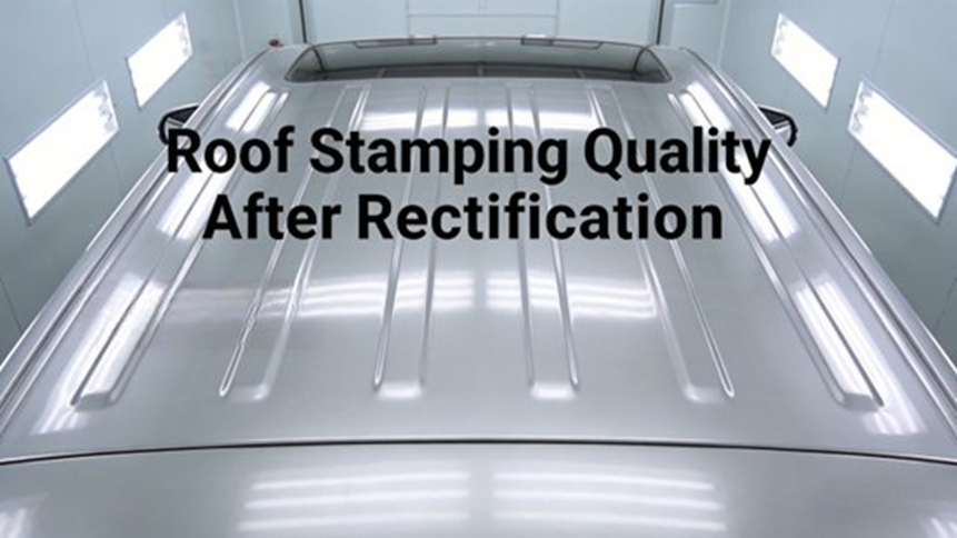
We ran a 500-piece trial followed by a 3,000-piece production run. Sunroof cracking dropped to zero. Center waviness vanished below 0.1mm. Springback locked in between 0.5 and 0.7mm. Our total defect rate settled securely under 1.5%, saving heavy scrap costs and keeping the assembly line moving.
7. Frequently Asked Questions: Vehicle Roof Extrusion
While stamping shapes the large outer skin, a vehicle’s structural skeleton relies heavily on extrusion. Our engineering team often gets questions about how we use extruded parts. Here are the clear answers.
What is “vehicle roof extrusion” in automotive manufacturing?
Vehicle roof extrusion means pushing heated aluminum (or other metals) through a shaped die to create continuous structural profiles. We use these precise metal shapes to build roof rails, headers, trims, and inner support frames. Automakers favor aluminum because it gives engineers a massive strength-to-weight ratio, refuses to rust, and allows for highly customized shapes.
Why do automakers rely on aluminum extrusion for roof components?
Engineers choose aluminum extrusions for roofs because these parts:
- Cut overall vehicle weight, which saves fuel and drops emissions.
- Keep the cabin stiff and safe during rollover crashes.
- Let designers combine multiple mounting channels and shapes into one single, clean profile.
- Give superior rust protection for exterior parts exposed to weather.
Which specific roof parts use extruded profiles?
We put extruded profiles to work across several roof areas:
- Roof rails and headers: The strong tracks on top of the car that hold luggage boxes.
- Support frames and guides: The hidden, complex tracks that let panoramic sunroofs slide open and closed smoothly.
- Trims: Clean metal finishes that also seal out water and wind.
- Reinforcement beams: Hidden cross-members tying the roof to the side pillars to stop the car body from twisting.
What are the real manufacturing challenges with vehicle roof extrusion?
Making automotive-grade extrusions is tough work. On the factory floor, we deal with:
- Tight tolerances: Cars require exact dimensions, so parts fit together perfectly without rattling.
- Complex dies: Designing the steel dies to force hot aluminum into intricate, multi-hollow shapes takes serious engineering skill.
- Weight vs. Strength: Trimming the wall thickness to save weight while still passing brutal global crash tests.
- Volume stability: Keeping the extrusion presses running day and night without losing dimensional accuracy.
How do extruded roof parts help Electric Vehicles (EVs)?
Extruded roof parts perfectly match what modern EV designs need. They help by:
- Shedding weight: Lighter roofs make up for heavy floor batteries, which adds real miles to the driving range.
- Combining parts: One clever extruded shape can replace three separate stamped brackets, making the assembly line much simpler.
- Staying green: Aluminum melts down and recycles easily, matching the environmental goals of building EVs.
8. Final Thoughts and What’s Next
Building a flawless vehicle roof takes a tight grip on material science, die precision, and daily machine maintenance. Whether you are stamping the outer skin or extruding the inner rails, ignoring tiny details leads to massive defect rates.
Looking forward, the auto industry must figure out how to stamp and extrude newer, lighter materials like advanced high-strength steels and composites. We will also see more factories relying on smart, real-time press monitors to catch bad hits and adjust parameters on the fly, stopping defects before they ever reach the inspection table.
