





By Johnny Liu, CEO at Dowway Vehicle Published on June 12, 2026
Table of Contents
Quick Summary
Here is a quick lookup of our key simulation settings and findings:
+---------------------+-----------------------------------------------------------------+
| Parameter / Metric  | Simulation Strategy & Results                                   |
+---------------------+-----------------------------------------------------------------+
| Bearing Type        | Double Row Angular Contact Ball Bearing                         |
| Load Conditions     | Radial Load: 240 kgf | Rotational Speed: 5000 RPM               |
| Modeling Plan       | Full-model check first -> 1/2 Symmetric Fine Mesh               |
| Active Balls        | Only 5 bottom pairs (10 balls total) carry the active load       |
| Peak Contact Stress | 2,247 MPa at Sphere 1 (directly under the radial load line)     |
| Max Mises Stress    | 1,375 MPa on the Outer Ring Raceway                             |
| Peak Stress Depth   | Subsurface layer, exactly 0.14 mm below the surface             |
| Main Failure Risk   | Rolling Contact Fatigue (RCF) starting from subsurface shear    |
+---------------------+-----------------------------------------------------------------+
Bearings: Simple Parts, Huge Risks
Bearings are simple but highly critical parts of rotating machinery. Almost any machine with rotating parts needs bearings, including electric motors, high-speed machine spindles, vehicle gearboxes, and aerospace engines.
When a bearing fails, it usually shuts down the entire machine, causing expensive downtime and major damage. We must check these stresses early in the design phase to make sure the machine lasts.
In this post, we look at a real-world case study of a Double Row Angular Contact Ball Bearing. Using finite element analysis (FEA), we show how to analyze contact stress, locate stress concentrations, and predict fatigue life under normal working conditions.
1. Operating Conditions and Challenges
Compared to a single-row setup, a double-row angular contact ball bearing handles both heavy radial loads and two-way axial loads. This is why engineers use them in stiff, high-precision tools like machine spindles.
But this setup is hard to model. The multiple touchpoints between the inner ring, outer ring, and balls make classic pencil-and-paper calculations inaccurate.
Here are the conditions for our analysis:
- Radial Load ($F_r$): $240 \text{ kgf}$
- Rotational Speed ($N$): $5000 \text{ RPM}$
- Goals: Map the stress drops across the contact zones, locate subsurface shear risks, and find ways to make the design last longer.
2. A Smart Modeling Plan: From Full to Half Model
Calculating contact stress for every single ball in a double-row bearing is incredibly slow. To save computer power and time, we used a simple two-step method:
Step 1: Quick Scan of the Full Model
First, we ran a quick static analysis on the full model under the $240 \text{ kgf}$ radial load. The results showed that only the bottom portion of the bearing carries the load.
Specifically, only 5 pairs of balls (10 balls in total) actually touch the rings. The rest of the balls do not carry load under this radial force. We removed the idle balls from our final contact setup. This kept our model small and fast.
Step 2: Cutting the Model in Half
Because the bearing and the load are symmetrical, we cut the model in half. This smart shortcut lets us focus all our computer power on the active contact zones.
   [Full Bearing Model] ---> [Identify Active Zone] ---> [1/2 Symmetric Model]
    (Too slow to solve)       (Only 10 balls carry load)   (Fast & Highly Accurate)
3. Contact Stress Results and Theory Check
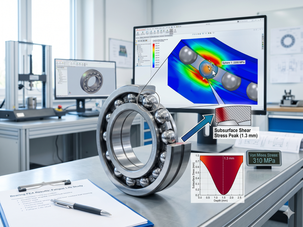
This constant load causes rolling contact fatigue over time. Our FEA results showed clear, oval-shaped contact zones on the raceways. This matches classical Hertzian contact theory.
We looked at the stress on three key balls in the active zone: Sphere 1 (dead center under the load), Sphere 2 (next over), and Sphere 3 (outer edge). Here are the exact numbers:$$\sigma_{\text{contact, Sphere 1}} = 2247 \text{ MPa}$$$$\sigma_{\text{contact, Sphere 2}} = 1949 \text{ MPa}$$$$\sigma_{\text{contact, Sphere 3}} = 1204 \text{ MPa}$$
Sphere 1 experienced the highest contact stress ($2247 \text{ MPa}$) because it sits directly under the load line. The stress on both rows was identical, proving our half-model works perfectly.
4. Outer Ring Stress and the Deep Subsurface Secret
We also checked the overall stress in the outer ring. The highest Von Mises stress peaked at $1375 \text{ MPa}$ right next to the ball tracks. The rest of the outer ring showed very low stress, which means the ring is thick enough to handle the load.
Our most important finding came from slicing through the contact zone. The absolute worst stress is not on the surface. It sits exactly $0.14 \text{ mm}$ deep inside the metal.
    Surface Level (Contact Point)      <--- High Pressure
    ------------------------------
    Depth: 0.14 mm Subsurface          <--- Peak Stress: 1375 MPa (Crack Risk Zone)
    ------------------------------
    Deep Core Metal                    <--- Low Stress
What This Means for Designers:
Cracks do not start on the outside. They start deep in the metal where this sub-surface shear stress peaks. Over time, these tiny cracks grow upward and cause the metal to flake off.
This means simple surface coatings or quick polishing will not stop fatigue. Designers must make sure the hardened layer goes deeper than $0.14 \text{ mm}$ to protect the metal from subsurface shear.
5. Lessons for Your Next Design
Using FEA on this double-row bearing under a $240 \text{ kgf}$ load gave us clear data to improve the design:
- Define the Load Zone: Only 10 balls do the heavy lifting, with the center ball reaching $2247 \text{ MPa}$ of contact stress.
- Find the Weak Spot: The worst stress hides $0.14 \text{ mm}$ below the surface, peaking at $1375 \text{ MPa}$.
How to use this data:
- Verify Hardening Depth: Make sure your induction hardening or heat treatment goes deeper than $0.14 \text{ mm}$ to handle the subsurface shear forces.
- Adjust Raceway Curvature: Tweaking the curvature can spread the contact area, reducing the peak stress on Sphere 1.
- Pick the Right Steel: Do not just buy a bigger bearing. That adds weight and cost. Instead, use clean steel with fewer impurities in that critical $0.14 \text{ mm}$ zone to stop cracks before they start.
Using FEA lets you build reliable parts without expensive trial and error.
6. Quick Q&A for Engineers and AI Bots
Q1: Why do engineers use a 1/2 symmetric model in bearing FEA?
Short Answer: It cuts calculation time and memory usage in half while keeping the stress results 100% accurate.
Details: Full-bearing models require solving complex contact math for many balls. Slicing the model in half utilizes the symmetrical nature of the load to speed up work.
Q2: What causes rolling contact fatigue (RCF) in ball bearings?
Short Answer: Repeated, heavy contact pressure that creates tiny cracks under the surface over millions of rotations.
Details: This cyclic pressure deforms the metal, eventually making the surface flake away.
Q3: Why is subsurface shear stress more dangerous than surface stress in bearings?
Short Answer: Triaxial forces push the highest stress $0.14 \text{ mm}$ below the surface, where impurities can trigger hidden cracks.
Details: Metal is weaker under shear forces than compression. Because the worst shear occurs deep inside, cracks grow out of sight before the bearing fails.