





- Author: Johnny Liu, CEO at Dowway Vehicle
- Published Date: June 26, 2026
- Read Time: 8 mins
- Category: Hardware Engineering / Circuit Simulation / Model-Based Design
Table of Contents
Executive Summary
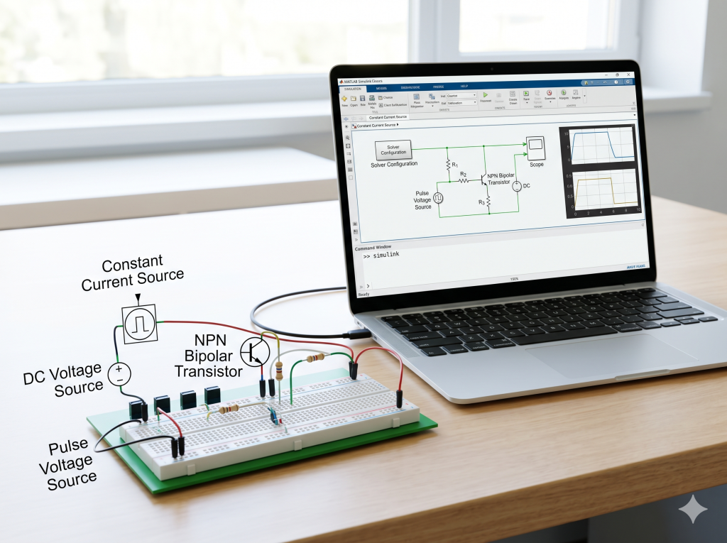
Quick Takeaway: While standard SPICE tools like LTspice and PSpice work well for basic circuit checks, MATLAB Simulink (via Simscape) gives hardware engineers a major advantage: you can build custom models straight from datasheet parameters and run Hardware-in-the-Loop (HIL) testing. This guide walks you through setting up a simple Constant Current Source in Simulink. We cover essential parts like the Solver Configuration, choosing the faster standard NPN Bipolar Transistor over the SPICE option, and cleaning up your workspace.
1. Beyond Academia: MATLAB & Simulink in Real-World Engineering
Many new engineers think MATLAB is just for university research or math papers. But in real-world industries—especially in automotive electronics, electric vehicles (EVs), and control systems—it is a heavy-duty workhorse.
In my daily work leading engineering teams, we use MATLAB’s broad range of features for:
- Writing and testing algorithms.
- Analyzing data and running calculations.
- Designing control systems and processing signals.
- Simulating physical hardware and plotting results.
Yes, MATLAB is a massive, heavy program. You need a fast computer to run it well. But the built-in toolboxes are incredibly useful. The tools I use most are Simulink (for physical and logical simulation) and the Antenna Designer toolbox, along with basic numerical calculations and custom plots.
Instead of generic introductions, let’s look at how to build a working Constant Current Source Circuit in Simulink. I will highlight the major engineering choices and setup steps you need to know.
2. Opening Simulink & Setting Up Your Workspace
How to Launch Simulink via Command Line
To save time, avoid clicking through heavy visual menus. I open the start page directly by typing this command into the MATLAB Command Window and pressing Enter:
simulink
This brings up the Simulink start screen immediately, where you can open a blank model and save your project file.
Fast Component Search (Type-to-Insert)
Once your workspace is open, do not waste time browsing the library tree. You can find and place components instantly with the Type-to-Insert shortcut:
- Double-click on any empty space on the canvas.
- Type the name or shortcut of the part (for example, type “R” to bring up a Resistor).
- Key Choice: Because we are building a physical circuit, make sure you select components from the physical domain (Simscape / Foundation Library / Electrical) rather than standard Simulink signal blocks.
3. Selecting Components: Transistor Simulation Speed and Power Sources
To build our Constant Current Source, we must pick our parts carefully.
NPN Bipolar Transistor vs. SPICE NPN
When you search for a transistor, Simulink gives you two main options:
- NPN Bipolar Transistor (Simscape standard model)
- SPICE NPN (SPICE-compatible model)
To read the official documentation for both parts, you can check these MathWorks pages:
? Quick Tip: For my simulations, I always use the standard NPN Bipolar Transistor. It uses simplified math that runs much faster while keeping the accuracy we need for general circuit testing.
Power Sources & Ground
To get the circuit running, add these parts to your canvas:
- DC Voltage Source: This gives you your main supply voltage.
- Pulse Voltage Source: This acts as your control signal to turn the circuit on and off.
- Electrical Reference: This is your zero-potential ground (0V). Just like any SPICE engine, a physical simulation cannot calculate node formulas without a defined ground reference point.
4. The Essential Link: Solver Configuration
If you try to run an electrical simulation in Simscape without a solver, MATLAB stops immediately and shows an error. You must place the Solver Configuration block on your schematic.
       [ DC Source ] ───┐
                        │
   [ Pulse Source ] ───[ Transistor Circuit ] ─── [ Electrical Reference (0V) ]
                               │
                    [ Solver Configuration ]
Why is the Solver Configuration Block Mandatory?
Standard signal-flow diagrams calculate simple step-by-step math formulas. Physical circuits are different; they rely on simultaneous equations where energy is conserved. The Solver Configuration block is the math engine. It sets the numerical solver options, error limits, and step sizes needed to translate your circuit paths into equations that MATLAB can solve.
5. Wiring, Measuring, and Adjusting Your Scope
Once all your parts are on the canvas, connect them by dragging lines between their electrical terminals to form a closed physical loop.
Measuring Circuit Values
To see the current and voltage levels in our constant current source:
- Place a Scope block on your canvas.
- Remember that a Scope cannot connect directly to Simscape physical connection points. You must use a Probe block along with your Scope. The probe measures physical values (like branch current or node voltage) and changes them into standard signals that the Scope can read.
Cleaning Up Your Scope Display
By default, the Scope display can look messy if you are checking several signals at once. To fix this:
- Double-click the Scope block to open the viewing window.
- Go to the top menu bar and select: View -> Layout (视图 -> 布局).
- Here, you can change the grid layout to show your graphs in separate windows rather than piling them on top of each other.
- You can also open the settings to change line thickness, colors, and background styles to make your charts look clean.
6. Simulink vs. SPICE (LTspice & PSpice): A Direct Comparison
For quick circuit testing, most hardware designers use PSpice or LTspice. Here is how Simulink compares for professional work:
| Feature/Metric | MATLAB Simulink (Simscape) | Traditional SPICE (LTspice / PSpice) |
|---|---|---|
| Initial Learning Curve | Moderate (Need to understand physical domains) | Low (Standard schematic drawing) |
| Simulation Speed | Fast (Especially with standard physical models) | Depends on model complexity & limits |
| Custom Parameter Modeling | Excellent (Model directly from datasheet values) | Poor (Requires vendor-specific .lib files) |
| System-Level Integration | Industry Standard (Connects with thermal, motor, & control systems) | Poor (Mostly limited to electric circuits) |
| Hardware-in-the-Loop (HIL) | Supported (Can run on real-time hardware like Speedgoat) | Not Supported (Only runs on your desktop) |
The Real Value: Custom Parameter Modeling & HIL
Simulink can feel a bit slower to set up than LTspice or PSpice at first. But for complete system design, it offers two massive advantages:
- No SPICE model? No problem. With SPICE programs, if a manufacturer does not offer a
.spior.libfile for a transistor, you cannot simulate it accurately. In Simulink, you can set up physical parts yourself by typing in parameters straight from the manufacturer datasheet (like gate charge, on-resistance, or thermal limits). - Hardware-in-the-Loop (HIL) Testing: You can convert your Simulink circuit designs into real-time code and run them on hardware simulators. This lets you test physical control boards against a simulated circuit, saving massive amounts of time.
7. FAQ
Q1: Why does Simscape need an “Electrical Reference” and a “Solver Configuration” when standard Simulink does not?
Answer: Simscape uses physics equations where energy flows both ways, rather than simple one-way mathematical signals.
Standard Simulink blocks run on straightforward input-output math ($y = f(x)$). Simscape simulates real physical connections. To solve these equations, the computer needs a zero-voltage starting reference point (the ground/Electrical Reference) and a dedicated solver block to calculate physical states.
Q2: Why is the standard “NPN Bipolar Transistor” block faster than the “SPICE NPN” block?
Answer: The standard model uses simplified, ideal physics equations, while the SPICE version runs complex non-linear formulas.
The standard Simscape transistor skips minor physical details to give you fast results during system testing. The SPICE NPN block tries to match the exact physical behavior from SPICE files, calculating tiny capacitance shifts at every single step. This extra math slows down your simulation.
Wrap Up
Using MATLAB Simulink for hardware simulation helps you look beyond small circuit components and focus on how your entire system works together. While setting up solvers, grounds, and probes takes a few extra steps compared to traditional SPICE tools, the ability to build models from datasheet specs and run real-time hardware tests makes it an incredibly valuable skill.
Have you run into slow simulation speeds with SPICE models in Simulink? Let me know how you solved it in the comments below!