





By Johnny Liu, CEO at Dowway Vehicle Published on June 29, 2026
Table of Contents
1. Introduction: The Shift in Vehicle Dynamics
As smart cars grow rapidly, chassis control is moving past old mechanical limits. We have entered a new era of active, software-defined control.
For decades, cars relied almost entirely on Front Wheel Steering (FWS). While functional, FWS forces engineers to choose between low-speed agility and high-speed stability.
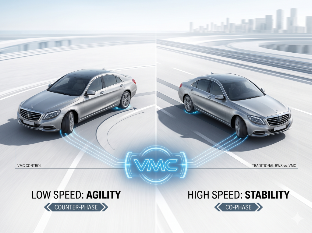
To fix these issues, engineers created Rear Wheel Steering (RWS). Turning the rear wheels active improves low-speed turning and high-speed stability.
[Traditional FWS] ───► Compromise between Low-Speed Turn Radius & High-Speed Stability
[Early Gen RWS]  ───► Rigid, Fixed-Ratio "Low-Speed Counter / High-Speed Co-Phase" Control
[VMC RWS]        ───► Dynamic, Compliant Virtual Spring-Damper Self-Adaptive Regulation
However, most current production RWS systems still rely on rigid, fixed-ratio, and passive control setups. They simply turn the rear wheels opposite to the front wheels at low speeds (counter-phase) and in the same direction at high speeds (co-phase).
These settings use fixed maps. They cannot adapt to real-time vehicle body movement, tire-road grip changes, or complex driving situations. Under limit handling or emergency moves, these rigid systems often suffer from steering lag, body wobble, and path deviation.
Vehicle Motion Control (VMC) coordination algorithms solve this. As a next-generation control setup, VMC discards traditional rigid, position-based loops. By building a Virtual Spring-Damper Dynamics Model, VMC actively regulates the rear wheel steering angle, response rate, and actuator force.
We will look at the technology, core math, pros, cons, and future of VMC.
2. Technical Background: Why Traditional RWS PID Control Fails
Steering system optimization centers around a simple conflict: low-speed agility versus high-speed stability.
Traditional vehicles rely only on FWS. Consequently, large SUVs and luxury sedans feel clumsy when parking or performing U-turns in tight spaces. At highway speeds, fast lane changes cause a noticeable lag in rear-body following, creating a floating or fishtailing sensation.
First-generation active RWS systems tried to fix this with a motor to turn the rear axle. However, their control software is fundamentally constrained. Most older RWS controllers rely on Proportional-Integral-Derivative (PID) single-loop position control. The system acts as a rigid position-tracking mechanism, striving only to match a pre-set target angle.
This rigid position control model has three major flaws:
I. Poor Disturbance Rejection
On bumpy surfaces, under sudden side winds, or when vehicle payload changes, the rigid controller cannot adapt its physical stiffness. It is prone to steering overshoot, persistent oscillations, and body wobble. The chassis’s error-tolerance envelope remains very narrow.
II. Lag in Dynamic Transients
Traditional position-tracking loops only evaluate the error between the target angle and actual angle. They completely ignore the vehicle’s real-time states, such as:
- Vehicle speed ($v_x$)
- Lateral acceleration ($a_y$)
- Yaw rate ($\omega_z$)
During emergency obstacle avoidance or high-speed double-lane changes, this ignorance results in a significant phase lag. The car feels disconnected and unpredictable.
III. Inflexible Driving Mode Adaptability
Fixed-ratio lookup tables cannot adapt to different driving styles, changing road conditions, or varying drive modes. The differences between Sport and Comfort modes remain superficial. The chassis fails to balance luxurious, supple damping with crisp, high-limit sports handling.
+-----------------------------------------------------------------------------------+
|                           Traditional PID Position Control                        |
|   [Target RWS Angle] ──► (PID Position Loop) ──► [Rigid Actuator Command]        |
|   * High stiffness, prone to mechanical shock, zero dynamic body feedback.         |
+-----------------------------------------------------------------------------------+
                                         VS.
+-----------------------------------------------------------------------------------+
|                           VMC Compliant Dynamics Control                          |
|   [Target States] ──► (Virtual Spring-Damper) ──► [Dynamic Forces & Attitude]     |
|   * Flexibly adapts to side winds, bumpy roads, and driving modes.                |
+-----------------------------------------------------------------------------------+
By adopting a robotics-derived paradigm, VMC replaces rigid, reactive corrections with proactive, compliant dynamics shaping. Instead of forcing immediate mechanical alignment at all costs, VMC models a virtual spring and damper. This introduces compliance to the system, allowing the rear wheels to deflect adaptively to deliver smoother transitions and superior stability.
3. Core Functionalities: The Value of VMC Rear Wheel Steering
VMC Rear Wheel Steering Control acts as a virtual physical buffer and intelligent decision-maker. By analyzing real-time vehicle kinematics and dynamics, it continuously outputs the optimal combination of steering angle and corrective force.
The system features four main pillars:
                            ┌──────────────────────────────┐
                            │    VMC RWS Core Pillars      │
                            └──────────────┬───────────────┘
         ┌─────────────────────────┬───────┴─────────┬────────────────────────┐
         ▼                         ▼                 ▼                        ▼
┌──────────────────┐    ┌────────────────────┐ ┌───────────┐        ┌──────────────────┐
│  Stepless Speed  │    │ Dynamic Correction │ │ Smoothness│        │ Smart Multi-Mode │
│  Adaptive Ratio  │    │  & Anti-Windup     │ │ (No Jerk) │        │   Integration    │
└──────────────────┘    └────────────────────┘ └───────────┘        └──────────────────┘
Pillar 1: Stepless All-Speed Proportional Tuning
Traditional RWS systems switch abruptly between low-speed counter-phase and high-speed co-phase modes. VMC replaces this with a continuous, stepless transition curve based on vehicle speed:
- Low-Speed Range: The rear wheels steer in counter-phase at maximum physical angles to dramatically reduce the turning radius, ensuring effortlessly agile parking and tight U-turns.
- Medium-Speed Transition: The counter-phase angle scale is dynamically tapered to blend parking agility with smooth, natural lane entry.
- High-Speed Range: The rear wheels switch to precise, micro-angle co-phase steering. This directly suppresses vehicle yaw rates, keeping the body flat and neutral during highway overtaking, directly neutralizing high-speed floating.
Pillar 2: Dynamic Disturbance Isolation & Attitude Correction
VMC is not blind. It continuously monitors a stream of vehicle telemetry, including yaw rate, lateral acceleration, wheel speeds, steering wheel angle, and road vertical shocks.
By passing these parameters through a virtual damping model, the system calculates the exact force required to offset external disturbances. If a sudden crosswind strikes the vehicle or it hits an asymmetrical puddle, VMC actively adjusts the rear wheel angles to counteract the drift before the driver even senses it.
Pillar 3: Compliant, Linear Control (Anti-Jerk)
Because traditional PID controllers apply maximum force when angular error is high, they cause subtle but noticeable driveline jerks and structural vibrations.
VMC’s virtual spring-damper framework guarantees a smooth steering transition. The target position is approached along a natural physical decay curve, ensuring that low-speed maneuvering and high-speed corrections remain exceptionally smooth, linear, and premium.
Pillar 4: Multi-Scenario Smart Adaptability
VMC allows engineers to adjust the virtual spring stiffness ($k$) and damping ($b$) on the fly, allowing clear mode differences:
- Comfort Mode: Low stiffness ($k$), high damping ($b$). The steering feel is cushioned, isolating passengers from road harshness.
- Sport Mode: High stiffness ($k$), optimized damping ($b$). The steering response is instantaneous and highly precise, extending the vehicle’s dynamic handling limits.
- Autonomous Driving (AD) Mode: The controller focuses on strict trajectory tracking, working hand-in-hand with the vehicle’s perception suite to suppress path deviations on highways or in complex urban environments.
4. Mathematical Derivation: The Core Engineering Equations
The defining difference between VMC and traditional PID control is that VMC translates geometric errors into compliant virtual forces, which are then mapped back to actuator positions.
Below is the complete, rigorous mathematical derivation of a production-level VMC RWS controller.
I. Definition of Variables
To ensure absolute clarity, we define the system parameters below:
| Symbol | Definition | Unit |
|---|---|---|
| $F_{virtual}$ | Virtual control force generated by the spring-damper model | $\text{N}$ or $\text{N}\cdot\text{m}$ |
| $k$ | Stiffness coefficient of the virtual spring | $\text{N/m}$ or $\text{N}\cdot\text{m/rad}$ |
| $b$ | Damping coefficient of the virtual damper | $\text{N}\cdot\text{s/m}$ or $\text{N}\cdot\text{m}\cdot\text{s/rad}$ |
| $r_{target}$ | Target reference position (or angle) of the rear steering actuator | $\text{m}$ or $\text{rad}$ |
| $r_{actual}$ | Real-time measured position (or angle) of the rear steering actuator | $\text{m}$ or $\text{rad}$ |
| $\dot{r}_{target}$ | Target linear/angular velocity of the rear actuator | $\text{m/s}$ or $\text{rad/s}$ |
| $\dot{r}_{actual}$ | Real-time measured linear/angular velocity of the rear actuator | $\text{m/s}$ or $\text{rad/s}$ |
| $F_{correct}$ | Dynamic corrective force derived from vehicle body state feedback | $\text{N}$ or $\text{N}\cdot\text{m}$ |
| $C_{yaw}$ | Feedback gain coefficient for vehicle yaw rate correction | $\text{N}\cdot\text{s/rad}$ |
| $\omega_{z, target}$ | Target (desired) vehicle yaw rate calculated from reference models | $\text{rad/s}$ |
| $\omega_{z, actual}$ | Real-time measured vehicle yaw rate from the onboard IMU | $\text{rad/s}$ |
| $J$ | Jacobian matrix mapping the actuator space to the vehicle dynamics space | Dimensionless |
| $\delta_{rear\_cmd}$ | Final commanded angle sent to the rear steering execution motor | $\text{rad}$ or $\text{deg}$ |
II. Step 1: The Virtual Spring-Damper Model
The fundamental building block of VMC modeling assumes that the connection between the target steering trajectory and the actual wheel physical status behaves as a parallel spring-damper system.
The output control force $F_{virtual}$ is computed as:$$F_{virtual} = k \cdot (r_{target} – r_{actual}) + b \cdot (\dot{r}_{target} – \dot{r}_{actual})$$
Technical Significance:
- Stiffness ($k$): Controls the system’s tracking authority. A larger $k$ forces the actuator to follow the target position more aggressively, minimizing tracking error but increasing rigidity.
- Damping ($b$): Controls the dissipative smoothing. A larger $b$ absorbs energy during transient changes, dampening overshoot and eliminating system oscillations.
III. Step 2: Yaw Dynamic Constraint & Attitude Correction
To prevent the vehicle body from rotating excessively or breaking traction during aggressive steering, the controller must apply a stabilizing counter-force based on the vehicle’s yaw deviation.
The vehicle’s desired yaw rate $\omega_{z, target}$ is typically calculated from a linear 2-DOF vehicle model. The deviation between target and actual yaw rate is stabilized via the corrective force $F_{correct}$:$$F_{correct} = C_{yaw} \cdot (\omega_{z, target} – \omega_{z, actual})$$
Technical Significance:
This term acts as an active damper for the vehicle’s yaw rotation. When $\omega_{z, actual}$ exceeds the target (oversteer trend), $F_{correct}$ generates a stabilizing counter-moment. Conversely, if the vehicle understeers, it helps pull the chassis into the turn.
IV. Step 3: Force-to-Position Mapping and Command Generation
The physical steering actuator requires a position command ($\delta_{rear\_cmd}$). Therefore, we must map the calculated virtual control forces ($F_{virtual} + F_{correct}$) back into the actuator’s displacement space.
Using the system Jacobian matrix $J$, which defines the force-displacement mapping characteristics of the rear suspension and steering linkage geometry, the total virtual force is projected into the final angular command:$$\delta_{rear\_cmd} = f\Big(F_{virtual} + F_{correct}, J\Big)$$
In a linearized implementation, this mapping is expressed as:$$\delta_{rear\_cmd} = J^{-1} \cdot \left[ k \cdot (r_{target} – r_{actual}) + b \cdot (\dot{r}_{target} – \dot{r}_{actual}) + C_{yaw} \cdot (\omega_{z, target} – \omega_{z, actual}) \right]$$
This mathematical framework enables VMC to achieve high tracking accuracy, outstanding disturbance rejection, and smooth, compliant transitions simultaneously.
5. Comparative Analysis: Traditional PID vs. VMC RWS
The table below highlights the technical differences between traditional RWS and VMC-controlled RWS.
| Dimension | Traditional PID RWS Control | VMC Rear Wheel Steering Control |
|---|---|---|
| Control Philosophy | Pure geometric position tracking (Rigid) | Virtual physics-based compliant dynamics (Flexible) |
| Feedback Loop | Single-loop position feedback (Target vs. Actual Angle) | Multi-loop feedback (Position, Velocity, Yaw Rate, Lat Accel) |
| Disturbance Rejection | Weak; prone to oscillation over bumps or in side winds | Strong; virtual damping actively absorbs disturbances |
| Ride Comfort | Low; sudden corrections cause mechanical jerks | High; smooth, linear, and organic transitions |
| Calibration Complexity | Low; simple PID tuning | High; dozens of highly coupled dynamic parameters |
| Sensor Dependency | Low; basic wheel angle sensors | High; requires precision IMUs and low-latency sensors |
6. Real-World Road Test Insights: Core Advantages & Practical Challenges
Extensive testing of VMC Rear Wheel Steering across premium sedans and large SUVs reveals highly distinct advantages alongside specific engineering challenges.
       PROS (The Advantages)                     CONS (The Challenges)
┌────────────────────────────────────────┐ ┌────────────────────────────────────────┐
│ 1. Highway Stability (Zero Float)      │ │ 1. Extremely High Calibration Costs    │
│ 2. City Agility (-15% Turn Radius)    │ │ 2. Reduced Authority on Low-Mu Roads   │
│ 3. Linear Premium Steering Feel        │ │ 3. Sensitivity to Mechanical Wear     │
│ 4. Perfect Co-Pilot for L2/L3 AD       │ │                                        │
└────────────────────────────────────────┘ └────────────────────────────────────────┘
The Advantages: Why VMC Works
1. Uncompromising Highway Stability
At highway speeds ($120\text{ km/h}$), quick lane changes in standard cars often trigger a minor secondary body oscillation as the rear axle catches up. VMC suppresses this yaw rate variation in real time. The car changes lanes flatly and precisely, completely eliminating body roll and floats.
2. Exceptional Low-Speed Agility
By maximizing the rear wheels’ counter-phase angle at low speeds, VMC reduces the turning radius of large SUVs and executive sedans by 10% to 15%. A $5\text{-meter}$-long premium EV maneuvers through tight parking structures and narrow U-turns with the agility of a compact hatchback.
3. Premium, Organic Steering Feel
Unlike traditional active steering systems that feel artificial or snappy, VMC’s virtual damping ensures that angle transitions are incredibly smooth and progressive. Whether adjusting the line mid-corner or cruising straight, the driver feels a cohesive, premium connection to the road.
4. Synergistic Integration with AD Systems
When paired with intelligent highway pilots (LCC, ALC), VMC significantly reduces steering micro-adjustments. The vehicle tracks its target lane smoothly and accurately, working well to improve passenger comfort and trust during autonomous highway cruising.
The Challenges: Real-World Hurdles
1. Massive Calibration and Validation Overhead
VMC introduces a vast multi-dimensional parameter matrix, including speed-dependent stiffness ($k$), dampening ($b$), yaw gains ($C_{yaw}$), and kinematic scaling. These parameters are highly coupled.
Tuning them requires weeks of track testing across diverse loading conditions, tire pressures, and suspension stiffness profiles. Consequently, development cycles and engineering costs remain very high, keeping this technology limited to premium flagship vehicles.
2. Limits on Low-Friction Surfaces
VMC relies on predictable tire-road force generation. When driving on low-friction surfaces like ice, snow, or mud, tire traction drops abruptly. Under these conditions, the virtual physical parameters can lose calibration alignment.
VMC cannot operate in isolation; it must quickly hand over authority to, or cooperate closely with, the Electronic Stability Control (ESC) and Traction Control System (TCS) to prevent spin-outs.
3. Vulnerability to Mechanical Wear
Because VMC relies on high-precision inputs from IMUs and wheel-angle sensors, it is sensitive to hardware aging. Over time, bushing wear, tire wear, joint play, and sensor drift can degrade the algorithm’s performance.
This requires robust online self-calibration software or more frequent dealer service inspections compared to simple mechanical setups.
7. The Roadmap Ahead: Future Trends of VMC RWS
As intelligent chassis systems progress toward full-drive-by-wire configurations, VMC technology will develop across four key dimensions:
[Adaptive AI Auto-Tuning] ──► Real-Time Parameter Optimization Based on Road Grips
          │
          ▼
[Full XYZ Integration]    ──► Synergistic Control of RWS, CDC, Air Suspension & ESC
          │
          ▼
[Cost Standardization]    ──► Software Standardization Democratizing Tech for Compact EVs
          │
          ▼
[L4 Failsafe Foundation]  ──► Active Steering Redundancy for True Driverless Vehicles
I. AI-Driven Self-Learning Parameters
Future VMC architectures will incorporate machine learning estimators. Instead of relying solely on factory-calibrated tables, the system will dynamically optimize its stiffness ($k$) and damping ($b$) based on real-time road roughness, tire wear, and individual driving styles to deliver a personalized driving experience.
II. Integrated XYZ Coordinate Control
VMC will expand beyond isolated rear steering control to manage the entire chassis. By unifying RWS, active air suspension, continuous damping control (CDC), and four-wheel torque vectoring (XYZ integration), the vehicle will actively coordinate longitudinal, lateral, and vertical motions to balance handling limits and ride comfort.
III. Software Standardization and Democratization
As vehicle motion control software decouples from proprietary tier-1 hardware, standardized open-API chassis platforms will emerge. This software reuse will lower development and validation costs, allowing VMC RWS to transition from premium luxury cars into mainstream, affordable EVs.
IV. The Failsafe for L4 Autonomous Vehicles
In driverless applications, safety redundancy is necessary. If the front steer-by-wire system experiences a critical fault, VMC Rear Wheel Steering can serve as an active emergency steering backup, steering the vehicle safely to the shoulder and preventing serious accidents.
8. The Software-Defined Chassis Is Here
The shift from fixed-ratio active rear steering to VMC virtual model control marks a deep change in automotive chassis design. Traditional systems focused on reactive, position-based corrections. VMC, by contrast, relies on proactive, physics-guided dynamics management.
By modeling virtual compliance, VMC resolves the long-standing trade-off between passenger comfort and handling precision.
In today’s highly competitive EV landscape, premium hardware is quickly becoming standard. The true differentiator lies in how that hardware is controlled. VMC Rear Wheel Steering Control acts as the brain of the chassis, transforming heavy premium vehicles into agile, smooth, and exceptionally safe driving machines. As this technology matures, it will redefine our expectations of vehicle ride and handling quality.
9. FAQ Section
Q1: What is the core difference between VMC and traditional rear-wheel steering?
Answer: Traditional active RWS uses a rigid position-tracking loop to match a pre-calculated steering angle, while VMC uses a flexible virtual spring-damper model. Instead of forcing immediate mechanical alignment, VMC treats tracking errors as flexible physical forces, adapting to road bumps, side winds, and vehicle yaw deviations to ensure smoother, safer handling.
Q2: How does VMC RWS improve highway lane-change safety?
Answer: It suppresses body yaw and roll by applying precise co-phase active rear steering and virtual damping forces. During high-speed lane changes, traditional vehicles often experience body roll and secondary yaw oscillations. VMC monitors vehicle speed, lateral acceleration, and yaw rate to keep the chassis flat, stable, and predictable.
Q3: Can VMC Rear Wheel Steering operate independently on ice and snow?
Answer: No, VMC must cooperate closely with the vehicle’s Electronic Stability Control (ESC) and Traction Control (TCS) on low-friction surfaces. Because tire-road force generation becomes highly non-linear on ice or snow, VMC coordinates with braking and traction systems to prioritize vehicle stabilization over pure path tracking.
Q4: Why is VMC RWS currently limited to premium luxury vehicles?
Answer: The primary reason is the high cost of calibration and development. VMC involves dozens of highly coupled parameters that require extensive track testing on specific suspension, tire, and weight profiles. As software standards unify and chassis architectures mature, these engineering costs will decrease, allowing the technology to transition into mainstream family EVs.