





- Author: Johnny Liu (CEO at Dowway Vehicle)
- Date: July 7, 2026
- Category: Automotive Functional Safety / Hardware Engineering
Modern cars are packed with complex electronics. As we build smarter vehicles, the circuit boards and silicon inside must be extremely reliable.
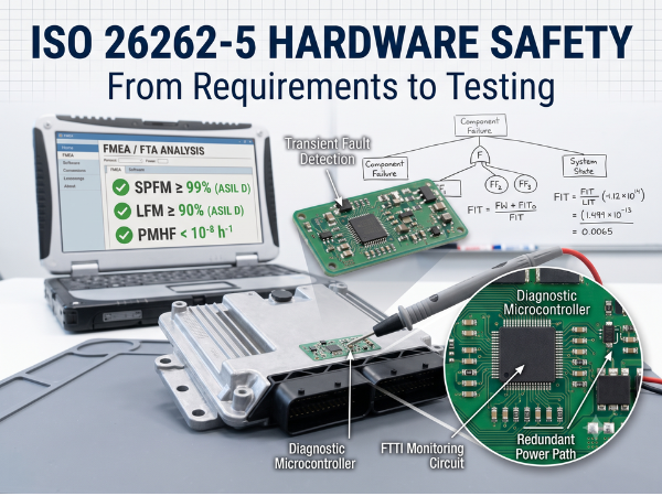
I have spent years working on vehicle hardware. I know how painful functional safety compliance can be. This guide will walk you through ISO 26262-5 (hardware-level development) using clear, practical steps. We will cover everything from requirements to metrics like SPFM, LFM, and PMHF.
Table of Contents
1. The Three Core Hardware Safety Activities
To keep automotive systems safe, we cannot just hope the hardware works. We must design it to handle failures.
ISO 26262-5 outlines three main activities you must perform:
- Build the technical safety concept into the hardware.
- Analyze potential hardware faults and figure out their effects.
- Coordinate closely with the software team.
The Logic Behind Clause 8 and Clause 9
The standard uses two distinct clauses to measure how safe your hardware is:
- Clause 8 (Hardware Architecture Metrics): This clause uses two percentages—Single-Point Fault Metric (SPFM) and Latent Fault Metric (LFM)—to measure how well your hardware design and safety mechanisms handle random physical failures.
- Clause 9 (Random Hardware Failures Evaluation): This clause looks at the overall risk. It uses either a math-heavy probability calculation (PMHF) or a cut-set analysis to check if the risk of violating a safety goal is low enough.
2. Setting Up Your Hardware Safety Requirements (HSR)
Your Hardware Safety Requirements (HSR) must flow directly from your system-level Technical Safety Requirements (TSR). You also need to write a detailed Hardware-Software Interface (HSI) specification to show how physical parts and code interact.
Your HSR must cover five key areas:
1) Internal Failure Control
Your requirements must specify how to handle internal failures within your hardware units. This includes ways to catch temporary glitches (transient faults) using tools like watchdogs and timers.
2) Resistance to External Failures
The hardware must survive failures that happen outside its own board. For example, if an external Electronic Control Unit (ECU) fails, your ECU’s inputs must handle issues like open circuits or power line (KL30) short circuits.
3) Inter-Unit Matching
Ensure your safety requirements match and work well with the safety requirements of neighboring hardware units in the car.
4) Fault Detection and Signaling
Your design needs to catch and report faults quickly. You must write requirements to detect common physical failures, including:
- Open pins
- Short to ground
- Short to power
5) Design Verification Rules
The HSR should not lock you into a specific safety mechanism. Instead, it must define the rules you will use to verify the design later. These rules include:
- Environmental limits: Temperature, vibration, and electromagnetic interference (EMI).
- Operating conditions: Power supply voltage ranges and the expected lifetime usage (mission profiles).
- Component-specific rules: Requirements for specific microchips or power drivers.
3. Hardware Design: From Architecture to Schematics
Hardware design moves from the big-picture architecture down to the actual circuit schematics.
Big-Picture Architecture
Your architecture shows all your hardware units and how they connect.
- ASIL Inheritance: Every hardware unit must meet the safety requirements of the highest Automotive Safety Integrity Level (ASIL) assigned to it.
- Traceability is Crucial: You must be able to trace your requirements from the high-level HSR down to the smallest functional circuit block on your board. This bidirectional traceability is the core rule of both ISO 26262 and ASPICE.
- Keep It Simple: To avoid design mistakes, make your layout modular, keep the blocks reasonably sized, and avoid unnecessary complexity.
- Environmental Stress: You must consider real-world factors like heat, vibration, humidity, dust, and electrical noise (EMI) from other components on the vehicle. These considerations belong in your Design Verification Plan (DVP) tests (EMC, electrical, and life-cycle environmental testing).
Detailed Schematic Design
When you start drawing lines on your schematic, follow these rules:
- Learn from the Past: Follow your company’s safety culture and use lessons learned from past projects (see ISO 26262-2:2018, Clause 5.4.7).
- Prevent Physical Overstress: Design your circuits to survive electrical noise, heat, and moisture.
- Stay Within Limits: Make sure all parts operate within their specified environmental limits.
- Use Robust Methods: Use reliable quality-management (QM) design practices. These include conservative component selection, component derating (running parts below their maximum limits), and Worst-Case Circuit Analysis (WCCA).
4. Hardware Safety Analysis: Classifying Faults
To find where your hardware might fail, you must perform a safety analysis. This analysis is based on ISO 26262-9:2011 Clause 8.
This analysis helps you refine your design early on and verifies your work later. It is mandatory for systems targetting ASIL (B), C, or D.
Your safety analysis must look at three types of faults:
- Safe Faults: Faults that do not directly violate your safety goals.
- Single-Point Faults (SPF) / Residual Faults (RF).
- Multi-Point Faults (MPF) (including perceived, detected, and latent faults).
In most real projects, you can limit your multi-point analysis to dual-point faults (two independent failures happening together). You do not need to analyze every single possible combination of two parts failing. Instead, focus on combinations where one failure affects a core hardware part and the second failure breaks the safety mechanism meant to guard that part.
Single-Point Faults (SPF)
An SPF is a physical failure in a single hardware component that is not caught by any safety mechanism and directly causes the system to violate a safety goal.
To prove you have mitigated SPFs for ASIL (B), C, or D systems, you must show:
- A) Reliable Safety Mechanisms: You have safety mechanisms that can keep the system safe or switch it to a safe state. This must happen within the system’s Fault Tolerant Time Interval (FTTI).
- B) High Diagnostic Coverage: You must calculate how many residual faults your diagnostics can catch.
Key Design Rules for SPFs:
- The FTTI Rule: If your diagnostic test takes too long to run, or if the safety mechanism takes too long to respond, and the total time is longer than your FTTI, the mechanism is not valid.
- Power-Up Checks: If a fault can only be caught at startup, you must run your self-tests immediately when the vehicle powers up, before driving begins.
- Analytical Tools: Use Failure Mode and Effects Analysis (FMEA) or Fault Tree Analysis (FTA) to prove your calculations.
- Evaluation Level: Depending on your components, you can analyze the chip as a whole or look closely at individual pin failure modes.
Latent Faults
A latent fault is a multiple-point failure that is not caught by your safety mechanisms and cannot be noticed by the driver. Over time, these hidden failures build up and can cause sudden system failures when a second part breaks.
To prove you have protected against latent faults, you must show:
- A) Driver Notification: The system can detect the first fault and warn the driver within an acceptable time frame before a second fault occurs.
- B) Measured Coverage: You must evaluate and calculate your diagnostic coverage for these hidden faults.
Key Design Rules for Latent Faults:
- If your diagnostic test interval plus your response time is longer than the time window defined for multi-point fault detection, the fault is considered un-covered (latent).
- Use quantitative FMEA or FTA to build your math model.
Verification: The Relationship Between 3a/3b and 1a/1b
During design verification, standard methods 3a and 3b act as specific checks on environmental and robust design principles. Use them to supplement and strengthen your basic verification methods 1a and 1b.
5. Hardware Architecture Metrics and Failure Rates
To prove your design is safe to external auditors, you must calculate its architectural metrics.
Where to Find Failure Rate (FIT) Data
You cannot make up failure rates. You must get your Failure in Time (FIT) data from one of these three sources:
Source 1: Recognized Industry Standards
This is the most common way to find component failure rates. You can use:
- SN 29500 (Siemens standard, widely used in the automotive industry).
- IEC/TR 62380 or IEC 61709.
- MIL HDBK 217 F Notice 2 or RIAC HDBK 217.
- UTE C80-811.
- NPRD95.
- EN 50129:2003 Annex C or IEC 62061:2005 Annex D.
- RIAC FMD97 or MIL HDBK 338.
Source 2: Field Return Data
You can use real data from vehicles on the road, but your data must have a high confidence level.
Source 3: Structured Expert Judgment
If no data exists, you can use structured evaluations from engineering experts. You must write down the exact reasons and standards used for their judgment.
Metric Targets for ASIL Levels
To pass an audit, your design must meet the following minimum targets:
| Metric | ASIL B | ASIL C | ASIL D |
|---|---|---|---|
| Single-Point Fault Metric (SPFM) | $\ge 90\%$ | $\ge 97\%$ | $\ge 99\%$ |
| Latent Fault Metric (LFM) | $\ge 60\%$ | $\ge 80\%$ | $\ge 90\%$ |
| Random Hardware Failure Probability (PMHF) | $< 10^{-7} \text{ h}^{-1}$ (100 FIT) | $< 10^{-7} \text{ h}^{-1}$ (100 FIT) | $< 10^{-8} \text{ h}^{-1}$ (10 FIT) |
6. Closing the Loop: Hardware Safety Testing
You cannot rely only on paperwork and calculations. You must physically test your hardware to find any remaining design flaws.
To verify your safety mechanisms, write test cases based on these three testing methods:
A. Functional Testing
This test proves your board does what it is supposed to do under normal conditions. You provide normal inputs and check if the outputs match your specifications. If anything looks off, you must analyze why.
B. Fault Injection Testing
This test proves your safety mechanisms actually work when things go wrong. You physically damage or simulate a failure on the board (like shorting a pin to ground) and watch how the system reacts. This is the best way to verify safety reaction times.
C. Electrical Testing
This test verifies your design across its entire operating voltage range. You run the board under high voltage, low voltage, and sudden voltage spikes to ensure it remains stable.
Environmental Stress Testing
You must also test how well the hardware handles external physical stress. This includes running the board during high-vibration tests, temperature cycling tests (from deep freeze to hot conditions), and heavy electromagnetic noise (EMC) testing.
Final Thoughts
Functional safety is an iterative process. You start with requirements, design your circuits, analyze them with FMEAs and calculations, and then verify everything with physical testing. If your tests show weaknesses, you go back, update the design, and test again. By following this cycle, we build vehicles that are truly safe and robust.
FAQs
Q1: What happens if your diagnostic test and safety response take longer than the Fault Tolerant Time Interval (FTTI)?
Short Answer: The safety mechanism is invalid because it cannot protect the system in time.
Details: If a failure occurs and your diagnostics take too long to detect it, the system might crash or behave dangerously before your safety mechanism can kick in. Your total reaction time—from the moment the physical fault occurs to the moment the system reaches a safe state—must always be shorter than the FTTI.
Q2: What is the relationship between the 3a/3b and 1a/1b verification methods in ISO 26262-5?
Short Answer: Methods 3a and 3b are specific, targeted checks that you use to support and strengthen your basic 1a and 1b design checks.
Details: Methods 1a (checking environmental limits) and 1b (using design rules like derating and WCCA) are your fundamental design practices. Methods 3a and 3b act as a second layer of verification. They focus on specific physical failure points and environmental conditions to ensure nothing was missed in the initial design.
Q3: Why is the SN 29500 standard so popular for calculating hardware failure rates?
Short Answer: It is the most trusted and widely accepted failure rate database in the automotive supply chain.
Details: While standards like MIL-HDBK-217F or IEC/TR 62380 are useful, SN 29500 (developed by Siemens) provides highly realistic and updated failure rates for modern silicon chips and passive components. Using it ensures your calculations are consistent with what car manufacturers and tier-1 suppliers expect during functional safety audits.