





Author: Johnny Liu, CEO at Dowway Vehicle
Published: July 2, 2026
Category: Structural Analysis / Finite Element Method (FEM) / Automotive Engineering
Quick Summary
- The Mechanism: Abaqus cuts the bolt shank and pulls the nodes on both sides together to shorten the bolt. It does not simply apply a tensile force.
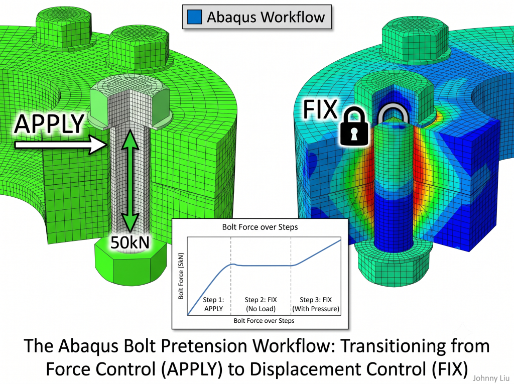
- The Settings: Use *Bolt Load, APPLY to pull the bolt initially. Switch to *Bolt Load, FIX to lock its length for all subsequent load steps.
- The Core Trap: Each new step resets your bolt settings because of op=NEW. You must list every single bolt and set them to FIX in every subsequent step, or your bolts will lose their tension.
- Best Practice: Use a three-step run. Step 1 applies the load, Step 2 locks the bolt with no other forces to let the model settle, and Step 3 adds your working loads.
Table of Contents
The “Preload Reset” Trap in FEA
When I first started simulating bolted joints and high-pressure seals at Dowway Vehicle, I ran into a frustrating issue. I would set up my model, apply the bolt preloads, and run the job. But as soon as the working loads started in the next step, the bolt forces went wild or dropped to zero.
I spent hours checking material parameters, playing with contact stiffness, and remeshing. Finally, I found the issue: I forgot to lock the bolt displacement with the FIX command in the subsequent steps.
This guide covers how bolt pretension works under the hood in Abaqus, outlines a reliable three-step workflow, breaks down the INP keywords, and runs through a real-world flange sealing setup so you can avoid these headaches.
1. How Abaqus Handles Bolt Loads
A common mistake is thinking Abaqus applies bolt preload by just putting equal and opposite forces on the bolt ends. The solver actually does something else.
Abaqus needs you to define a Bolt Cross-Section (a cutting plane) inside the bolt shank. The solver then cuts the shank at this plane and pulls the nodes on both sides together. This shortens the bolt to generate the tension.
[ Bolt Head ]
|
+—–+—–+ <- Bolt Cross-Section (Cutting Plane)
| Node A |
| | (Nodes pull toward each other)
| v |
| ^ |
| | |
| Node B |
+—–+—–+
|
[ Bolt Nut ]
Because of this setup, you have to tell the solver what to do with this shortened length in later steps. If you do not change the settings, Abaqus keeps trying to control the force directly. This makes the bolt behave unnaturally when external loads deform the structure. That is why we must switch from APPLY to FIX.
2. The Two Settings: APPLY vs. FIX
Abaqus uses two main commands to control your bolt loads during a run:
| Command | How it Works | Physical Behavior | When to Use It |
| APPLY | Force Control | Abaqus pulls the bolt until the tension matches your target value. | Pretension Step (The first step where you tighten the bolts). |
| FIX | Displacement Control | Abaqus locks the bolt shortening at its current value. The bolt length stays constant. | Subsequent Steps (When adding working loads, pressure, or heat). |
The Danger of op=NEW
Keep in mind that Abaqus uses op=NEW for loads in new steps. Every time a new step starts, Abaqus wipes out all previous bolt load settings.
If you have a group of bolts, you must list every single bolt in every new step and set them to FIX. If you leave out even one bolt in your pressure step, that bolt loses its pretension. It becomes completely loose, which ruins your contact stress results and causes convergence errors.
3. Step-by-Step Case Study: Flange Joint & Gasket Sealing
Let us look at a standard pipe flange assembly with 4 bolts. We will apply the bolt preloads first, then add internal pressure.
[ 5 MPa Internal Pressure ]
| |
v v
+———————————–+
| Upper Flange |
+—+—+——————-+—+—+
| | [Soft Gasket] | |
| B | ================ | B |
| o | | o |
| l | ================ | l |
| t | [Soft Gasket] | t |
+—+—+——————-+—+—+
| Lower Flange |
+———————————–+
^ ^
(Red Dashed Lines = Bolt Sections)
? Model Specifications
- Flange Material (Q345 Carbon Steel):
- Young’s Modulus:
(
)
- Poisson’s Ratio:
- Bolt Material (40Cr Alloy Steel):
- Size:
, Class 8.8
- Young’s Modulus:
(
)
- Poisson’s Ratio:
- Preload:
per bolt (roughly
of torque)
- Gasket Material (Mild Soft Steel):
- Interaction: Modelled using Soft Contact (exponential pressure-overclosure) to track seal performance.
- Working Load:
- Internal Pressure:
on the inner walls and flange face.
?️ Pre-Processing in Abaqus/CAE
Step 0: Partitioning the Bolt Shank
You cannot apply a bolt load to a raw 3D cylinder. You need a 2D cut plane.
- Open the Part module.
- Click Tools
Partition
Face
Use Datum Plane.
- Place a datum plane through the middle of the bolt shank, parallel to the flange face.
- Cut the shank with this plane. This circular face is your Bolt Cross-Section.
Step 1: Setting up the Bolt Load in the GUI
- Open the Load module
Create Load
select Bolt load.
- For the Region, pick the new circular partition face inside the shank (do not pick the whole 3D bolt).
- Set the Magnitude to 50000 (assuming your unit system is
,
,
).
- Abaqus calculates the Bolt diameter from the face geometry automatically.
- Do this for all 4 bolts. Use clean names like BoltLoad-1, BoltLoad-2, BoltLoad-3, and BoltLoad-4.
? The Three-Step Analysis Plan
Do not try to jam everything into two steps. Adding a quiet intermediate step makes the model much more stable and keeps contact errors away.
+——————————————————————————-+
| Step 1: Pretension Step –> Step 2: Locking Step (No Load) –> Step 3: Working Load Step |
| All bolts: APPLY (50 kN) All bolts: FIX All bolts: FIX |
| Flanges compress. System settles under pure preload 5 MPa pressure applied |
+——————————————————————————-+
- Step 1: Pretension Step (Pretension)
- What happens: All 4 bolts are set to APPLY at
. The flanges squeeze the gasket to establish initial contact.
- Step 2: Locking & Equilibrium Step (Fix_Pretension)
- What happens: All 4 bolts switch to FIX. Do not add any other loads yet. The system settles under pure preload. Abaqus works out the initial gasket squeeze and contact pressures. If you skip this step and apply pressure right away, the solver has to handle contact setup and high working loads at the same time, which often crashes the run.
- Step 3: Working Load Step (WorkLoad_InternalPressure)
- What happens: All 4 bolts stay on FIX. We apply the
internal pressure. The pressure tries to push the flanges apart. Since the bolt lengths are locked, the actual tension in the bolts will change based on how much the flanges stretch.
4. INP Keyword Structure
Here is the correct INP syntax for the three steps. Note how we list every bolt with op=NEW in each step.
Step 1: Apply Bolt Preload
*Step, name=Pretension, nlgeom=YES
*Static
0.1, 1., 1e-05, 0.1
** Define the initial bolt loads using APPLY
*Bolt Load, op=NEW
BoltLoad-1, APPLY, 50000.
BoltLoad-2, APPLY, 50000.
BoltLoad-3, APPLY, 50000.
BoltLoad-4, APPLY, 50000.
*Output, field
*Node Output
U, RF
*Element Output
S, MISES, PEEQ
*End Step
Step 2: Lock the Preload (Letting the Model Settle)
*Step, name=Fix_Pretension, nlgeom=YES
*Static
0.1, 1., 1e-05, 0.1
** Switch all bolt loads to FIX.
** op=NEW clears previous steps and redefines them.
*Bolt Load, op=NEW
BoltLoad-1, FIX
BoltLoad-2, FIX
BoltLoad-3, FIX
BoltLoad-4, FIX
** No external loads are added here to let contact stabilize.
*End Step
Step 3: Apply the 5 MPa Pressure
*Step, name=WorkLoad_InternalPressure, nlgeom=YES
*Static
0.1, 1., 1e-05, 0.1
** All bolts must remain on FIX
*Bolt Load, op=NEW
BoltLoad-1, FIX
BoltLoad-2, FIX
BoltLoad-3, FIX
BoltLoad-4, FIX
** Apply 5 MPa pressure to the inner surfaces and end faces
*Dsload
InnerWall-Surface, P, 5.
FlangeEnd-Surface, P, 5.
*Output, field
*Node Output
U, RF
*Element Output
S, MISES, CPRESS
*End Step
5. Post-Processing: Reading Your Bolt Forces
Once the job runs successfully, you need to check how the bolts are performing. Here are the two best ways to do it:
Method 1: History Output of Bolt Load (BFORCEU1)
To get a clean force curve over time, request history output in your input file:
*Output, history
*Bolt Load Output
BoltLoad-1, BoltLoad-2, BoltLoad-3, BoltLoad-4
- The Variable: Look for BFORCEU1 (force in the bolt axis direction).
- Where to find it: Go to Visualization
XY Data
ODB History Output and plot the force over all three steps.
Method 2: Free Body Cut (FBC)
If you did not set up history output before running:
- Open your model in the Visualization module.
- Click Tools
Free Body Cut
Create.
- Pick your bolt cross-section partition plane.
- Abaqus sums up the forces on the cut plane and shows the total force vector. This is a great way to double-check your BFORCEU1 values.
6. Understanding the Physics: The 3 Sealing Phenomena
Looking at the bolt forces and gasket pressures over the steps reveals three key physical behaviors:
Force & Pressure
^
| /— [Bolt Force (BFORCEU1)]
| /———/
| /———-/ (Lock) \=== [Gasket Contact Pressure (CPRESS)]
| / (Apply) \___
| /
+——-+————–+———+———> Time/Step
Step 1 Step 2 Step 3
(Pretension) (Locking) (Pressure Applied)
1. Bolt Force Rises After Pressurisation
Under 5 MPa pressure, the fluid tries to push the flanges apart. Since the bolt length is locked (FIX), this separation stretches the bolts further. This causes the actual working force of the bolt to rise past the initial 50 kN preload.
- Tip: If your bolt force drops here, check your pressure direction—you might have applied suction instead of pressure.
2. Flange Warping Causes Uneven Contact Pressure (CPRESS)
Plotting the contact pressure across the gasket shows high pressure near the bolt holes and low pressure along the inner and outer edges. This happens because the flanges bend slightly under load.
- Tip: If your contact pressure looks perfectly uniform, your flanges are likely modeled as too rigid, which gives unrealistic sealing results.
3. Checking for Leaks (CPRESS vs. Fluid Pressure)
When pressure is applied in Step 3, the gasket pressure drops. To prevent leaks, make sure:
Where
is the internal pressure (
), and
is the residual contact pressure coefficient (usually
to
depending on the fluid and industry standards). If your minimum contact pressure drops below this limit, the seal will leak.
7. Troubleshooting Checklist: Common Mistakes
If your model is crashing or showing strange results, run through this quick list:
- Bolt Force Drops to Zero in Step 3
- What went wrong: You used op=NEW in Step 3 but did not list your bolts with FIX. The solver assumed the bolts were free.
- How to fix it: Make sure every bolt is declared under *Bolt Load, op=NEW with FIX in Step 3.
- “Bolt load region must be a single face” Error
- What went wrong: You selected the whole 3D bolt body instead of the 2D partition plane.
- How to fix it: Partition the shank and select only the internal circular face.
- Unit Mismatches
- What went wrong: Your forces or stresses are off by massive amounts (e.g., entering 50 instead of 50000 for a model in mm and N).
- How to fix it: Stick to one unit system. For mm-N-MPa:
- Length:
- Force:
- Stress:
- Preload: 50000 (for
)
- Internal Pressure: 5 (for
)
- Instant Penetration or Convergence Errors in Step 1
- What went wrong: You applied preloads before contact was fully established.
- How to fix it: Check your contact settings. Use a small initial adjustment or an interference step to stabilize things before the preloads kick in.
8. Quick FAQ
Q1: Can I apply torque directly in Abaqus instead of Bolt Load?
No, torque is highly sensitive to thread friction. The standard way is to convert torque () to tension (
) using:
Where
is torque (
),
is nominal diameter (
), and
is the torque coefficient (usually around
). Apply the resulting force (
) using the Bolt Load feature.
Q2: What happens if I keep the bolt set to APPLY during the working load step?
The bolt will act like a constant weight pulling on the joint. It will stay at exactly 50 kN instead of stretching naturally as the flanges deform. This leads to underestimating bolt stress and overestimating joint separation.
Q3: How do I handle complex, multi-bolt tightening sequences?
Split your pretension step into sequential sub-steps. For example, apply preloads to Bolt 1 and 3 in Step 1a, lock them in Step 1b while applying preloads to Bolt 2 and 4, and then lock all of them in Step 1c. This captures real-world elastic relaxation.
About the Author
Johnny Liu is the CEO at Dowway Vehicle. With over 15 years of experience in automotive powertrain integration and chassis design, Johnny focuses on joint dynamics, structural fatigue, and high-pressure sealing optimization in demanding environments.