News

news

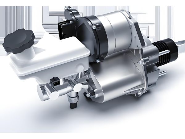
Electronic Hydraulic Brake (EHB) unit with electric motor actuator, brake fluid reservoir, and master cylinder assembly for electric vehicles

Brake-by-Wire (BBW) Deep Dive: How EHB Tech Powers Modern EVs and Autonomous Cars

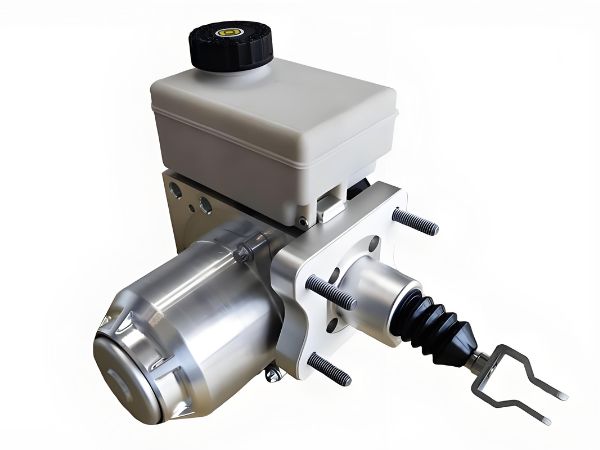
Author: Johnny Liu | CEO at Dowway Vehicle Published: July 2, 2026 Category: Smart Chassis Series #06 Reading Time: ~8 minutes (~1,750 words) Reading Level: Grade 8 (Clear, direct technical language) Quick Take: What is an Electronic Hydraulic Brake (EHB)? An Electronic Hydraulic Brake (EHB) is a brake-by-wire system that replaces old engine-driven vacuum boosters […]

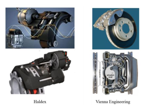
3D rendered diagrams and prototypes of Electro-Mechanical Brake (EMB) actuators from Haldex and Vienna Engineering showing motor drives, calipers, and internal actuation mechanisms.

Electro-Mechanical Brake (EMB) Systems: Structure, Control, and Real-World Uses

Author: Johnny Liu, CEO at Dowway Vehicle Source Reference: Based on research by Prof. Lu Xiong’s team at Tongji University (Sustainability, DOI: 10.3390/su15054514). Date: June 2, 2026 | Updated: August 3, 2026 Reading Level: 8th Grade (Clear explanations without dropping tech details) What Is an Electro-Mechanical Brake (EMB)? Modern electric vehicles and self-driving cars need

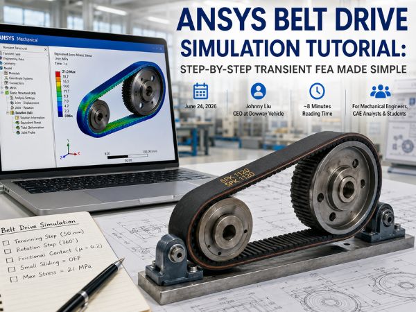
ANSYS belt drive transient structural simulation displayed on a laptop beside a physical belt-and-pulley test assembly in a bright engineering workshop.

ANSYS Belt Drive Simulation Tutorial: Step-by-Step Transient FEA Made Simple

Author: Johnny Liu | CEO at Dowway Vehicle Published: June 24, 2026 Reading Time: Approximately 8 Minutes (1,820 Words) Target Audience: Mechanical Engineers, CAE Analysts, Automotive Engineers, and Engineering Students Category: Automotive Engineering and FEA Simulation Guidance Author Experience About the Author Johnny Liu is the CEO at Dowway Vehicle, a manufacturer of commercial and

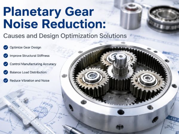
Planetary gearbox with precision gears illustrating noise reduction design, vibration control, and engineering optimization solutions.

Planetary Gear Noise Reduction: Causes and Design Optimization Solutions

Author: Johnny Liu, CEO at Dowway VehicleEngineering Focus: Vehicle drivetrain systems, planetary gearbox design, noise and vibration controlLast Updated: July 2026 Quick Answer: What Causes Planetary Gear Noise and How Can It Be Reduced? Planetary gear noise usually comes from gear meshing errors, manufacturing variation, structural vibration, assembly problems, lubrication issues, and unstable operating conditions.

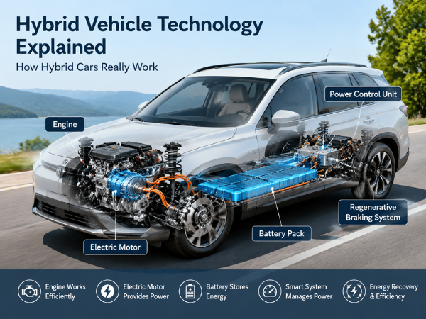
Hybrid vehicle technology explained with a transparent car design showing the engine, electric motor, battery pack, power control unit, and regenerative braking system.

Hybrid Vehicle Technology Explained: How Hybrid Cars Really Work

Published: July 27, 2026Last Updated: July 27, 2026 Written by Johnny LiuCEO at Dowway Vehicle About the Author Johnny Liu is the CEO at Dowway Vehicle, focusing on vehicle technology trends, automotive innovation, and the development of electrified mobility solutions. Through studying global vehicle technologies and market changes, Johnny focuses on one key question: How

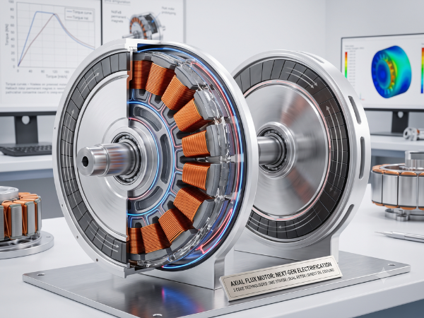
A detailed, brightly lit cutaway visualization of a next-generation axial flux electric motor prototype mounted on a test stand in a modern engineering laboratory. The image reveals the internal "pancake" structure, showcasing copper coil windings, rotor disks with permanent magnets, and blue/red lines illustrating internal cooling paths. In the background, computer monitors display technical graphs and simulation data.

Axial Flux Motors: Fundamentals and the 3 Core Technologies Shaping Next-Gen Electrification

1. Introduction: The Shift in Electric Motor Design For over a century, the electric vehicle (EV) industry and industrial automation relied almost exclusively on Radial Flux Motors (RFM). In a radial flux design, magnetic flux travels radially outward across a cylindrical air gap between concentric rotor and stator elements. While reliable and mature, conventional radial

Alt Text: A detailed infographic comparing the legacy 3-in-1 EV drive system with the StarDrive (Xingqu Tech) Thunder 16-in-1 Intelligent Electric Drive System. The image features a large technical cutaway view of the integrated 16-in-1 unit, highlighting internal components like the motor, reducer, and inverter within a shared shell. Annotations detail its specifications, including 12 hardware and control functions, 4 domain software capabilities, a weight of 75kg, and an efficiency of 93.8%. Diagrams illustrate reclaimed space and an estimated BOM cost reduction of approximately 800 RMB.

From 3-in-1 to 16-in-1: How E-Drive Integration Rewrites EV Costs, Space, and Supply Chains

By: Johnny Liu | CEO at Dowway Vehicle Published: July 22, 2026 Category: Automotive Powertrain Architecture & Supply Chain Strategy Reading Time: 14 min read What is a 16-in-1 E-Drive System? A 16-in-1 electric drive (e-drive) system combines 12 hardware and control functions with 4 domain software capabilities into one physical assembly. First built commercially

Side-by-side comparison illustrating a traditional mechanical handbrake lever with its cable-driven rear suspension system (left) versus a modern electronic parking brake button, ECU, and motorized caliper (right) with directional arrows showing the digital control flow.

Mechanical Handbrake (PB) vs. Electronic Parking Brake (EPB): Technical Mechanics, Differences, and Future Trends

Author Biography Johnny Liu is the Chief Executive Officer at Dowway Vehicle, a global provider of automotive chassis solutions, braking technologies, and aftermarket components. With over 20 years of hands-on mechanical engineering and executive leadership in automotive manufacturing, Johnny specializes in modern vehicle safety architectures, drive-by-wire system integration, and braking component design. Executive Summary What

A close-up photograph capturing an engineer's hand wearing a white glove, gently probing a central processor unit (CPU) on an open automotive engine control unit (ECU). The ECU is connected by a cable to a multi-channel signal generator with a display showing waveform, and then to a laptop. The laptop screen displays 'Fault Injection Management' software, showcasing charts like 'Fault Detection Rate' (green bars) and 'Fault Injector Status', indicating an ongoing fault injection reliability test. The background is a well-lit, professional electronics development lab with an oscilloscope and other equipment blurred.

Testing IC and Software Reliability: A Practical Guide to Fault Injection

Author: Johnny Liu, CEO at Dowway Vehicle Published: July 21, 2026 Category: Embedded Systems, Automotive Safety, Hardware Engineering, Compliance As the CEO of Dowway Vehicle, where we build safety-critical systems for cars, I know that reliability is not just a checkbox. In our line of work, an undetected chip failure or a brief software error

Need a Quote or Have Questions?

Please fill out the form below, our engineers will contact you within 24 hours.