News

news

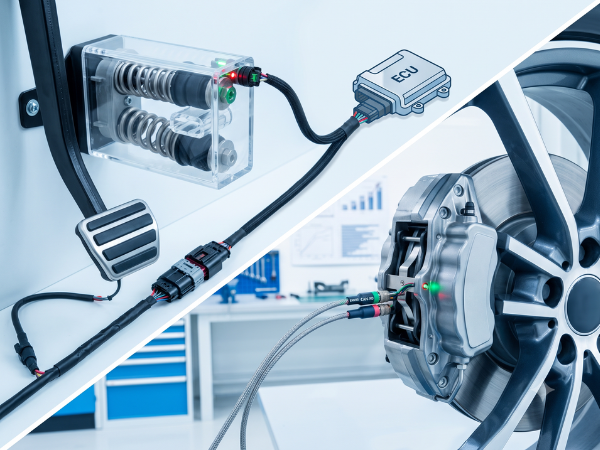
A technical split-screen view illustrating brake-by-wire technology. The left side shows a brake pedal unit with a visible internal simulator and springs, representing human input. The right side features a vehicle wheel and disk brake caliper with electronic cables, symbolizing electronic actuation and control.

The Brake-by-Wire Truth: Fake Pedal Feel, EHB vs. EMB, and Why F1 Isn’t What You Think

Author: Johnny Liu Title: Chief Executive Officer at Dowway Vehicle Published: July 15, 2026 Reading Time: 15 mins Category: Automotive Engineering, Drive-by-Wire Technology, Chassis Dynamics Author’s Note As the CEO of Dowway Vehicle and a chassis engineer, I have spent decades analyzing how cars slow down. In our industry, brake systems are sacred. Yet, as […]
Purpose: Describes the image for users who cannot see it (e.g., those using screen readers) and for search engines. It should be concise and accurately reflect the visual content. Template: [A concise and accurate description of the image content, focusing on the key subject and action. (e.g., 'A medium shot of a brown tabby cat sitting on a windowsill, looking out at a garden.')]

Deciphering Brake-by-Wire Technology: From Friction Brakes to EHB & EMB

About the Author Johnny Liu is the Chief Executive Officer at Dowway Vehicle, a pioneering automotive technology firm specializing in next-generation intelligent chassis systems and drive-by-wire solutions. With over two decades of automotive powertrain and chassis development experience, Johnny leads teams building software-defined electric vehicle (SDV) systems. Executive Summary The automotive industry is shifting from

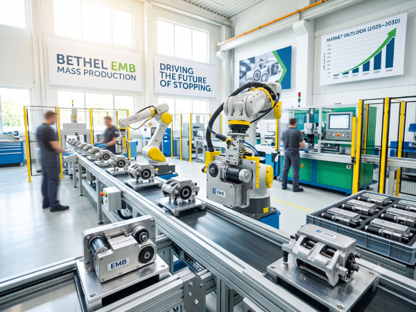
A wide-angle photograph taken inside a modern, bright factory. An automated production line is filled with robotic arms assembling components. Two large banners hang in the background. The left banner reads "BETHEL EMB MASS PRODUCTION". The right banner reads "DRIVING THE FUTURE OF STOPPING". In the foreground, numerous small Electro-Mechanical Brake (EMB) units are visible on a conveyor belt and in containers.

The Future of Stopping: EMB Technology and Market Outlook (2025–2030)

Author: Johnny Liu, CEO at Dowway Vehicle Published: June 15, 2026 Quick Summary of Key Facts 1. Why Is the Traditional Vacuum Booster System Going Away? For decades, the vacuum booster was the standard way to stop a gasoline-powered car. To understand why it is disappearing, we have to look at how it actually works.

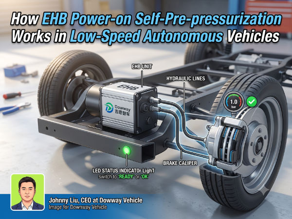
A 3D technical illustration of a drive-by-wire chassis for a low-speed autonomous vehicle, highlighting an Electronic Hydraulic Braking (EHB) unit with the Dowway Vehicle logo, hydraulic lines, a brake caliper, a digital gauge showing 1.0 bar, and an avatar photo of CEO Johnny Liu in the bottom left corner.

How EHB Power-on Self-Pre-pressurization Works in Low-Speed Autonomous Vehicles

Author’s Note “At Dowway Vehicle, we build L4 low-speed autonomous delivery, sanitation, and logistics chassis for real-world deployments. One critical safety item in drive-by-wire vehicles is verifying that the hydraulic braking system is fully functional before the wheels even turn. This technical guide explains how we use EHB Power-on Self-Pre-pressurization to handle safety diagnostics directly

A blue modern sedan making a sharp turn on a city street curve, demonstrating Ackermann steering geometry where the inner front wheel turns at a sharper angle than the outer wheel.

Why Your Front Wheels Don’t Turn at the Same Angle: The Secrets of Ackermann Geometry

Quick Summary What is Ackermann Steering Geometry? It is a smart setup of mechanical links in your car’s steering. It makes the inside front wheel turn at a sharper angle than the outside wheel (usually a$2^\circ$to$5^\circ$difference) when you go around a corner. This ensures both front tires track smoothly around a single, shared turning center,

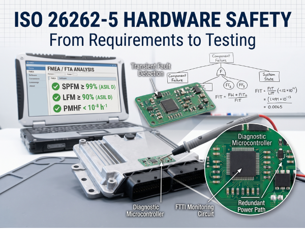
An informational graphic about ISO 26262-5 Hardware Safety, featuring an automotive ECU on a workbench being tested with a probe. A rugged laptop displays FMEA/FTA analysis metrics for ASIL D, including SPFM, LFM, and PMHF. Diagnostic microcontroller and FTTI monitoring circuit diagrams with FIT formulas are overlaid on the image.

ISO 26262-5 Hardware Development Guide: Requirements, Metrics, and Testing

Modern cars are packed with complex electronics. As we build smarter vehicles, the circuit boards and silicon inside must be extremely reliable. I have spent years working on vehicle hardware. I know how painful functional safety compliance can be. This guide will walk you through ISO 26262-5 (hardware-level development) using clear, practical steps. We will

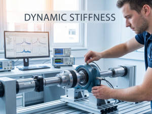
A mechanical engineer adjusting a rotating shaft test rig in a brightly lit laboratory, with vibration analysis curves and frequency charts visible on a computer screen in the background. The text "DYNAMIC STIFFNESS" is overlaid cleanly at the top.

Understanding Dynamic Stiffness in Rotordynamics and Vibration Analysis

About the Author Johnny Liu leads Dowway Vehicle as CEO. With over twenty years in car structural dynamics, chassis setup, and noise, vibration, and harshness (NVH) testing, Johnny focuses on putting fresh rotordynamics and vibration control ideas into practical use for electric drivetrains and vehicle suspension systems. In basic mechanics, stiffness is simple: it is

Need a Quote or Have Questions?

Please fill out the form below, our engineers will contact you within 24 hours.