





Written by Johnny Liu, CEO at Dowway Vehicle
Published Date: August 24, 2026
Last Updated: August 24, 2026
Table of Contents
Quick Answer
Vehicle underbody reliability development evaluates whether the lower vehicle structure can handle real driving loads throughout its service life. In the TOLY 889 project, Dowway Vehicle combined road load testing, virtual road iteration, multi-body dynamics simulation, load decomposition, and CAE fatigue analysis to find structural risks before durability testing.
Project Overview
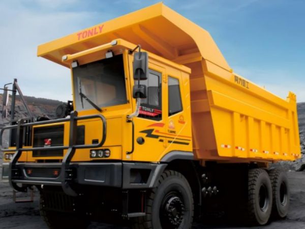
The TOLY 889 Vehicle Underbody Reliability Development Project was completed by Dowway Vehicle in 2020 for a new vehicle platform development program.
The project focused on improving underbody durability through a complete engineering process:
Road Load Testing → Data Processing → Virtual Iteration → Load Decomposition → CAE Strength and Fatigue Analysis → Structural Optimization
The main purpose was to help the customer identify possible fatigue problems earlier, reduce late-stage design changes, and improve vehicle reliability.
| Project Information | Details |
|---|---|
| Project Name | TOLY 889 Vehicle Underbody Platform Reliability Development |
| Company | Dowway Vehicle |
| Year | 2020 |
| Engineering Area | Vehicle chassis durability and reliability |
| Main Work | Road load acquisition, virtual iteration, load analysis, CAE fatigue evaluation |
| Vehicle System | Underbody platform structure |
About the Author
Johnny Liu is the CEO at Dowway Vehicle.
He leads Dowway Vehicle’s engineering programs in automotive reliability development, chassis durability, vehicle testing, and CAE simulation.
Dowway Vehicle works with automotive customers on engineering projects that connect physical vehicle data with digital simulation methods. The company’s development approach uses measured road loads, vehicle dynamics models, and structural analysis to support better design decisions.
What Was the Background of the TOLY 889 Reliability Development Project?
The TOLY 889 was a new vehicle platform where the underbody structure carried major loads from the chassis, suspension system, and powertrain.
The underbody platform is one of the most important structures in vehicle durability development because it transfers forces from road inputs into the vehicle body.
A weak connection point, weld area, or mounting location may create fatigue problems after repeated loading.
Traditional durability development often depends on many rounds of physical vehicle testing. While road testing remains necessary, this method has several challenges:
- High prototype vehicle cost
- Long testing cycles
- Late discovery of fatigue problems
- Additional design changes after testing
Dowway Vehicle developed a test-and-simulation process for TOLY 889 to move reliability evaluation earlier in the vehicle development stage.
The project covered the complete reliability chain from real vehicle measurement to fatigue prediction.
What Were the Goals of the TOLY 889 Underbody Reliability Project?
The project had five main goals.
1. Collect Real Vehicle Road Load Data
Dowway collected full-condition road load information from the TOLY 889 prototype vehicle.
The target was to create reliable load data that could support later simulation work.
The collected information included:
- Wheel center six-component forces
- Acceleration signals
- Structural strain measurements
- Time-history load data
2. Build a Reliable Virtual Simulation Process
The measured road loads needed to be converted into simulation inputs.
Dowway developed a virtual road iteration process to make the multi-body dynamics model reproduce real vehicle behavior.
3. Complete Load Decomposition
The team converted vehicle-level loads into component-level loads.
The output included:
- Suspension hard-point loads
- Subframe mounting loads
- Longitudinal beam connection loads
- Powertrain mounting loads
4. Evaluate Underbody Strength and Fatigue
Dowway performed:
- Static strength analysis
- Fatigue life prediction
- Damage evaluation
- Structural risk identification
5. Support Engineering Optimization
The final results helped the customer improve underbody design before later durability validation.
What Was Included in Dowway’s Project Scope?
Dowway’s responsibility covered the underbody reliability development process.
The work included:
Road Load Acquisition
- Test plan development
- Sensor selection
- Sensor installation
- Road condition planning
- Data collection
- Signal processing
Vehicle Dynamics Simulation
- Multi-body dynamics model development
- Suspension parameter calibration
- Virtual road iteration
- Simulation correlation
Load Analysis
- Interface load calculation
- Hard-point load extraction
- Time-history load generation
CAE Reliability Analysis
- Finite element modeling
- Static strength evaluation
- Fatigue damage calculation
- Structural improvement suggestions
The project did not include:
- Vehicle crash development
- NVH development
- Upper body structure development
- Physical durability road testing execution
How Did Dowway Develop the Vehicle Reliability Workflow?
Dowway used a closed-loop engineering workflow:
Real Vehicle Measurement
↓
Road Load Data Processing
↓
Virtual Road Iteration
↓
Multi-body Dynamics Load Decomposition
↓
Underbody CAE Analysis
↓
Design Optimization
This process connected physical testing and digital engineering.
The measured vehicle behavior provided accurate inputs, while simulation helped predict structural performance before additional vehicle testing.
How Was Road Load Data Acquisition Performed?
Road load acquisition was the foundation of the TOLY 889 reliability development process.
Before testing, Dowway created a detailed measurement plan covering:
- Vehicle loading condition
- Sensor selection
- Sensor installation location
- Test route planning
- Sampling settings
The test vehicle followed customer durability requirements with rated full-load conditions.
Sensor Setup
Dowway installed several measurement systems on the vehicle.
Wheel Center Six-Component Force Sensors
The wheel center sensors captured:
- Three-direction forces
- Three-direction moments
These measurements represented the real loads transferred from the road into the vehicle.
Acceleration Sensors
Acceleration sensors were installed at important underbody locations to measure structural response.
Strain Measurement Channels
Strain sensors were used to monitor deformation behavior at selected areas.
What Road Conditions Were Included in Testing?
The road test covered different severe conditions that could create underbody fatigue damage.
The test conditions included:
- Belgian road
- Fish-scale road
- Washboard road
- Twist road
- Impact road
- Speed bump impact conditions
These conditions helped capture different types of chassis loading during vehicle operation.
How Was the Road Load Data Processed?
After testing, Dowway processed the raw measurement data before simulation use.
The processing steps included:
- Removing abnormal data sections
- Eliminating signal drift
- Filtering noise
- Removing overload spikes
- Checking channel validity
- Selecting effective load cycles
The final output was a validated road load database for reliability analysis.
How Was Virtual Road Load Iteration Used in the TOLY 889 Project?
After completing road load data acquisition, Dowway needed to convert real vehicle measurements into reliable simulation inputs.
The measured wheel center six-component forces could not be directly applied to the vehicle simulation model. Direct use of raw measurement data could cause model imbalance, inaccurate vehicle response, and unreliable fatigue prediction.
Dowway used virtual road load iteration to solve this problem.
The purpose was to find equivalent virtual road excitation that could make the digital vehicle reproduce the behavior of the physical vehicle.
This step created the connection between:
Real Road Conditions → Digital Vehicle Model → Reliable Structural Load Prediction
Only after the model correlation reached an acceptable level could the team continue with load decomposition and CAE fatigue analysis.
How Did Dowway Build and Validate the Multi-body Dynamics Model?
Dowway developed a TOLY 889 multi-body dynamics model to represent the real vehicle behavior.
The model included important chassis components and parameters:
- Suspension systems
- Bushings
- Springs
- Dampers
- Chassis connection characteristics
The engineering team calibrated the model based on measured vehicle responses.
Vehicle Parameter Calibration
Dowway adjusted key vehicle parameters, including:
Bushings
Bushing stiffness and nonlinear behavior affect how road forces transfer through suspension connections.
Springs
Spring characteristics influence vehicle movement and load transfer.
Dampers
Damper response affects vibration control and impact load transmission.
The team performed repeated calibration until the simulation response matched the physical vehicle behavior.
How Was Simulation Accuracy Evaluated?
Dowway compared simulation results with real vehicle test data using several engineering indicators.
The evaluation included:
RMS Comparison
The Root Mean Square (RMS) value was used to compare overall response levels between simulation and physical testing.
Pseudo Damage Comparison
Pseudo damage was used as an important fatigue-related comparison method.
Instead of only checking whether the waveform looked similar, Dowway evaluated whether the simulation produced similar fatigue damage characteristics.
This made the fatigue prediction more meaningful.
Time History Response Comparison
The team compared:
- Signal trends
- Load changes
- Peak responses
- Response timing
The model was accepted only after achieving reasonable correlation with the measured vehicle behavior.
What Were the Outputs of Virtual Road Iteration?
After completing model validation, Dowway generated:
- Calibrated multi-body dynamics model
- Virtual road excitation files
- Simulation-ready vehicle load inputs
These outputs created reusable engineering assets for:
- Future durability simulation
- Test bench simulation
- Related vehicle platform development
How Did Dowway Perform Multi-body Dynamics Load Decomposition?
After validating the vehicle dynamics model, Dowway performed load decomposition to understand how road loads transferred into the underbody structure.
The process followed the actual vehicle load path:
Road Surface → Tire → Wheel Center → Suspension System → Mounting Points → Underbody Structure
The purpose was to convert vehicle-level road loads into component-level engineering loads.
What Underbody Locations Were Evaluated?
Dowway extracted time-history loads from key structural interfaces.
The analysis included:
Subframe Mounting Points
These areas transfer suspension loads into the vehicle body.
Suspension Hard Points
These locations experience repeated forces during durability operation.
Longitudinal Beam Connection Areas
These structural areas receive continuous road-induced loads.
Powertrain Mounting Points
These locations experience combined loads from the powertrain and road conditions.
What Load Data Was Generated?
The load decomposition process produced:
- Three-direction forces
- Three-direction moments
- Time-history load spectra
These loads became the direct input for underbody finite element analysis.
How Did Load Analysis Help Identify Fatigue Sources?
Dowway also analyzed damage contribution from different load conditions.
The engineering team evaluated:
- Which road conditions created higher fatigue damage
- Which load channels contributed more damage
- Which structural locations needed attention
This allowed the customer to understand the relationship between road conditions, load transfer, and structural fatigue risk.
How Was Underbody Strength and Fatigue CAE Analysis Performed?
After obtaining interface load spectra, Dowway imported the loads into the underbody finite element model.
The CAE work included two major evaluations:
- Static strength analysis
- Fatigue life analysis
Static Strength Analysis for Underbody Structures
Static strength analysis focused on extreme loading conditions.
Dowway selected severe impact load cases to evaluate structural performance.
The analysis checked:
- Stress distribution
- Material yield risk
- High stress concentration areas
The goal was to identify locations where the structure might not meet strength requirements.
Typical attention areas included:
- Suspension mounting areas
- Structural joints
- Load transfer connections
The results helped engineers improve weak areas before physical durability testing.
Fatigue Life Prediction Using CAE Simulation
Fatigue analysis evaluated long-term structural durability under repeated loading.
Dowway used:
- Material S-N curves
- Rainflow counting method
- Cumulative fatigue damage calculation
The calculation process converted repeated load cycles into fatigue damage values.
The output included:
- Fatigue damage distribution
- Life prediction results
- High-risk area identification
How Did Dowway Evaluate Weld Fatigue Risks?
Underbody structures often contain many welded connections.
These areas require special attention because fatigue cracks commonly start around weld locations.
Dowway focused on:
Weld Points
Detailed weld modeling was used to improve fatigue prediction accuracy.
Weld Seams
Appropriate welding fatigue parameters were applied during analysis.
Stress Concentration Areas
Areas with concentrated stress were reviewed for possible durability concerns.
The approach matched common vehicle durability failure patterns and helped engineers focus on realistic risk areas.
What Structural Optimization Suggestions Were Provided?
After identifying high-damage locations, Dowway provided engineering recommendations.
The optimization suggestions included:
Local Reinforcement
Additional support structures could be added in weak areas.
Thickness Optimization
Material thickness could be adjusted to improve strength and fatigue performance.
Fillet Transition Improvement
Corner transitions could be modified to reduce stress concentration.
Welding Layout Optimization
Weld locations and patterns could be adjusted to improve fatigue resistance.
Dowway compared different improvement options and evaluated their effect on fatigue damage reduction.
The final recommendations supported the customer’s underbody design review process.
What Were the Main Technical Challenges and Solutions?
The TOLY 889 project included several engineering challenges. Dowway developed practical solutions based on testing and simulation experience.
| Challenge | Solution |
|---|---|
| Road load measurement interference and signal distortion | Improved sensor installation, vibration protection, repeated testing, and signal diagnosis |
| Difference between simulation response and vehicle test response | Improved chassis parameter calibration and performed staged virtual iteration |
| Complex fatigue prediction in welded underbody structures | Used detailed weld modeling and suitable fatigue parameters |
Challenge 1: Road Load Measurement Signal Problems
During road testing, some measurement channels experienced:
- Signal interference
- Noise
- Signal distortion
Poor-quality data could affect later simulation results.
Dowway improved measurement reliability through:
- Better sensor installation methods
- Additional vibration protection
- Multiple sampling rounds
- Signal diagnosis tools
- Faulty channel identification
- Additional validation measurements
These actions helped maintain reliable core load channels.
Challenge 2: Virtual Iteration Correlation Problems
The first simulation results showed differences compared with physical vehicle testing.
Dowway improved correlation through:
- Detailed bushing parameter calibration
- Damper characteristic adjustment
- Nonlinear chassis parameter refinement
The iteration process was performed step by step:
- Lower vibration road conditions
- Higher load conditions
- Severe impact road conditions
The team used pseudo damage as a key evaluation indicator instead of only comparing time-domain signals.
This improved the reliability of fatigue prediction.
Challenge 3: Fatigue Prediction of Complex Welded Structures
Underbody structures contain complex welded areas.
Predicting weld fatigue behavior requires detailed modeling methods.
Dowway addressed this challenge through:
- Detailed weld modeling
- Welding fatigue material parameters
- Focused weld damage evaluation
This approach helped match simulation results with real vehicle durability behavior.
What Were the Final Deliverables of the TOLY 889 Project?
Dowway delivered a complete reliability development package.
The main outputs included:
1. TOLY 889 Underbody Reliability Development Report
The report included:
- Test results
- Simulation results
- Structural risk evaluation
- Engineering recommendations
2. Road Load Data Package
Including:
- Original road load measurement data
- Processed valid road spectrum files
3. Simulation Model Package
Including:
- Validated multi-body dynamics model
- Virtual road excitation files
4. Underbody Interface Load Spectrum
Including:
- Hard-point load data
- Time-history forces
- Moment load information
5. CAE Simulation Results
Including:
- Finite element models
- Static strength results
- Fatigue damage cloud maps
6. Structural Risk Assessment Report
Including:
- High-risk locations
- Fatigue concerns
- Optimization recommendations
7. Technical Review Materials
Dowway prepared technical presentation materials to support customer internal engineering reviews.
What Value Did the TOLY 889 Reliability Project Deliver?
The project created value in three important areas.
Earlier Risk Detection
Dowway identified possible fatigue risks before full durability road testing.
The analysis helped locate:
- Stress concentration areas
- Weak structural locations
- Fatigue-sensitive regions
This allowed engineers to improve the design earlier.
Improved Development Efficiency
The combination of physical testing and simulation reduced dependence on repeated prototype changes.
The project helped reduce:
- Testing cycles
- Prototype modification work
- Development cost
Reusable Engineering Data
The project created long-term engineering resources:
- Road load database
- Underbody load spectrum
- Simulation models
- Reliability development workflow
These assets can support future:
- Passenger vehicle platforms
- Commercial vehicles
- Special-purpose vehicles
How Can This Reliability Method Support Future Vehicle Programs?
The TOLY 889 project helped Dowway establish a repeatable vehicle reliability development process:
Road Load Acquisition → Virtual Iteration → Load Decomposition → CAE Fatigue Evaluation
This method can support future automotive programs by helping engineers evaluate durability risks earlier and make better structural decisions.
The same approach can be applied to:
- New vehicle platforms
- Platform derivative models
- Commercial vehicle chassis
- Special vehicle development
Frequently Asked Questions (FAQ)
What is vehicle underbody reliability development?
Short answer:
Vehicle underbody reliability development checks whether the lower vehicle structure can handle repeated road loads during its service life. Engineers use testing, simulation, and fatigue analysis to find weak areas before vehicle production.
The process normally combines road load measurement, vehicle dynamics simulation, structural analysis, and design improvement. In the TOLY 889 project, Dowway used this method to evaluate underbody durability before later vehicle validation.
Why is road load data important in automotive durability development?
Short answer:
Road load data records the real forces and moments a vehicle experiences during driving. It provides accurate input for simulation models and fatigue analysis.
Without reliable road load data, engineers cannot accurately predict structural fatigue performance. Dowway collected wheel center forces, acceleration signals, and strain data to create a validated load database for TOLY 889.
How does multi-body dynamics simulation help vehicle development?
Short answer:
Multi-body dynamics simulation shows how road forces transfer through vehicle systems and reach structural mounting points.
In the TOLY 889 project, Dowway used a calibrated dynamics model to convert vehicle-level road inputs into component-level loads for CAE analysis.
Why is CAE fatigue analysis needed for underbody structures?
Short answer:
CAE fatigue analysis predicts whether vehicle structures may develop damage after repeated loading cycles.
By using S-N curves, rainflow counting, and damage calculations, engineers can identify fatigue risks before physical failures occur.
Why combine vehicle testing and simulation?
Short answer:
Testing provides real vehicle behavior, while simulation helps predict future performance.
The combination allows engineers to understand actual loads, analyze structural response, and improve designs before large-scale testing and production.
Final Engineering Note
The TOLY 889 Vehicle Underbody Reliability Development Project shows how Dowway Vehicle uses real vehicle data and simulation technology together to support modern vehicle durability development.
By connecting road load testing, virtual iteration, multi-body dynamics, load decomposition, and CAE fatigue analysis, Dowway helped create a reliable engineering process for identifying structural risks earlier and supporting better vehicle design decisions.
Dowway Vehicle continues to support automotive companies with reliability engineering solutions based on measured data, simulation accuracy, and practical vehicle development experience.