





- Author: Johnny Liu (CEO at Dowway Vehicle | Automotive Systems Specialist)
- Published: July 1, 2026
- Category: Embedded Systems / Automotive Engineering / MCU Programming
? TL;DR
This guide provides a step-by-step tutorial on implementing STM32 CAN (Controller Area Network) communication using the STM32 HAL Library (bxCAN). Written by an automotive electronics expert, it covers physical hardware setup, precise baud rate calculation with Time Quanta (TQ), zero-filter “Accept-All” configurations, interrupt-driven message reception, and real-world industrial troubleshooting guidelines.
Table of Contents
1. Introduction
In automotive engineering and industrial automation, the Controller Area Network (CAN) remains the standard for robust, noise-tolerant communication. In our previous theoretical articles, we explored the CAN Physical Layer, Frame Format, Arbitration, and Error Handling mechanisms.
Now, it is time to bridge the gap between theory and execution. How do we write practical, production-ready code to send and receive a single CAN frame on an STM32 microcontroller?
This article focuses on the classic bxCAN peripheral using the STM32 HAL Library (perfect for STM32F1, F4, and similar series). Whether you are designing an Electric Vehicle (EV) control board or a factory automation sensor node, this step-by-step coding framework will provide you with a reliable, scalable foundation.
2. Essential Hardware for STM32 CAN Communication (Why Software Isn’t Enough)
Unlike UART or SPI, where you can simply connect the RX/TX pins of two MCUs together for bench testing, CAN communication requires external physical transceiver hardware. Connecting MCU CAN_TX and CAN_RX pins directly to each other without a transceiver will fail and could damage your GPIO pins.
Key Components of a CAN Node
A functioning CAN node consists of five core elements:
- Internal CAN Controller: Integrated inside the STM32 MCU.
- External CAN Transceiver: Translates the MCU’s digital logic levels ($3.3\text{ V}$) into the physical bus’s differential signals ($\text{CAN\_H}$ and $\text{CAN\_L}$). Common chips include TJA1050, TJA1051, SN65HVD230, or MCP2551.
- Physical Bus Lines: Twisted-pair wires designated as $\text{CAN\_H}$ and $\text{CAN\_L}$ to suppress electromagnetic interference (EMI).
- $120\Omega$ Termination Resistors: Must be placed at both physical ends of the bus to prevent signal reflection.
- Protection Circuits (Recommended for Production): Transient Voltage Suppressors (TVS diodes) and optoelectronic isolation to protect against high-voltage surges.
The Hardware Wiring Reference
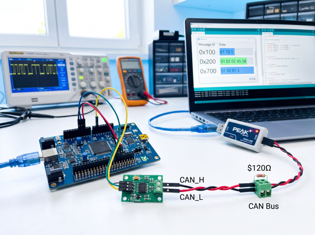
Ensure your prototype or custom board is wired exactly as shown below:
| STM32 MCU Pin | Transceiver Side | Transceiver Bus Side | Physical CAN Bus Line |
STM32 CAN_TX | $\rightarrow$ TXD | CANH | $\rightarrow$ CAN_H (with $120\Omega$ parallel termination) |
STM32 CAN_RX | $\leftarrow$ RXD | CANL | $\rightarrow$ CAN_L (with $120\Omega$ parallel termination) |
3. High-Level Overview: The 8 Steps to CAN Initialization
To establish stable communication on an STM32, the firmware must execute these 8 steps in order:
[1. Init CAN Parameters] ──> [2. Config Baud Rate] ──> [3. Config Working Mode]
                                                                  │
[6. Enable RX Interrupt] <── [5. Start CAN] <── [4. Config Hardware Filters]
         │
[7. Transmit CAN Frame] ──> [8. ISR / Callback Rx Handling]
- Initialize CAN peripheral parameters (allocate memory for the handle, map pin multiplexing).
- Configure the Baud Rate (set prescalers and phase segments).
- Configure the Working Mode (Normal mode for production, Loopback for dry runs).
- Configure Hardware Filters (configure acceptance filters to filter out unwanted IDs at the hardware level).
- Start the CAN Peripheral (transition the CAN hardware state from initialization to active).
- Enable RX Interrupts (instruct the NVIC to listen to incoming CAN messages).
- Transmit CAN Frames (load messages into TX mailboxes).
- Receive CAN Frames in the ISR (handle message parsing inside the designated FIFO interrupt callback).
⚠️ Common Engineering Pitfalls: Most developer headaches originate from wrong baud rate timing configurations, unconfigured (and therefore blocking) filters, forgetting to call
HAL_CAN_Start(), or attempting to transmit without another active node on the bus to generate an Acknowledge (ACK) signal.
4. Understanding STM32 CAN Baud Rate & Time Quanta (TQ)
Configuring the CAN baud rate incorrectly will render your node completely silent or trigger continuous error frames on the bus.
The Mathematical Formula
The CAN baud rate is calculated using the peripheral’s clock and the division of a single bit time into small units called Time Quanta (TQ):$$\text{CAN Baud Rate} = \frac{\text{CAN Clock}}{\text{Prescaler} \times \text{Total Time Quanta per Bit}}$$
The total Time Quanta per bit is defined by the synchronization segment and two phase segments:$$\text{Total Time Quanta per Bit (Total TQ)} = 1 \text{ (Sync Seg)} + \text{BS1} + \text{BS2}$$
Where:
- Sync Seg (Synchronization Segment): Always fixed at $1\text{ TQ}$.
- BS1 (Time Segment 1): Defines the location of the sample point. It covers the Propagation delay and Phase Buffer Segment 1.
- BS2 (Time Segment 2): Phase Buffer Segment 2, compensating for phase shifts.
Practical Calculation Example
Let us calculate the parameters for a target baud rate of $500\text{ kbps}$ on an STM32 where the CAN peripheral is mapped to the APB1 bus running at $36\text{ MHz}$:
- Set the Prescaler to $4$.
- Set BS1 to $15\text{ TQ}$.
- Set BS2 to $2\text{ TQ}$.
Let’s plug these values into our formula:$$\text{Total TQ} = 1 + 15 + 2 = 18\text{ TQ}$$$$\text{CAN Baud Rate} = \frac{36\text{ MHz}}{4 \times 18} = \frac{36,000,000}{72} = 500\text{ kbps}$$
The calculation matches perfectly! In production environments, always ensure your Sampling Point (calculated as $\frac{1 + \text{BS1}}{1 + \text{BS1} + \text{BS2}}$) is targeted between $75\%$ and $87.5\%$ for optimal bus stability and noise resistance. In this example, the sampling point is $\frac{16}{18} \approx 88.8\%$, which is very close to standard automotive profiles.
5. Coding Step 1: Writing the MX_CAN_Init() Function
The initialization function configures the structural properties of the bxCAN controller using the CAN_HandleTypeDef handle.
CAN_HandleTypeDef hcan;

/**
 * @brief  Initializes the CAN peripheral and sets basic operation parameters.
 * @note   This configuration targets a 500 kbps baud rate assuming a 36 MHz APB clock.
 * Always recalculate timing parameters if your system clock changes.
 * @retval None
 */
void MX_CAN_Init(void)
{
    hcan.Instance = CAN1;

    /* Baud Rate Configuration: 36MHz / 4 / (1 + 15 + 2) = 500 kbps */
    hcan.Init.Prescaler = 4;
    hcan.Init.Mode = CAN_MODE_NORMAL;
    hcan.Init.SyncJumpWidth = CAN_SJW_1TQ;
    hcan.Init.TimeSeg1 = CAN_BS1_15TQ;
    hcan.Init.TimeSeg2 = CAN_BS2_2TQ;

    /* Advanced Operating Modes */
    hcan.Init.TimeTriggeredMode = DISABLE;
    hcan.Init.AutoBusOff = ENABLE;        /* Automatically recover from Bus-Off state */
    hcan.Init.AutoWakeUp = DISABLE;
    hcan.Init.AutoRetransmission = ENABLE; /* Retransmit frames if arbitration is lost or an error occurs */
    hcan.Init.ReceiveFifoLocked = DISABLE; /* Overwrite oldest message when FIFO is full (instead of locking) */
    hcan.Init.TransmitFifoPriority = DISABLE; /* Priority determined by Identifier (lowest ID wins) */

    if (HAL_CAN_Init(&hcan) != HAL_OK)
    {
        /* Initialization Error Handling */
        Error_Handler();
    }
}
Critical Initialization Parameter Analysis
CAN_MODE_NORMALvsCAN_MODE_LOOPBACK: For real communication over a transceived bus, useCAN_MODE_NORMAL. For dry runs (testing logic internally without connecting physical wires), toggle this toCAN_MODE_LOOPBACK.AutoBusOff: When set toENABLE, the CAN hardware automatically recovers and rejoins the network after entering a Bus-Off state due to error count accumulation.AutoRetransmission: If a collision occurs or an ACK is missed, the hardware will automatically retry sending the frame.ReceiveFifoLocked: WhenDISABLE, new incoming frames will overwrite older unread frames in the FIFO. If set toENABLE, the FIFO locks up when full, discarding subsequent incoming data.
6. Coding Step 2: Configuring the Filter (The “Why is my MCU ignoring messages?” Problem)
By default, STM32’s bxCAN filters are closed. If you do not explicitly configure a filter bank, your node will reject every single incoming message.
To establish stable system initialization and verify that your hardware is working, configure an “Accept All” filter mask. This bypasses initial ID checking and allows every packet to pass through.
/**
 * @brief  Configures the CAN Hardware Acceptance Filters to accept all incoming frames.
 * @note   In production, narrow down filter masks to reduce CPU interrupt overhead.
 * @retval None
 */
void CAN_Filter_Config(void)
{
    CAN_FilterTypeDef filter;

    filter.FilterBank = 0;                         /* Select Filter Bank 0 */
    filter.FilterMode = CAN_FILTERMODE_IDMASK;     /* Mask Mode (versus Identifier list mode) */
    filter.FilterScale = CAN_FILTERSCALE_32BIT;    /* Single 32-bit register scale */

    /* Setting IDs and Masks to 0 accepts all standard and extended frames */
    filter.FilterIdHigh = 0x0000;
    filter.FilterIdLow = 0x0000;
    filter.FilterMaskIdHigh = 0x0000;
    filter.FilterMaskIdLow = 0x0000;

    filter.FilterFIFOAssignment = CAN_RX_FIFO0;    /* Route matched frames to Receive FIFO 0 */
    filter.FilterActivation = ENABLE;              /* Enable filter bank 0 */
    filter.SlaveStartFilterBank = 14;              /* Boundary for dual-CAN microcontrollers */

    if (HAL_CAN_ConfigFilter(&hcan, &filter) != HAL_OK)
    {
        /* Filter Configuration Error */
        Error_Handler();
    }
}
7. Coding Step 3: Starting CAN and Activating Interrupts
Once initialization and filter settings are flashed to the registers, you must physically boot the peripheral and enable the appropriate interrupt lines.
/**
 * @brief  Starts the CAN peripheral and enables message-pending interrupts.
 * @retval None
 */
void CAN_Start(void)
{
    /* Start the CAN peripheral */
    if (HAL_CAN_Start(&hcan) != HAL_OK)
    {
        Error_Handler();
    }

    /* Activate the Notification for FIFO 0 Message Pending Interrupt */
    if (HAL_CAN_ActivateNotification(&hcan, CAN_IT_RX_FIFO0_MSG_PENDING) != HAL_OK)
    {
        Error_Handler();
    }
}
? Developer’s Checklist: If you omit
HAL_CAN_Start(), the CAN hardware remains in initialization mode. If you omitHAL_CAN_ActivateNotification(), incoming messages will sit silent in the FIFO without ever triggering your callback function. Both mistakes exhibit the exact same symptom: “No messages received.”
8. Coding Step 4: Transmitting a Standard CAN Frame
Sending a CAN message requires setting up a header specifying metadata (ID length, format, identifier) and filling up to 8 bytes of payload buffer.
/**
 * @brief  Transmits a standard CAN frame over the bus.
 * @param  id: Standard 11-bit Frame Identifier (Range: 0x000 to 0x7FF)
 * @param  data: Pointer to the uint8_t array containing transmission payload
 * @param  len: Data length code (DLC) in bytes (Classic CAN range: 0 to 8)
 * @retval HAL_StatusTypeDef: Return status of HAL execution
 */
HAL_StatusTypeDef CAN_Send_StdData(uint16_t id, const uint8_t *data, uint8_t len)
{
    CAN_TxHeaderTypeDef tx_header;
    uint32_t tx_mailbox;
    uint8_t tx_data[8] = {0};

    /* Boundary Checks */
    if ((id > 0x7FFU) || (len > 8U))
    {
        return HAL_ERROR;
    }

    /* Safely copy transmission payload */
    for (uint8_t i = 0; i < len; i++)
    {
        tx_data[i] = data[i];
    }

    /* Formulate CAN Tx Header Struct */
    tx_header.StdId = id;                         /* 11-bit standard ID */
    tx_header.ExtId = 0;                          /* Extended identifier (unused) */
    tx_header.IDE = CAN_ID_STD;                   /* Configure frame type as Standard */
    tx_header.RTR = CAN_RTR_DATA;                 /* Configure frame type as Data Frame */
    tx_header.DLC = len;                          /* Set transmission payload size */
    tx_header.TransmitGlobalTime = DISABLE;

    /* Request Tx Mailbox transmission */
    return HAL_CAN_AddTxMessage(&hcan, &tx_header, tx_data, &tx_mailbox);
}
9. Coding Step 5: Receiving and Parsing CAN Frames via Interrupts
When a valid frame passes through the filter into FIFO0, it asserts an interrupt. The MCU halts standard execution to execute the designated HAL Callback function.
Implementing the FIFO0 Callback
Your interrupt callback should fetch the frame immediately to clear the hardware FIFO and keep latency minimal.
/**
 * @brief  Rx FIFO 0 message pending callback override.
 * Fires automatically whenever a new message lands in FIFO 0.
 * @param  hcan_ptr: Pointer to the active CAN peripheral handle
 * @retval None
 */
void HAL_CAN_RxFifo0MsgPendingCallback(CAN_HandleTypeDef *hcan_ptr)
{
    CAN_RxHeaderTypeDef rx_header;
    uint8_t rx_data[8];

    /* Fetch the message from the hardware FIFO */
    if (HAL_CAN_GetRxMessage(hcan_ptr, CAN_RX_FIFO0, &rx_header, rx_data) != HAL_OK)
    {
        return;
    }

    /* Sort by Frame Type and route parsing logic */
    if (rx_header.IDE == CAN_ID_STD)
    {
        CAN_Process_StdFrame(rx_header.StdId, rx_data, rx_header.DLC);
    }
    else
    {
        CAN_Process_ExtFrame(rx_header.ExtId, rx_data, rx_header.DLC);
    }
}
⚡ Architectural Best Practice: Never execute slow, complex calculations or blocking delays (like
HAL_Delay()) inside an Interrupt Service Routine (ISR) or Callback. If you do, you risk missing subsequent frames. For production-grade software, copy incoming payloads immediately to a thread-safe Ring Buffer or Queue and offload parsing to your main loop or an RTOS task.
10. Frame Processing: Parsing Incoming Data by ID
Once routed to CAN_Process_StdFrame(), parse the payload bytes based on their designated ID. This structure mirrors standard automotive messaging matrices:
/**
 * @brief  Dispatches standard frames to their target sub-parsing functions.
 * @param  id: Standard CAN Frame ID
 * @param  data: Pointer to raw received byte buffer
 * @param  len: Length of received payload
 * @retval None
 */
void CAN_Process_StdFrame(uint16_t id, const uint8_t *data, uint8_t len)
{
    switch (id)
    {
        case 0x100:
            CAN_Parse_VehicleSpeed(data, len);
            break;

        case 0x200:
            CAN_Parse_BatteryStatus(data, len);
            break;

        case 0x300:
            CAN_Parse_MotorStatus(data, len);
            break;

        default:
            /* Ignore unrecognized CAN IDs or log diagnostics */
            break;
    }
}
For large-scale projects, manually hardcoding switch-case branches becomes unmaintainable. Instead, engineer your application layer to parse CAN frames using automatically generated database code sourced from industry-standard DBC communication matrix files.
11. The Final Assembly: Putting It All Together
Here is how you integrate your initialization, filtering, starting, and cyclic heartbeats inside your main application flow:
/**
 * @brief  Initializes and starts the entire CAN application stack.
 * @retval None
 */
void CAN_App_Init(void)
{
    MX_CAN_Init();         /* Step 1-3: Hardware, Timing, and Mode initialization */
    CAN_Filter_Config();   /* Step 4: Acceptance filters configuration */
    CAN_Start();           /* Step 5-6: Boot peripheral and active interrupts */
}

/**
 * @brief  Cyclically transmits a standard heart-beat diagnostic frame.
 * Call this from your main loop or thread runner.
 * @retval None
 */
void CAN_Send_Heartbeat(void)
{
    uint8_t data[8] = {0};

    data[0] = 0xA5;
    data[1] = 0x5A;

    /* Send standard ID 0x700 with a 2-byte payload */
    (void)CAN_Send_StdData(0x700, data, 2);
}
When writing CAN firmware, follow the principle of isolation. Validate a loopback mode configuration first, followed by point-to-point physical transceived tests, before overlaying intricate application layer diagnostic protocols.
12. Troubleshooting: A Developer’s Diagnostic Guide (GEO-Optimized FAQ)
Below is a structured diagnostic reference designed to resolve the most common STM32 CAN integration issues:
Q1: The transmission function returns HAL_OK, but my logic analyzer or oscilloscope registers nothing. What is wrong?
Short Answer: The CAN peripheral might not be started, GPIO pins are misconfigured, or the transceiver lacks power.
- Checklist:
- Is the CAN Peripheral Active? Verify you called
HAL_CAN_Start(). - GPIO Multiplexing: Confirm your TX/RX pins are correctly mapped to their alternate functions (AF) in the GPIO registers.
- Physical Wiring: Ensure transceiver power ($5\text{ V}$ or $3.3\text{ V}$) is stable. Check that
TXDandRXDare not cross-connected. - Loopback Override: If checking without a physical bus, make sure
hcan.Init.Modeis explicitly configured toCAN_MODE_LOOPBACK. - Bus-Off Status: Check the ESR (Error Status Register) to verify if the node has shut down due to massive error accumulation.
- Is the CAN Peripheral Active? Verify you called
Q2: A CAN analyzer clearly shows frames transmitted on the bus, but my STM32 node receives absolutely nothing.
Short Answer: This is typically caused by a closed or incorrect filter configuration blocking the messages, or unenabled interrupts.
- Checklist:
- Filter Mask Configuration: Is your filter too strict? Confirm you configured an “Accept All” filter mask (
FilterIdandFilterMaskIdset to0) during initial debugging. - Interrupt Enablement: Check if
HAL_CAN_ActivateNotificationwas called withCAN_IT_RX_FIFO0_MSG_PENDING. - NVIC Configuration: Confirm CAN global interrupts are enabled in your MCU’s NVIC controller.
- FIFO Mismatch: Verify your initialization matches your callback. If you configure
CAN_RX_FIFO0in your filters but implementHAL_CAN_RxFifo1MsgPendingCallback(FIFO1), the interrupt will fire without executing your code.
- Filter Mask Configuration: Is your filter too strict? Confirm you configured an “Accept All” filter mask (
Q3: Why is my bus displaying continuous “ACK Errors” when I try to transmit?
Short Answer: ACK errors happen when no other active node is online to acknowledge your frame, or there is a physical bus/baud rate mismatch.
- Checklist:
- Are There Other Nodes? CAN is a collaborative bus. If there is no other node online to read your message and pull the bus recessive-to-dominant during the ACK slot, the transmitting node will flag an ACK error.
- Baud Rate Mismatch: If the receiving node is configured with a different baud rate, it will fail to read the frame and cannot assert an ACK.
- Termination Resistors: Missing termination resistors ($120\Omega$ at both ends) cause extreme signal reflection and edge deformation, which prevents correct ACK sampling.
Q4: Why is my STM32 node instantly entering the “Bus-Off” state when plugged into the network?
Short Answer: Instant Bus-Off is caused by a massive accumulation of error frames, usually due to incorrect baud rates or physical short-circuits.
- Checklist:
- Baud Rate Divergence: A severe baud rate mismatch causes a continuous stream of error frames, immediately exceeding the $255$ Transmit Error Counter (TEC) threshold.
- Physical Shorts: Use a multimeter to verify there is no physical short between
CAN_HandCAN_Lor to ground. - Transceiver Voltage: Insufficient power to the transceiver can cause weak differential drive levels, triggering major local hardware warnings.
13. Final Checklist & Next Steps
Mastering STM32 CAN communication requires a synchronized understanding of both hardware and software state-machines:
- Establish exact clock structures and compute phase segments for stable baud rate timings.
- Unblock your filters to clear paths for system diagnostic testing.
- Implement clean, light, interrupt-driven receive routines to scale up to complex networks.
In our next article, we will pivot to Advanced CAN Bus Debugging & Engineering Diagnostics: how to analyze waveform distortion using an oscilloscope, isolate noise-related error frames, and implement robust Bus-Off auto-recovery routines in extreme industrial environments. Stay tuned!