





- Author: Johnny Liu, CEO at Dowway Vehicle
- Published Date: May 19, 2026, 09:03
- Category: Electric Vehicle Engineering & Diagnostics
Table of Contents
Quick FAQ: How do you diagnose a physical fault on an EV CAN Bus?
Answer: Turn off the vehicle and check the resistance between CAN_H and CAN_L at the diagnostic port; it must read around $60\,\Omega$. Next, power on the vehicle and measure the voltages to ground: CAN_H should sit between $2.5\text{ V}$ and $3.5\text{ V}$, while CAN_L should read between $1.5\text{ V}$ and $2.5\text{ V}$. If the sum of these voltages does not equal roughly $5\text{ V}$, or if the resistance is far from $60\,\Omega$, you have a physical wiring fault.
When we design and service electric vehicles (EVs) at Dowway Vehicle, we treat the Controller Area Network (CAN) as the vehicle’s central nervous system (“整车神经网络“). If this system fails, the car simply stops working. For any diagnostic engineer or technician, knowing how to test these signals is the most important part of the job.
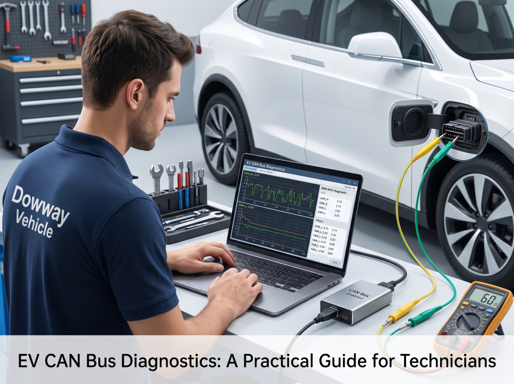
This guide covers how CAN works on an EV, how to use a CAN Box (analyzer), and how to pinpoint common network faults using simple tools.
1. Core Principles of the CAN Bus
The Controller Area Network (CAN) is a differential, serial bus system. It is designed to send data reliably in noisy, high-voltage vehicle environments.
1.1 The Physical Layer (ISO 11898-2 High-Speed CAN)
High-speed CAN uses two wires twisted together: CAN_H (CAN High) and CAN_L (CAN Low). The twist is important because it cancels out electromagnetic noise.
- Static Voltage States: When no data is being sent (recessive state), the lines sit at: $$\text{CAN\_H} \approx 2.7\text{ V}$$$$\text{CAN\_L} \approx 2.3\text{ V}$$ The differential voltage ($\text{CAN\_H} – \text{CAN\_L}$) is about $0.4\text{ V}$ (which translates to a dominant 0 state under specific network physical characteristics).
- Terminal Resistance: To keep signals from bouncing back and causing errors, there are two $120\,\Omega$ resistors at each end of the bus. Because they are wired in parallel, your multimeter should read about $60\,\Omega$ when you test the lines with the vehicle completely powered off.
1.2 Data Link Layer & Frame Structure (CAN 2.0B)
Modern EVs use the CAN 2.0B standard frame. Each frame has a few main parts:
- Arbitration Field: This holds the $11\text{-bit}$ CAN ID. Lower CAN ID numbers always get higher priority on the network.
- Data Field: This carries the actual message payload ($0$ to $8$ bytes). This is where controllers send real-time values like voltage, current, temperature, and motor torque.
- CRC & ACK Fields: These bits check for errors and confirm that nodes received the message safely.
1.3 EV-Specific Baud Rates (Communication Speeds)
EV networks use different speeds depending on what the wires are connected to:
- Powertrain CAN (HS-CAN): Runs at $500\text{ kbps}$. This connects critical parts like the Vehicle Control Unit (VCU), Battery Management System (BMS), Motor Control Unit (MCU), On-Board Charger (OBC), and DC/DC converter.
- Body / Comfort CAN: Runs at $125\text{ kbps}$ for less urgent signals.
- Charging CAN: Runs at $250\text{ kbps}$ and follows the GB/T 27930 standard to communicate with fast chargers.
2. What is a “CAN Box”?
A normal laptop cannot read raw differential CAN signals. A CAN Box (also called a CAN Analyzer) acts as the physical translator.
+--------------+   USB   +-------------+   DB9 / OBD   +----------------------+
| Diagnostic   | <=====> |   CAN Box   | <===========> | Vehicle CAN Network  |
| PC Software  |         | (Translator)|               | (BMS, MCU, VCU, etc.)|
+--------------+         +-------------+               +----------------------+
It takes the vehicle’s CAN signals and converts them to a USB format your computer can understand. This lets your diagnostic software talk directly to the onboard Electronic Control Units (ECUs).
Key Functions of a CAN Box:
- Reading and Clearing Fault Codes (DTCs): This lets you read or clear error codes stored in units like the BMS, MCU, or ABS.
- Live Data Stream Monitoring: It acts like a live medical monitor for the car, showing real-time changes in pack voltage, cell temperatures, motor speed, and accelerator pedal position.
To do this work, you need two things: tough, reliable hardware and professional software (like PCAN-View or factory workshop programs).
3. How to Connect and Configure a CAN Analyzer
Follow these steps to set up your diagnostic environment:
- Plug in the Hardware: Use a high-quality USB cable to connect the CAN Box to your PC. Connect the other end (usually a DB9 connector or an OBD-II plug) to the vehicle’s diagnostic port.
- Start the Software: Make sure the driver is installed on your computer. Open your analyzer software (like PCAN-View) and check that the computer recognizes the hardware.
- Set the Speed: Choose the correct baud rate in your settings. For EV powertrain diagnostics, this is almost always $500\text{ kbps}$. If you set this wrong, the tool cannot communicate and might trigger errors on the bus.
4. Troubleshooting Steps and Data Analysis
When you suspect a communication issue, use this step-by-step diagnostic workflow:
Step 1: Check the Wiring (Physical Layer)
Do not try to read software packets until you are sure the wiring is good.
- Power-Off Test: Turn the car off and disconnect the auxiliary $12\text{ V}$ battery. Measure the resistance across CAN_H and CAN_L. It should be around $60\,\Omega$.
- Power-On Test: Turn the vehicle on. Measure the voltage to ground for each line:
- $\text{CAN\_H}$ should float between $2.5\text{ V}$ and $3.5\text{ V}$.
- $\text{CAN\_L}$ should float between $1.5\text{ V}$ and $2.5\text{ V}$.
- The sum of both voltages ($\text{CAN\_H} + \text{CAN\_L}$) must equal roughly $5\text{ V}$.
Step 2: Capture Messages (Sniffing)
Once the wires check out, use tools like Vector CANoe / CANalyzer or a budget USB-CAN Analyzer to capture messages.
- Use filters to focus on the modules you care about. For example, filter for IDs between
0x1800and0x18FFto isolate battery management (BMS) data. - If you just need a quick check, an OBD scanner can read fault codes and basic values. If you suspect deeper hardware issues, use an oscilloscope to check the actual shape of the CAN_H and CAN_L waves.
Step 3: Decode the Data with a DBC File
Raw data looks like meaningless hexadecimal numbers. To read it, load the correct DBC database file into your analysis software.
- Translated Values: The software converts those hex numbers into real values like State of Charge (SOC), cell voltages, current, temperatures, and motor torque.
- What to Watch For: Watch the signals for consistent update rates (periodicity), tiny timing delays (jitter), out-of-range numbers, and error frames.
Step 4: Trace the Cause of Communication Failures
- Total Silence (No Messages): This means a controller has lost power, a fuse has blown, a wire is broken, or the transceiver chip is dead.
- Garbled Data or Jumping Signals: This points to outside electrical interference, a bad ground connection, or incorrect termination resistance.
- Too Many Error Frames: This is usually caused by different modules set to different baud rates, a failing module, or severe electrical noise issues.
5. Identifying Common Wiring Faults
Physical damage to the wires or modules shows up as very specific electrical readings. Use these rules to spot faults:
5.1 Terminal Resistor Faults
- Resistance is over $120\,\Omega$: One of the two termination resistors is disconnected or the line is broken on one end.
- Resistance is under $60\,\Omega$: There are extra resistors wired into the bus, or a component has a short circuit inside.
5.2 CAN_H Line Broken (Open Circuit)
- Voltages: $\text{CAN\_H} \approx 5\text{ V}$, $\text{CAN\_L} \approx 0\text{ V}$.
- Result: The differential signal drops to zero and communication stops completely.
5.3 CAN_L Line Broken (Open Circuit)
- Voltages: $\text{CAN\_L} \approx 5\text{ V}$, $\text{CAN\_H} \approx 0\text{ V}$.
- Result: The differential signal fails, causing a total communication blackout.
5.4 Electrical Noise or Poor Grounding
- Waveform: You will see sharp spikes on the oscilloscope, frequent CRC errors, and random lost data packets.
6. EV CAN Diagnostics Reference Table
Use this quick-reference table to match your multimeter readings to common network states:
| Line Status | CAN_H Voltage | CAN_L Voltage | Parallel Resistance | Network Condition |
|---|---|---|---|---|
| Normal Static (No Data) | $\approx 2.7\text{ V}$ | $\approx 2.3\text{ V}$ | $\approx 60\,\Omega$ | Good (Recessive State) |
| Normal Dynamic (Sending) | $2.5\text{ V} – 3.5\text{ V}$ | $1.5\text{ V} – 2.5\text{ V}$ | $\approx 60\,\Omega$ | Good (Dominant State Active) |
| One Resistor Broken | Normal | Normal | $> 120\,\Omega$ | Jittery Signal / Intermittent Lost Packets |
| Too Many Resistors / Short | Normal | Normal | $< 60\,\Omega$ | Distorted Signals / Weak Signal Strength |
| CAN_H Line Open Circuit | $\approx 5\text{ V}$ | $\approx 0\text{ V}$ | Varies / Unstable | Network Down |
| CAN_L Line Open Circuit | $\approx 0\text{ V}$ | $\approx 5\text{ V}$ | Varies / Unstable | Network Down |
| Bad Ground / Noise Fault | Sharp voltage spikes | Sharp voltage spikes | $\approx 60\,\Omega$ | High CRC Errors / Data Corruption |
7. Final Thoughts
Understanding both the physical wires and the digital messages is the secret to fixing EV communication issues quickly. By using a CAN Box, confirming termination resistance, and using DBC files to translate raw hex, you can find and fix even the trickiest electrical bugs in a vehicle.
Do you prefer using PCAN-View or full Vector software for your daily diagnostic work? What is the hardest CAN fault you have had to trace? Share your experiences in the comments below!