





Author: Johnny Liu, CEO at Dowwaye
Published Date: June 4, 2026
Category: Automotive Engineering / Brake-by-Wire / Functional Safety (ISO 26262)
Estimated Reading Time: 15 mins
0. Introduction: Removing the Hydraulic Safety Net
In the current era of electric vehicles and automated driving, the Electro-Mechanical Brake (EMB) is widely seen as the ultimate execution unit for brake-by-wire technology. However, it remains one of the most debated and challenging systems to engineer.
Traditional hydraulic braking systems take about $300\text{ ms}$ to $500\text{ ms}$ to build hydraulic pressure and squeeze the calipers after a driver presses the pedal. EMB eliminates hydraulic lines, master cylinders, and vacuum boosters entirely. By using electric motors at each wheel to squeeze the brake discs directly, EMB cuts this response time to under $100\text{ ms}$. At $120\text{ km/h}$, saving these few hundred milliseconds cuts stopping distance by nearly $10\text{ m}$. In an emergency, this is the difference between a safe stop and a fatal crash.
Yet, this shift to pure electrical signal transmission means the physical safety net is gone. Without hydraulic backups, braking reliability depends completely on the design quality of the electronic systems. A single power loss, bus failure, or software glitch could leave a vehicle with zero brakes. This is why functional safety design based on the ISO 26262 standard is the most critical pillar of EMB development.
At Dowwaye, our technical work with OEMs and Tier 1 suppliers shows that the battle over EMB is not just about mechanical hardware. It is about safety architectures and smart fail-degraded control algorithms. This article examines the functional safety design and fail-safe logic of EMB systems during the initial concept phase.
1. Item Definition & The Paradox of Homologous Calipers
Under ISO 26262, the functional safety process starts with the Item Definition. This step defines the physical boundaries, functional interfaces, and operating environments of the system. If you miss a single critical link here, your Hazard Analysis and Risk Assessment (HARA) will miss critical failure modes.
1.1 Physical Boundaries and Components
A standard four-wheel independent EMB system includes:
- Electronic Brake Pedal Unit: Features displacement and force sensors along with a pedal feel emulator to capture what the driver wants to do.
- Central Controller (Main ECU / Domain Controller): Decides how to distribute brake force and sends out control commands.
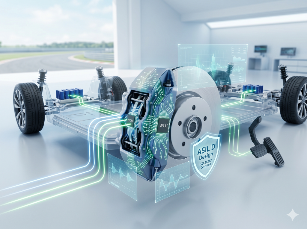
- Wheel-Side Caliper Actuators: Four independent EMB calipers, each with its own Wheel Control Unit (WCU), drive motor, reduction gear mechanism, and clamping force sensor.
- Power Supply System: Provides low-voltage electrical energy.
- Parking Brake Switch: Controls the Electronic Parking Brake (EPB) for auxiliary hold and emergency backup.
[Driver Pedal Input] -> [Electronic Brake Pedal (Dual-Channel)] -> [Main ECU (Dual-MCU Architecture)]
                                                                                  |
         +------------------+-----------------------+-----------------------+-----+------------------+
         |                  |                       |                       |                        |
         v                  v                       v                       v                        v
    [FL Caliper/WCU]   [FR Caliper/WCU]        [RL Caliper/WCU]        [RR Caliper/WCU]         [EPB Parking Lock]
1.2 Two Unique Physical Safety Characteristics of EMB
Unlike steer-by-wire (SbW) systems, which rely entirely on electronic redundancy because they lack a physical steering column, EMB has two unique mechanical features that shape its safety strategy:
Characteristic 1: Physical Isolation vs. The Homologous Paradox
Mechanically, the four EMB calipers sit on separate wheels with their own motors and gears. If one caliper jams, burns a winding, or breaks a gear, the damage is physically isolated. The other three wheels are unaffected. This offers much better fault isolation than a central hydraulic system, where a single master cylinder leak can drain the entire brake fluid reserve.
The catch is Common-Cause Failure (CCF). All four calipers share the exact same hardware, motor types, driver circuits, and WCU algorithms. If there is a systemic flaw—like a specific electromagnetic interference (EMI) pattern, a bad batch of semiconductors, or a hidden bug in the control code—all four calipers could fail at the exact same moment.
Even worse, a single failure in the upstream controller can disable all wheels instantly. If the central controller loses power or crashes, the physical isolation of the calipers does not matter; they will all lose their commands. System designers must use dual-MCU lockstep architectures, redundant power networks, and heterogeneous software to prevent these shared failures.
Characteristic 2: Mechanical Self-Locking as a Last Resort
If all electrical systems die and all electronics fail, EMB can still use the mechanical self-locking or high back-drive resistance of the wheel-side gears to hold a minimum level of deceleration or parking force. This provides a final mechanical line of defense to stop the car.
1.3 Functional Hierarchy
During the item definition phase, we organize the system’s operations into four functional layers to guide the HARA:
| Layer | Function | Core Responsibility |
|---|---|---|
| Layer 1 | Base Driving & Braking | Reads pedal inputs to drive the four calipers for basic stopping and parking. |
| Layer 2 | Brake Performance Tuning | Manages active safety systems like ABS, EBD, and ESC. |
| Layer 3 | Fault Tolerance & Degraded Control | Runs diagnostics, switches between fail-safe modes, and dynamically redistributes brake force. |
| Layer 4 | Vehicle Communication | Controls HMI warning lights, brake lights, and talks to the ADAS and body control units. |
2. HARA Analysis & Defining ASIL D Safety Goals
Hazard Analysis and Risk Assessment (HARA) is the core of the ISO 26262 concept phase. It grades safety risks from ASIL A to ASIL D by looking at Severity ($S$), Exposure ($E$), and Controllability ($C$).
2.1 HARA Risk Matrix
The ISO 26262 safety level is calculated using a simple relationship:$$\text{ASIL Grade} = f(S, E, C)$$
ASIL D is the highest and most rigorous level, while QM (Quality Management) means the risk does not require special functional safety measures.
2.2 Analyzing a High-Speed Braking Failure Scenario
Let us look at one of the worst-case scenarios for an EMB system: “A complete loss of all braking force while driving at $120\text{ km/h}$ on a highway.”
- Severity ($S$): A total brake loss at $120\text{ km/h}$ will almost certainly cause a high-speed collision with fatal injuries. This gets the maximum rating of $S3$.
- Exposure ($E$): Highway driving is a standard, daily routine for passenger cars. This receives the highest rating of $E4$.
- Controllability ($C$): If you lose all brakes at high speed, you cannot steer your way out of trouble easily. The driver cannot reliably control the hazard. This is rated $C3$.
Using the standard ISO 26262 risk matrix:
| Severity ($S$) | Exposure ($E$) | Controllability $C1$ | Controllability $C2$ | Controllability $C3$ |
|---|---|---|---|---|
| $S3$ | $E1$ | QM | ASIL A | ASIL B |
| $E2$ | ASIL A | ASIL B | ASIL C | |
| $E3$ | ASIL B | ASIL C | ASIL D | |
| $E4$ | ASIL C | ASIL D | ASIL D (Result) |
The combination of $S3 + E4 + C3$ results in an ASIL D rating. This means the EMB system must meet the highest engineering standards to prevent a total loss of braking force.
2.3 The Four Core Safety Goals
Based on our HARA, we establish four primary safety goals for the EMB system, all rated at ASIL D:
                              +----------------------------+
                              |   EMB Top Safety Goals     |
                              +----------------------------+
                                             |
         +-----------------------+-----------+-----------+-----------------------+
         |                       |                       |                       |
         v                       v                       v                       v
    [SG01: ASIL D]          [SG02: ASIL D]          [SG03: ASIL D]          [SG04: ASIL D]
 Prevent Unintended Loss   Prevent Unintended       Prevent Insufficient    Prevent Loss of
    of Braking Force       Braking Activation          Braking Force       Pedal Input Signals
- SG01: Prevent unintended loss of braking force (ASIL D)
- Requirement: If a single hardware component fails, the backup system must maintain basic braking within $\le 100\text{ ms}$ without interruption.
- SG02: Prevent unintended braking activation (ASIL D)
- Requirement: The system must prevent driver circuits or software bugs from accidentally locking a wheel. If this happens, the system must shut off power to that specific motor to prevent a high-speed spin.
- SG03: Prevent insufficient braking force (ASIL D)
- Requirement: The difference between the actual clamping force and what the driver wants must stay within safe limits.
- SG04: Prevent loss of brake pedal signals (ASIL D)
- Requirement: Pedal travel and force sensors must use different, independent backup designs so a single sensor failure does not lose the driver’s intent.
2.4 Three Safe States for Fail-Degraded Control
To meet these safety goals, the EMB software uses three operating modes. Through fault tree analysis (FTA), we make sure the total system failure rate across these modes stays below $< 10^{-8}/\text{h}$ to meet the ASIL D standard:
- Full-Function Mode: All parts run without issues, or with minor latent faults that do not affect performance. The system can survive at least one hardware failure and still deliver 100% braking power.
- Partial-Function Mode: A single hardware failure occurs (e.g., one caliper fails or a communication line cuts out). The system runs a force-reconstruction algorithm to keep the car stable and stopping safely.
- Emergency Mode: If a second hardware failure happens and all electronic backups are gone, the system relies on emergency measures. It uses the EPB or regenerative motor braking to bring the vehicle to a stop.
3. System-Level Architecture: Three-Way Parallel Safety & Power Backups
Once you have safety goals, you need an electrical and electronic (E/E) architecture that keeps the vehicle safe. We use a three-way parallel safety design: physical hardware backups, software verification, and clear human-machine communication.
+-------------------------------------------------------------------------+
|                  Three-Way Parallel Safety Architecture                   |
+-------------------------------------------------------------------------+
| [Line 1: Physical Hardware] -> Dual power, dual CAN, dual-channel pedal, |
|                                clamp force sensors.                     |
|                                                                         |
| [Line 2: Software Validation] -> Sensor plausibility, gate driver watch, |
|                                  state observers.                       |
|                                                                         |
| [Line 3: Human Interaction]    -> Live diagnostic codes, visual/audio    |
|                                  alerts to warn driver to take over.    |
+-------------------------------------------------------------------------+
3.1 The Three-Way Parallel Safety Architecture
Line 1: Physical Hardware Redundancy
Hardware is the foundation of the system.
- Power Redundancy: Uses independent dual power supplies (a 12V/48V hybrid setup). If one battery line fails, the backup line takes over immediately without losing braking power.
- Communication Redundancy: Dual CAN FD buses run in parallel. If one gets noisy or snaps, the other takes over with zero packet loss.
- Sensor Redundancy:
- Brake Pedal: Uses two displacement sensors and two force sensors with separate power chips and wiring connected to different pins on the main ECU.
- Actuators: Every caliper has two clamping force sensors and two motor temperature sensors to monitor actual clamping force ($F_{\text{clamp}}$) in real time.
Line 2: Software Validation
With redundant hardware signals in place, the software must watch for hidden faults.
- Plausibility Cross-Checks: The software compares pedal travel with the calculated equivalent pedal force. If they do not match, the software flags a sensor drift issue and ignores the bad channel.
- Driver Stage Monitoring: The WCU monitors inverter switching times and bus currents down to the microsecond. If a transistor shorts, it shuts down that motor driver instantly.
Line 3: Human Interaction
When a single failure drops the system into Partial-Function Mode, the human-machine interface (HMI) must show a yellow or red warning light alongside an audio alert. Even though the software is redistributing brake force to keep the car straight, the driver must know the system is running with limited performance so they can slow down and pull over.
3.2 Saving Costs with ASIL Decomposition
Building every single part of an EMB system to meet ASIL D is too expensive and complex. Instead, we use ASIL Decomposition under the ISO 26262 guidelines.
For example, we can split safety goal SG01 (prevent loss of braking, ASIL D) within the main ECU:$$\text{SG01 (ASIL D)} \rightarrow \text{Main Controller Control Algorithm } \text{ASIL B(D)} + \text{Independent Safety Monitor } \text{ASIL B(D)}$$
- Control Channel: Runs on an efficient, standard ASIL B processor, handling the main brake force calculations.
- Monitor Channel: Runs on a simple, highly reliable ASIL B(D) circuit to check if the control channel’s outputs are reasonable.
By combining two independent ASIL B elements, we achieve ASIL D safety at a much lower hardware cost.
3.3 Power Architecture: The Dual-Capacitor Network
EMB motors draw a lot of current during heavy braking, sometimes up to dozens of amperes. To handle this safely, we use a “low-voltage battery + dual-axle supercapacitor” setup.
  +------------------+             +--------------------+
  |  Low-Volt Bat    | <---------> |  DCDC Converter    |
  +------------------+             +--------------------+
           |                                  |
           v                                  v
  +------------------+             +--------------------+
  |  Power Branch 1  |             |  Power Branch 2    |
  +------------------+             +--------------------+
           |                                  |
           v                                  v
+-------------------------------------------------------+
|          Dual-Axle Supercapacitor Modules             |
|  - Supplies high transient current pulses.            |
|  - Provides energy for a final safe stop if the main  |
|    DCDC converter fails completely.                   |
+-------------------------------------------------------+
If the main DCDC converter or battery fails, supercapacitors placed near the front and rear axles discharge within milliseconds to supply enough power for one final, safe emergency stop.
4. Failure Modes, Clamping Ratios, and Brake Force Reconstruction
During the concept phase, the ultimate test is how the system handles a failure in real time.
4.1 The Four-Wheel Failure Factor ($\lambda_i$)
To turn complex physical faults into numbers the controller can understand, we use a failure factor ($\lambda_i$):$$\lambda_i = f(F_{\text{clamp}, i}, I_{\text{motor}, i})$$
Where:
- $i \in \{FL, FR, RL, RR\}$ (front-left, front-right, rear-left, rear-right).
- $F_{\text{clamp}, i}$ is the actual clamping force, and $I_{\text{motor}, i}$ is the motor current.
We define the factor as:
$$\lambda_i = \begin{cases} 1, & \text{Wheel is healthy} \ [0, 1), & \text{Brake force is degraded} \
1, & \text{Unintended braking (caliper is dragging or locked up)} \end{cases}$$
The main ECU compares clamping force with motor current to calculate $\lambda_i$ on the fly, using it to drive the fail-degraded control logic.
4.2 Dynamic Brake Force Reconstruction & Priority Strategy
If a wheel fails (for example, $\lambda_{RL} = 0$, meaning the rear-left brake is completely gone), the system starts reconstructing brake force within $20\text{ ms}$.
Failure Detected (e.g. λ_RL = 0)
   |
   v
[Brake Force Reconstruction Activated]
   |
   +--> Constraint 1: Front-to-Rear Balance (prevents vehicle pitching)
   +--> Constraint 2: Left-to-Right Balance (prevents pulling/yawing)
   +--> Constraint 3: Diagonal Symmetry (prevents spinning/tail-sliding)
The reconstruction algorithm tries to balance three physical constraints:
- Front-to-Rear balance: Prevents sudden vehicle pitching.
- Left-to-Right balance: Prevents pull and yaw that makes the car veer.
- Diagonal symmetry: Keeps the car from spinning on slippery roads.
In most real-world failures, you cannot satisfy all three constraints at once. The EMB safety controller uses a strict priority list:$$\text{Vehicle Stability (prevent rear wheel lockup/spin)} > \text{Braking Balance (prevent pull)} > \text{Total Brake Force} > \text{Cross-System Steering Help}$$
- Stability is priority number one: The system will sacrifice stopping distance and let the car take longer to stop if it means keeping the vehicle straight and preventing a spin.
- Handling Unintended Braking ($\lambda_i > 1$): If a caliper jams or a driver circuit shorts, causing a wheel to brake without a command, the vehicle will pull hard toward that side. The system uses a two-step fix: first, it cuts power to that caliper’s inverter within $10\text{ ms}$; second, it applies calculated braking to the other three wheels to create a counter-torque, keeping the car straight.
4.3 Multi-Wheel Failure Strategies
When multiple wheels fail, the system must balance vehicle stability against stopping power with fewer resources.
              +--------------------------+
              |   Multi-Stage Degraded   |
              +--------------------------+
                           |
       +-------------------+-------------------+
       |                   |                   |
       v                   v                   v
  [Single Wheel]       [Two Wheels]       [Three/Four Wheels]
Force Redistribution  Three Scenarios      Ultimate Emergency
       |                   |                   |
       v                   v                   v
 Rebalance remaining   Limit speed and      Regen motor brake,
     healthy wheels     maintain stability      EPB, and ADAS
1) The Three Scenarios of Two-Wheel Failure
- Scenario A: Same-Side Front and Rear Failure (Most Dangerous)
- Effect: You lose all braking on one side. Squeezing the other side creates a massive yaw moment, spinning the car instantly.
- Strategy: The system limits vehicle speed to under $40\text{ km/h}$. It heavily restricts braking force on the healthy side to keep the car straight, reducing total deceleration to about 20% of normal.
- Scenario B: Diagonal Cross Failure
- Effect: You have one working brake on the front axle and one on the rear, on opposite sides. The yaw forces partially cancel out.
- Strategy: The system allows medium-speed driving while adjusting wheel slip to keep the car stable and stopping straight.
- Scenario C: Same-Axle Failure (Front or Rear)
- Effect: Losing the front axle is dangerous because front wheels handle 60% to 70% of braking force during weight transfer. Relying only on the rear axle can easily lock the rear tires and cause a spin.
- Strategy: The system limits vehicle speed and forces the rear ABS into its highest safety setting to prevent lockups.
2) Three-Wheel and Four-Wheel Emergency Stops
- Three-Wheel Failure: Only one wheel can brake. This is not enough to stop safely. The system applies maximum safe force to that single wheel while calling on other chassis systems to help.
- Four-Wheel Failure: The EMB system has failed completely. The controller triggers its final backups:
- It engages the EPB on the rear axle to slow the car down mechanically.
- It commands the drive motors to use regenerative braking to slow the vehicle down electrically.
- It coordinates with the ADAS to guide the car to a safe stop along the shoulder.
5. Regulatory Compliance: Designing for China’s GB 21670-2025 Standard
Any EMB system must pass strict regulatory tests before it can hit the road. In China, the key standard is GB 21670-2025: Technical requirements and testing methods for passenger car braking systems, which went into effect on January 1, 2026.
               GB 21670-2025 Brake Standard Highlights
                                 |
         +-----------------------+-----------------------+
         |                                               |
         v                                               v
  [ETBS Classification]                          [5-Second Recovery Rule]
 EMB must meet ASIL D functional             Must recover effective braking within
      safety standards.                       5 seconds of a single power failure.
5.1 Formal Integration of ETBS
GB 21670-2025 officially covers Electric Transmission Braking Systems (ETBS) that lack hydraulic or pneumatic backups. It mandates that any vehicle with an ETBS must satisfy strict functional safety and electromagnetic compatibility (EMC) requirements, with core safety links designed to meet ASIL D standards.
5.2 The 5-Second Power Recovery Rule
The standard states that if a single point of power fails (like a battery disconnecting), the system must recover or maintain effective emergency braking within 5 seconds ($5\text{ s}$). The vehicle must still meet minimum deceleration requirements under this degraded state. This rule makes dual-power paths and supercapacitor backups a necessity.
5.3 Documentation Checklist for Type Approval
To pass regulatory audits, car manufacturers must submit a complete set of safety documents:
- System Description: Explains the system boundaries, hardware, and software layouts.
- HARA Report: Shows the step-by-step risk assessment leading to the ASIL D target.
- Safety Measures (FSR & TSR): Explains how the design handles and resolves failures.
- Safety Analysis (FMEA & FTA): Quantifies system failure rates and single-point risks.
- Validation Plan and Test Results: Proves the system works under real-world conditions.
6. Closing Thoughts
This article outlines the conceptual safety design of an EMB system—from system boundaries and HARA analysis to safety architectures and fail-degraded control logic. The concept phase answers the two most important questions: “What are we building?” and “Why are we building it this way?”
In our next piece, 《EMB Functional Safety (Part II): From Concept to Product Realization》, we will shift from theory to physical implementation. We will explore:
- Designing lockstep dual-MCU hardware for WCUs;
- Writing software for microsecond-level gate driver diagnostics;
- Executing physical fault injection tests in winter testing grounds.
As chassis technology moves to pure wire control, safety must be built into the core of the system. That is the only way EMB can safely make the leap from the lab to the road.
7. Deep FAQ (Quick Answers & Technical Details)
Q1: Why do EMB and Steer-by-Wire (SbW) use completely different safety architectures if both lack mechanical backups?
- Short Answer:SbW has only one physical rack to steer and must stack backups onto that single unit, while EMB has four physically separate calipers, making its main challenges preventing common-cause failures and balancing brake force.
- Technical Details:If SbW fails, the driver loses steering immediately. So, SbW uses highly concentrated redundancy on one physical unit—dual-wound motors, dual driver circuits, and dual controllers. EMB calipers are physically isolated, so one failing does not break the others. However, because the calipers are identical, they suffer from Common-Cause Failure (CCF) risks. EMB safety design focus is therefore on upstream controller separation, diverse software, and smart force reconstruction to use the healthy wheels to keep the car stable if one caliper fails or locks up.
Q2: How does a wheel lockup or “unintended braking” scenario get handled at $120\text{ km/h}$?
- Short Answer:The system cuts power to the bad caliper in under 10 milliseconds and uses the other three wheels to apply counter-braking, keeping the car straight.
- Technical Details:If a WCU circuit shorts and locks a caliper, the failure factor becomes $\lambda_i > 1$. The system reacts instantly:
- Kill the power: The WCU hardware safety monitor cuts power to the motor inverter within $10\text{ ms}$, letting the caliper release.
- Counter-torque braking: While the brake releases, the main controller reads the vehicle’s yaw rate and lateral acceleration. It applies precise braking to the healthy wheels on the opposite side to create a counter-torque, keeping the car in its lane.
Q3: Why is the HMI warning system considered a core functional safety mechanism rather than a basic display feature?
- Short Answer:HMI alerts warn the driver to slow down and pull over, which minimizes the time the vehicle drives around with a single failure before a second one occurs.
- Technical Details:If an EMB loses one of its dual batteries, the backup battery keeps the brakes working at 100%. The driver feels no difference. However, the system is now running without backups; the next failure will be catastrophic. The HMI warning tells the driver to pull over immediately. This reduces the Exposure ($E$) window—the time the vehicle operates in a vulnerable state—which is a core principle of ISO 26262 risk reduction.
Q4: Why is losing the front axle’s brakes so much harder to manage than losing the rear axle’s?
- Short Answer:The front wheels handle most of the braking weight transfer; if you lose them and try to stop using only the rear wheels, the rear tires will lock up and spin the car.
- Technical Details:When you brake, weight shifts forward, loading the front tires and unloading the rear tires. The front axle handles 60% to 70% of the stopping force. If the front brakes fail, the rear tires lack the grip to stop the car. Squeezing the rear brakes too hard will lock them up instantly, causing a severe spin. If the rear brakes fail instead, the front tires have plenty of grip to stop the car safely while maintaining steering control. Thus, front axle failure triggers extreme speed limits and strict rear ABS monitoring.
Q5: How does an EMB system meet the “5-second power recovery” rule in the new GB 21670-2025 standard?
- Short Answer:The hardware must use an ultra-fast smart power switch to swap battery lines and place supercapacitors near the calipers to keep voltage stable during the switch.
- Technical Details:If the main battery line drops, the EMB motors can lose power, causing the brake pads to pull back and lose braking. To pass the 5-second rule, the system uses:
- A Smart Power Distribution Unit (PDU): Switches power to the backup battery line in $\le 1\text{ ms}$.
- Supercapacitors: Placed right next to the front and rear axle controllers. They act as local energy reserves, keeping the motors powered during the millisecond-level switchover so brake pressure never drops.