





- Author: Johnny Liu (CEO at Dowway Vehicle)
- Published Date: June 30, 2026
- Academic Citation & Acknowledgement: This piece builds upon technical findings and data published on June 12, 2026, by Li Quandang (Senior Engineer at the New Energy Vehicle Technology Research Institute).
- Reading Time: 8 minutes
Table of Contents
TL;DR
The Controller Area Network (CAN Bus) is a shared-wire communication system that lets electronic control units (ECUs) talk to each other without a central computer. It uses differential signaling to block noise, resolves data collisions smoothly via message ID priorities, and features built-in hardware error tracking that shuts down faulty nodes automatically to keep the rest of the system safe.
1. What is a CAN Bus?
Think about how many sensors and controllers run inside a car or an industrial robot today. If every sensor needed a dedicated wire to connect to every computer, the vehicle would be packed with hundreds of pounds of copper cabling.
This is where the CAN Bus comes in. Developed by Bosch in the 1980s, CAN replaces messy point-to-point wiring with a shared “information highway.”
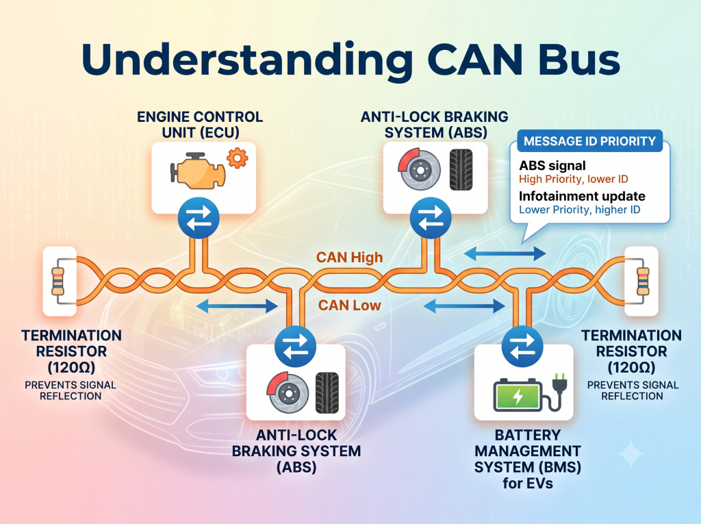
On this single network, devices like the Engine Control Unit (ECU), ABS, instrument cluster, and Battery Management System (BMS) all send and receive data packets over the same set of wires. It simplifies wiring, cuts down costs, and reduces system weight.
2. Main Features of CAN Bus
Several key designs make CAN the top choice for harsh, real-time setups.
A. Multi-Master Setup (No Central Host)
In a CAN network, all nodes are equal. There is no master computer telling other devices when to talk. When the line is free, any node can start sending data. If one node breaks, the rest of the network keeps running without missing a beat.
B. Message ID Addressing (Content Over Destination)
Unlike Ethernet or IP networks, CAN does not use device addresses. Instead, it tags every message with a unique Message ID that describes the data itself.
All nodes hear the message. They use hardware filters to decide whether to read it or ignore it. This means one transmission can update multiple parts of the system at the same time.
| Message ID | Data Content | Practical Use Case |
| 0x100 | Engine Speed | Sends real-time RPM to dashboard and transmission |
| 0x101 | Vehicle Speed | Sends speed data to HUD, ABS, and power steering |
| 0x200 | Battery Voltage | BMS broadcasts pack voltage to the main motor controller |
| 0x300 | Temperature | Sends thermal readings to battery cooling fans and HVAC |
C. Collision-Free (Non-Destructive) Arbitration
When multiple nodes try to talk at once, CAN uses Message IDs to decide who goes first without losing any data.
In CAN logic:
- 0 is a Dominant Bit (strong).
- 1 is a Recessive Bit (weak).
As nodes send data bit-by-bit, they monitor the wire. If a node sends a 1 (weak) but reads a 0 (strong) on the line, it knows a higher-priority message is going through. It stops sending immediately and switches to listening. The message with the lower ID number always wins and goes through without any delay or corruption.
Arbitration Example:
| Node | Attempted ID | Priority Level | Outcome |
| Node C | 0x080 | Highest | Wins; sends entire message without delay |
| Node A | 0x100 | Medium | Backs off mid-way; tries again later |
| Node B | 0x200 | Lowest | Backs off early; tries again later |
D. True Real-Time Speed
By giving safety systems (like brakes or battery monitors) the lowest ID numbers, engineers guarantee they get immediate access to the network. This makes CAN perfect for quick-reaction control loops.
E. Great Noise Immunity (Differential Signaling)
Cars and factory floors are full of electrical noise. CAN handles this by using two wires: CAN_H (High) and CAN_L (Low).
The receiver measures the voltage gap between the two wires:
If electromagnetic noise strikes the cable, it changes the voltage on both wires equally. Because the receiver only cares about the difference between them, the noise cancels out completely.
F. Hardware-Level Error Checks
CAN has built-in verification routines, including:
- Checksums (CRC)
- Bit monitoring
- Format checks
- Automatic ACK signaling
If a node runs into a physical issue, it tracks its own errors and steps aside before it can disrupt the rest of the bus.
3. The Physical Layer: Voltages and Resistors
To keep data flowing smoothly, the physical wires must meet specific standards.
Voltage Levels: Dominant vs. Recessive
The physical states on the wire map directly to binary data:
| Logical State | Bit Value | CAN_H Voltage | CAN_L Voltage | Differential Voltage (Vdiff) |
| Recessive | 1 | |||
| Dominant | 0 |
The Termination Resistors
You must place a resistor at the two far ends of the main line.
- Why? Electrical signals travel fast. When they hit the end of an open wire, they bounce back like an echo, distorting the next bits.
- The Fix: The
resistors match the physical properties of the twisted-pair wire, absorbing the signal energy and keeping the line clear.
- Note: Only put these at the two ends of the network—never on individual branch nodes, as too many resistors will draw too much current.
4. Error Checking and Self-Isolation
CAN’s high reliability comes from how it handles glitches and broken nodes.
Five Ways CAN Finds Errors
- CRC Error: The receiver recalculates the message checksum. If it doesn’t match the sent value, it flags an error.
- Bit Error: The sender reads the line as it talks. If it sends a dominant bit but reads a recessive one (or vice versa), it stops.
- Stuffing Error: To keep clocks in sync, CAN inserts an opposite bit after 5 identical bits in a row. If a node sees 6 identical bits in a row, it flags an error.
- Form Error: Fixed-format fields (like delimiters) must be recessive. If they show up as dominant, it is a form error.
- ACK Error: Receivers must pull the ACK slot dominant to confirm receipt. If they don’t, the sender flags an ACK error.
Self-Quarantine States
Every node has two internal counters: the Transmit Error Counter (TEC) and the Receive Error Counter (REC). Based on these numbers, a node operates in one of three states:
- Error-Active (Normal): The node communicates normally. When it finds an error, it sends an Active Error Flag (6 dominant bits) to force everyone to discard the bad frame.
- Error-Passive (Restricted): If errors pile up, the node enters this state. It can still talk but can only send Passive Error Flags (6 recessive bits), meaning it cannot interrupt healthy nodes.
- Bus-Off (Isolated): If the node keeps failing (TEC goes past 255), the controller cuts the node off from the physical wire completely, ensuring a physically damaged chip cannot block the rest of the system.
5. Pros and Cons of Classic CAN
The Good
- Highly Flexible: Easy to add or remove nodes without changing the whole setup.
- Guaranteed Timing: Priority-based design keeps safety systems fast and predictable.
- Tough: Built-in noise resistance and automatic node shut-offs protect the system.
- Cheap: Uses a simple, lightweight pair of wires.
The Bad
- Small Payload: Classic CAN can only carry 8 bytes of data per frame.
- Speed Limit: Top speed is 1 Mbps, which drops on longer runs.
- Traffic Delays: Under heavy loads, low-priority messages get pushed back.
- Layout Sensitive: Requires proper cable termination and clean routing.
6. Where is CAN Bus Used?
- Automotive: Links powertrain components, safety systems, ADAS, and body electronics.
- Electric Vehicles (EVs): Connects Battery Management Systems (BMS) to motor controllers and charging ports.
- Factories & Robotics: Coordinates motors, sensors, and arm actuators.
- Heavy Machinery: Runs systems in construction trucks, tractors, and marine vessels.
7. The Next Step: CAN FD (Flexible Data-rate)
As modern vehicles and smart factories demand more data, classic CAN is reaching its limits. To keep up, engineers use CAN FD.
Key Improvements
- More Data: The payload jumps from 8 bytes to 64 bytes per frame, cutting down on packaging overhead.
- Two Speeds: It uses standard speed (up to 1 Mbps) during arbitration to avoid collisions, but switches to high-speed (often 5 Mbps or more) to send the actual data payload.
Classic CAN Frame:
┌─────────────────┬───────────────────┬──────────────┐
│ Arbitration 1M │ Data (8 Bytes) │ CRC / ACK │ <– All at 1 Mbps
└─────────────────┴───────────────────┴──────────────┘
CAN FD Frame:
┌─────────────────┬─────────────────────────────────────────────────┬──────────────┐
│ Arbitration 1M │ Data (Up to 64 Bytes) @ 5 Mbps │ CRC / ACK │
└─────────────────┴─────────────────────────────────────────────────┴──────────────┘
▲──────────────────────────────────────────────▲
High-Speed Payload Phase
Typical Uses for CAN FD
- EV Battery Packs: Helps stream high-density sensor readings from thousands of battery cells.
- ECU Updates: Speeds up firmware flashing during manufacturing or servicing.
- ADAS: Coordinates fast radar, lidar, and camera sensor arrays.
8. The Bottom Line
CAN Bus remains the go-to standard for a reason. By mixing a simple shared wire design with smart priority rules, noise canceling, and automatic safety shut-offs, it delivers cheap, reliable, and real-time communication.
Classic CAN still handles basic tasks perfectly, while CAN FD steps up to handle high-speed demands, showing that this protocol family is here to stay.
FAQ (Common Questions Answered)
Q1: Why does a CAN bus need termination resistors?
Short Answer: To absorb electrical signal echoes and prevent data corruption.
More Details: Without a resistor at each end of the bus, signals reflect back down the wire when they hit the end of the cable, creating noise that corrupts the incoming data.
Q2: What is the difference between dominant and recessive bits?
Short Answer: Dominant bits (0) override recessive bits (1) on the wire.
More Details: A dominant bit uses an active voltage difference of across the lines, while a recessive bit is an idle state where both lines float at
. If two nodes send different bits at the same time, the dominant bit (0) wins out.
Q3: How does CAN resolve data collisions?
Short Answer: Through priority-based ID comparison.
More Details: Nodes monitor the bus while transmitting their Message ID. If a node sends a recessive bit but reads a dominant bit, it realizes a higher-priority node (with a lower ID number) is transmitting and steps aside.
Q4: Can classic CAN and CAN FD nodes share the same physical wire?
Short Answer: No, they cannot talk on the same line without a bridge.
More Details: If a classic CAN controller hears the high-speed data phase of a CAN FD frame, it will read it as a format error and send an error flag, which can disrupt or crash the entire network.