





Published on: June 22, 2026
Author: Johnny Liu, CEO at Dowway Vehicle
Table of Contents
Quick Core Summary
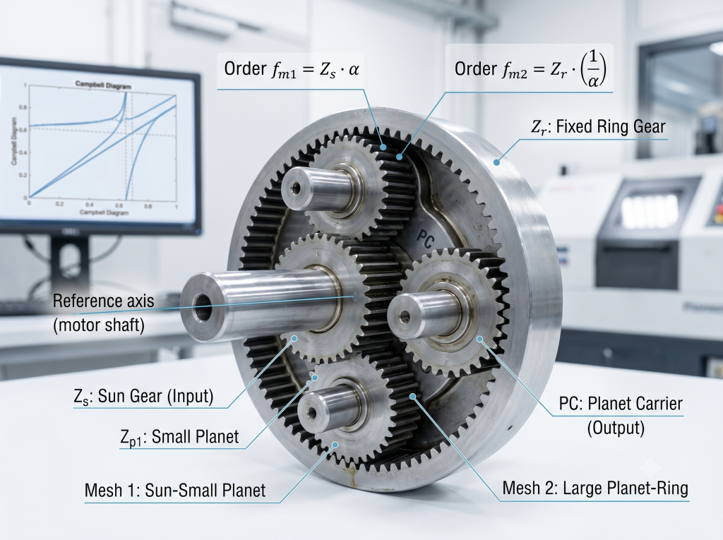
- What is an NW Coaxial Planetary Reducer? An NW configuration is a double-stage coaxial planetary gear system. It uses double-jointed (stepped) planet gears—a small planet $z_{p1}$ and a large planet $z_{p2}$ on a single rigid shaft—meshing with a central sun gear ($z_s$) and a fixed outer ring gear ($z_r$).
- What are the two core meshing orders? When the ring gear is stationary ($n_r = 0$) and we use the sun gear shaft as our reference:
- First Meshing Order ($O_1$, Sun-to-Small Planet): $O_1 = z_s \cdot \frac{k}{1+k}$
- Second Meshing Order ($O_2$, Large Planet-to-Ring): $O_2 = \frac{z_r}{1+k}$
- What is the NW Characteristic Coefficient ($k$)? It is the key structural ratio of the system: $$k = \frac{z_{p1} \cdot z_r}{z_s \cdot z_{p2}}$$
1. Introduction: Coaxial Electric Drivetrains and the NVH Challenge
Compact spaces in electric vehicles (EVs) have pushed carmakers to use coaxial electric drives. By lining up the motor shaft, the gears, and the wheel axle along one center line, we get highly compact drive units.
But this tight setup creates a major issue: high-frequency gear whine. Modern EV motors spin fast, often past $16,000 \text{ rpm}$ or even $20,000 \text{ rpm}$. The high-frequency vibrations from the gear teeth can easily pass into the cabin as a loud, high-pitched scream.
To track and fix this noise, NVH (Noise, Vibration, and Harshness) engineers use Order Analysis. This method links vibration frequencies directly to the speed of a reference shaft, which is usually the motor output/sun gear shaft.
In this guide, we will walk through the math and physics behind the two main meshing orders ($O_1$ and $O_2$) of the NW planetary reducer.
2. Inside the NW Planetary Design
To find our noise frequencies, we first need to look at the gear setup. The NW design uses a double-jointed (stepped) planet gear. This creates two gear meshes in a row:
                  [Fixed Ring Gear (zr)]
                         |
  [Sun Gear (zs)] ---> [Small Planet (zp1)] ===Rigid Shaft=== [Large Planet (zp2)]
                               |
                     [Planet Carrier (pc)]
Here are our gear teeth labels:
- $z_s$: Tooth count of the central Sun Gear.
- $z_{p1}$: Tooth count of the Small Planet Gear, which meshes with the Sun.
- $z_{p2}$: Tooth count of the Large Planet Gear, which is fixed to $z_{p1}$ on the same shaft.
- $z_r$: Tooth count of the fixed outer Ring Gear, which meshes with $z_{p2}$.
How the parts move:
- The Sun Gear ($z_s$) is the fast input shaft, spinning at speed $n_s$ ($\text{rpm}$).
- The Ring Gear ($z_r$) is bolted to the housing, so its speed $n_r = 0 \text{ rpm}$.
- The Planet Carrier (PC) is the slower output shaft, spinning at speed $n_{pc}$ ($\text{rpm}$).
- The planet gears ($z_{p1}$ and $z_{p2}$) do two things at once: they spin on their own pin (self-rotation) while traveling around the sun gear (revolution).
This layout gives us two separate tooth-mesh contact points:
- First-Stage Mesh: Where the Sun Gear ($z_s$) meets the Small Planet ($z_{p1}$).
- Second-Stage Mesh: Where the Large Planet ($z_{p2}$) meets the fixed Ring Gear ($z_r$).
3. Basic Speed Formulas & The NW Coefficient ($k$)
Before we find the orders, we must set up our speed relationships.
3.1 The NW Characteristic Coefficient ($k$)
The NW system relies on a structural design number called the NW Characteristic Coefficient, written as $k$. It depends entirely on the gear tooth counts:$$k = \frac{z_{p1} \cdot z_r}{z_s \cdot z_{p2}}$$
This number links the speeds across both gear stages.
3.2 Finding the Planet Carrier Speed ($n_{pc}$)
The carrier holds the spinning planet gears. When the ring gear is held still ($n_r = 0$), we calculate the carrier speed ($n_{pc}$) like this:$$n_{pc} = \frac{n_s}{1 + k}$$
- $n_s$ is the input speed of the sun gear.
- $k$ is the design coefficient we just defined.
4. Deriving the First Meshing Order ($O_1$) Step-by-Step
The first noise source ($O_1$) comes from the contact between the Sun Gear ($z_s$) and the Small Planet Gear ($z_{p1}$).
Our core order equation is: $$\text{Order } (O) = \frac{\text{Mesh Frequency } (f_m)}{\text{Reference Axis Frequency } (N_{ref})}$$
We will use the Sun Gear Shaft as our reference axis. Its speed frequency $N_s$ in Hz (turns per second) is: $$N_s = \frac{n_s}{60}$$
Step 4.1: Find the Relative Spin Speed of the Planet Gear ($n_{p1}$)
Because the carrier is also moving, we cannot just use absolute speeds. We must find how fast the planet gear spins relative to the carrier.
If the carrier stood still, the planet would spin at $n_s \cdot \frac{z_s}{z_{p1}}$. But because the carrier spins at $n_{pc}$, we subtract the carrier speed to get the relative speed:$$n_{p1} = (n_s – n_{pc}) \cdot \frac{z_s}{z_{p1}}$$
Step 4.2: Write $n_{p1}$ Using Sun Speed $n_s$ and $k$
Now, put the carrier speed formula ($n_{pc} = \frac{n_s}{1+k}$) into our speed equation:$$n_{p1} = \left( n_s – \frac{n_s}{1+k} \right) \cdot \frac{z_s}{z_{p1}}$$
Pull $n_s$ out of the parenthesis:$$n_{p1} = n_s \cdot \left( 1 – \frac{1}{1+k} \right) \cdot \frac{z_s}{z_{p1}}$$
Simplify the fraction: $\left(1 – \frac{1}{1+k}\right) = \frac{k}{1+k}$. This gives us:$$n_{p1} = n_s \cdot \left( \frac{k}{1+k} \right) \cdot \frac{z_s}{z_{p1}}$$
Step 4.3: Find the Planet Spin Frequency ($N_{p1}$)
Divide the RPM speed $n_{p1}$ by 60 to get the frequency in Hz:$$N_{p1} = \frac{n_{p1}}{60} = \frac{n_s}{60} \cdot \left( \frac{k}{1+k} \right) \cdot \frac{z_s}{z_{p1}}$$
Step 4.4: Find the First-Stage Meshing Frequency ($f_{m1}$)
The mesh frequency is how fast individual teeth meet. Multiply the relative spin frequency of the planet gear by its own tooth count ($z_{p1}$):$$f_{m1} = N_{p1} \cdot z_{p1}$$
Put the $N_{p1}$ formula in place:$$f_{m1} = \left[ \frac{n_s}{60} \cdot \left( \frac{k}{1+k} \right) \cdot \frac{z_s}{z_{p1}} \right] \cdot z_{p1}$$
The $z_{p1}$ terms cancel out completely:$$f_{m1} = \frac{n_s}{60} \cdot z_s \cdot \left( \frac{k}{1+k} \right)$$
Step 4.5: Find the Final Order $O_1$
Divide the mesh frequency $f_{m1}$ by our reference speed $N_s = \frac{n_s}{60}$:$$O_1 = \frac{f_{m1}}{N_s} = \frac{\frac{n_s}{60} \cdot z_s \cdot \left( \frac{k}{1+k} \right)}{\frac{n_s}{60}}$$
The speed terms cancel out. We get our first final order, $O_1$:$$O_1 = z_s \cdot \frac{k}{1+k}$$
5. Deriving the Second Meshing Order ($O_2$) Step-by-Step
Our second noise source ($O_2$) comes from the contact between the Large Planet Gear ($z_{p2}$) and the Fixed Ring Gear ($z_r$).
Step 5.1: Define the Large Planet Gear Speed ($n_{p2}$)
Since both planet gears sit on the same physical shaft, they must spin at the exact same speed:$$n_{p2} = n_{p1}$$
Using our speed formula from Step 4.2:$$n_{p2} = n_s \cdot \left( \frac{k}{1+k} \right) \cdot \frac{z_s}{z_{p1}}$$
Step 5.2: Convert to Frequency ($N_{p2}$)
$$N_{p2} = \frac{n_{p2}}{60} = \frac{n_s}{60} \cdot \left( \frac{k}{1+k} \right) \cdot \frac{z_s}{z_{p1}}$$
Step 5.3: Find the Second-Stage Meshing Frequency ($f_{m2}$)
Multiply the spin frequency of the large planet gear by its tooth count ($z_{p2}$):$$f_{m2} = N_{p2} \cdot z_{p2}$$
Put the frequency formula in place:$$f_{m2} = \left[ \frac{n_s}{60} \cdot \left( \frac{k}{1+k} \right) \cdot \frac{z_s}{z_{p1}} \right] \cdot z_{p2}$$
Rearrange the terms:$$f_{m2} = \frac{n_s}{60} \cdot \left( \frac{k}{1+k} \right) \cdot \left( \frac{z_s \cdot z_{p2}}{z_{p1}} \right)$$
Step 5.4: Simplify Using Coefficient $k$
Remember our definition of $k$: $$k = \frac{z_{p1} \cdot z_r}{z_s \cdot z_{p2}}$$
We can turn the tooth fraction upside down to get this match: $$\frac{z_s \cdot z_{p2}}{z_{p1}} = \frac{z_r}{k}$$
Put $\frac{z_r}{k}$ back into our $f_{m2}$ formula:$$f_{m2} = \frac{n_s}{60} \cdot \left( \frac{k}{1+k} \right) \cdot \left( \frac{z_r}{k} \right)$$
The letter $k$ cancels out:$$f_{m2} = \frac{n_s}{60} \cdot \frac{z_r}{1 + k}$$
Step 5.5: Find the Final Order $O_2$
Divide the mesh frequency $f_{m2}$ by our reference speed $N_s = \frac{n_s}{60}$:$$O_2 = \frac{f_{m2}}{N_s} = \frac{\frac{n_s}{60} \cdot \frac{z_r}{1 + k}}{\frac{n_s}{60}}$$
The speed terms cancel out, leaving us with our second final order, $O_2$:$$O_2 = \frac{z_r}{1 + k}$$
6. Symmetrical Design Rules
The final formulas show a beautiful mathematical balance in the NW design:
- First Mesh Order ($O_1$): Sun teeth $z_s$ times the ratio $\frac{k}{1+k}$.
- Second Mesh Order ($O_2$): Ring teeth $z_r$ times the inverse ratio $\frac{1}{1+k}$.
7. How We Use This to Stop Gear Whine
At Dowway Vehicle, we use these exact calculations during the early design phase of our electric drives. Knowing these numbers is crucial for two main tasks:
- Campbell Diagram Layouts: We map these orders ($O_1$ and $O_2$) to see exactly which motor speeds will trigger structural resonances in the gearbox housing. This helps us design stiffer brackets and cases to prevent loud cabin noises.
- Motor Wave Matching: Electric motors produce magnetic forces at specific frequencies. If the gear mesh orders ($O_1$ or $O_2$) match these motor force frequencies, they can multiply the noise, making it unbearable. Calculating these orders early lets us change tooth counts ($z_s, z_{p1}, z_{p2}, z_r$) to keep the frequencies apart.
8. FAQ
Q: Why do we subtract the carrier speed ($n_{pc}$) when calculating the planet gear spin?
To isolate the relative speed. The planet gear sits on a spinning carrier. Its true teeth-meshing rate depends on how fast the sun gear spins compared to the carrier, not how fast the sun gear spins relative to the ground. Subtracting $n_{pc}$ gives us this relative speed.
Q: What happens to the orders if the ring gear rotates instead of staying fixed?
Both orders will change. A rotating ring gear adds another moving part to the equation. The simple carrier speed formula ($n_{pc} = n_s / (1+k)$) stops working, and you must use Willis’ equations to recalculate the relative speeds.
Q: How do double-jointed planet gears affect noise compared to simple single-stage systems?
They create two high-energy noise points instead of one. Stepped planets give you high reduction ratios in a small space, but they create two different meshing frequencies ($O_1$ and $O_2$) that you have to manage.
About the Author: Johnny Liu is the CEO at Dowway Vehicle, a company focused on high-efficiency electric vehicle drivetrains. Johnny has spent years working on NVH problems, gearbox designs, and mechanical systems.
Do you need help calculating the noise profile of your gearbox design? Leave a comment below with your gear teeth counts ($z_s, z_{p1}, z_{p2}, z_r$) and our team will help you find your system’s critical frequencies!