





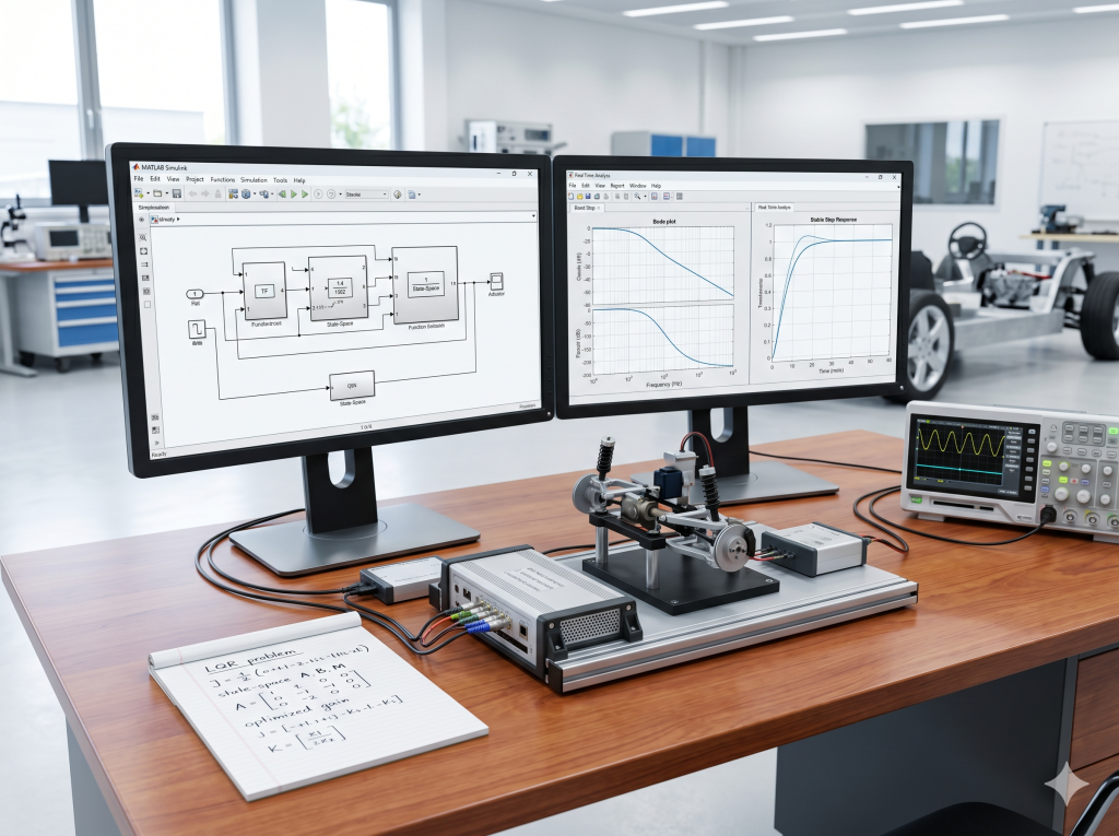
- Author: Johnny Liu, CEO at Dowway Vehicle
- Published Date: April 29, 2026
- Category: Control Systems / Automotive Engineering / Simulation
About the Author
I am Johnny Liu, the CEO of Dowway Vehicle. We build clean power drivetrains and smart vehicle dynamics. For over twenty years, I have worked on active car suspensions, drive-by-wire steering, and chassis safety. In our shop, we never build a physical part without testing it on a screen first.
Simulink helps us do that. It lets us run safety tests and try new control algorithms before we bend any metal. In this guide, I will share the exact workflows we use to model, analyze, and control dynamic systems.
Table of Contents
Part 1: Control System Theory
We must understand the math before we start dragging blocks around. Control theory splits models into three main forms.
1.1 Mathematical Modeling
A dynamic model shows how a system’s state and outputs change over time when you apply an input.
1. Input-Output Models
- Differential Equations: These write out the physical laws of the system in the time domain. Examples include mass-spring systems or electrical networks.
- Transfer Functions (TF): We get these by applying the Laplace transform to linear, time-invariant (LTI) differential equations, assuming all starting conditions are zero: $$G(s) = \frac{Y(s)}{U(s)} = \frac{b_m s^m + b_{m-1} s^{m-1} + \dots + b_0}{a_n s^n + a_{n-1} s^{n-1} + \dots + a_0}$$
- Frequency Characteristics: We get these by switching $s$ with $j\omega$ in the transfer function. This shows how the system responds to sine-wave inputs at different speeds.
2. State-Space Models
Modern control theory uses state-space models. Instead of treating the system like a hidden box, we track internal variables called states. These states define the energy and behavior of the system at any moment: $$\dot{x}(t) = Ax(t) + Bu(t)$$$$y(t) = Cx(t) + Du(t)$$
Where:
- $x(t)$ is the state vector.
- $u(t)$ is the input vector.
- $y(t)$ is the output vector.
- $A$ is the system matrix (it governs internal dynamics).
- $B$ is the input matrix (it shows how inputs affect the states).
- $C$ is the output matrix (it maps states to the measured outputs).
- $D$ is the direct feedthrough matrix.
Here is how Transfer Functions and State-Space Models compare:
| Feature | Transfer Function (TF) | State-Space (SS) |
|---|---|---|
| System Compatibility | Only works for Single-Input Single-Output (SISO) and Linear Time-Invariant (LTI) setups. | Works for Multi-Input Multi-Output (MIMO), non-linear, and time-varying setups. |
| Uniqueness | Unique for any given input-output pair. | Non-unique. You can choose different states, which changes your matrices. |
| Completeness | Only shows the controllable parts. Pole-zero cancellations hide hidden dynamics. | Shows everything. It covers both controllable and uncontrollable parts, plus observable and unobservable parts. |
| Computation | Uses frequency domain algebra. | Suited for computers and linear algebra solvers. |
3. Block Diagrams
We connect physical systems using three simple layouts:
- Series (Cascade): The transfer functions multiply: $G_{\text{total}}(s) = G_1(s) \cdot G_2(s)$
- Parallel: The transfer functions add up: $G_{\text{total}}(s) = G_1(s) + G_2(s)$
- Feedback: The formula for closed-loop feedback $H(s)$ is: $$G_{\text{closed}}(s) = \frac{G(s)}{1 \mp G(s)H(s)}$$
System Performance Markers
When we run step tests, we judge transient performance using four numbers:
- Overshoot ($M_p$): The peak value compared to the final steady value, written as a percentage: $$M_p = \frac{y(t_p) – y(\infty)}{y(\infty)} \times 100\%$$
- Settling Time ($t_s$): The time it takes for the system to settle and stay within a small error band (usually $2\%$ or $5\%$) of its final value.
- Peak Time ($t_p$): The time required to hit the very first overshoot peak.
- Rise Time ($t_r$): The time it takes to go from $10\%$ to $90\%$ (or $0\%$ to $100\%$) of the final value.
1.2 Analysis Methods
We have to test how stable a system is before we build a controller.
1. Time-Domain Analysis
We apply standard test signals to the system. These include unit impulse, unit step, unit ramp, unit acceleration, or unit sine waves.
- Stability Rule: An LTI system is stable if all its poles (the roots of the denominator) have negative real parts. If even one pole sits on the right side of the s-plane, the system will blow up.
- MATLAB tools:
zpk: Defines a zero-pole-gain system.roots: Finds the roots of your denominator to check pole locations.
2. Root Locus Analysis
We plot how the closed-loop poles move in the s-plane as we turn the gain ($K$) from $0$ to $\infty$.
- Two rules must match for any point on the plot:
- Magnitude Condition: $|K G(s)H(s)| = 1$
- Phase Condition: $\angle G(s)H(s) = (2k+1)\pi$
- MATLAB tools: Use
rlocus(sys)to draw the lines. Always useaxis equalright after so the horizontal and vertical axes use the same scale. This keeps your angles looking correct.
3. Frequency-Domain Analysis
We check how a system handles steady sine waves at different frequencies.
- The Plots:
- Nyquist Plot: A polar plot of $G(j\omega)$ as frequency ($\omega$) goes from $-\infty$ to $+\infty$.
- Bode Plot: Two separate graphs. The top one shows magnitude in decibels ($20\log_{10}|G(j\omega)|$). The bottom one shows the phase angle in degrees.
- Nichols Plot: This puts both Bode graphs onto one screen. It plots decibels directly against phase angle, using frequency as a hidden marker along the line.
- MATLAB tools: Use
nyquist(),bode(), andnichols(). - Key Numbers: Resonant peak ($M_r$), resonant frequency ($\omega_r$), bandwidth, and zero-frequency gain.
- Stability Checks (Nyquist Rule): Your system is stable if the Nyquist line circles the point $(-1, j0)$ in a counterclockwise direction $N$ times, where $N$ equals your number of unstable open-loop poles ($P$).
- Gain Margin ($G_M$): How much extra gain you can add before the system goes unstable.
- Phase Margin ($\Phi_M$): The extra phase delay needed to make the system unstable.
- MATLAB command:
margin(sys)calculates these safety margins for you.
4. State-Space Analysis
We use matrices to study complex systems with many inputs and outputs.
- Standard Forms: You can map a single transfer function to different state-space layouts using a transformation matrix ($x = Pz$). The four primary configurations are:
- Controllable Canonical Form (helps design state-feedback controllers).
- Observable Canonical Form (helps build state estimators).
- Diagonal Canonical Form (uncoupled states along the diagonal, used when poles are distinct).
- Jordan Canonical Form (used when poles repeat).
- MATLAB commands:
ss(),tf2ss(),zp2ss(),canon(), andjordan().
- Lyapunov Stability: A system is stable if we can find a positive-definite energy function $V(x)$ whose derivative over time, $\dot{V}(x)$, is always negative. For linear systems, we solve the Lyapunov Equation: $$A^T P + P A = -Q$$ If we choose any positive-definite matrix $Q$ and get a unique, positive-definite matrix $P$, our system is stable.
- MATLAB commands:
lyap(A, Q)orlyap2()solve this equation.
- MATLAB commands:
Part 2: Simulink Simulation Blocks
Now let us look at the blocks we use to build these systems in Simulink.
2.1 The Standard Block Library
1. Continuous Sub-library
This is where we build continuous-time models.
- State-Space Block: Computes $\dot{x} = Ax+Bu$ and $y=Cx+Du$. You must enter Matrix A, B, C, and D, along with the starting state vector $x_0$.
- Transfer Fcn Block: You enter the numerator (num) and denominator (den) vectors as descending powers of $s$.
- Zero-Pole-Gain Block: You enter the arrays for zeros (z), poles (p), and the gain constant (K).
- PID Controller Blocks (1-DOF & 2-DOF): These blocks compute proportional, integral, and derivative terms.
- Parameters: You configure the controller type, its form (Parallel or Ideal), the time domain, coefficients ($P, I, D$), and the filter constant ($N$). You can set start states and turn on upper and lower saturation limits to stop integrator windup. Under the Data Types tab, you can set boundaries. By default, it uses inherited rules with no limit checks.
- How 2-DOF PID differs from 1-DOF PID: A standard 1-DOF controller only looks at the error $e = r – y$. A 2-DOF PID controller separates how it tracks commands from how it rejects noise. It uses weight values $b$ and $c$ on the proportional and derivative paths: $$u(t) = P \cdot (b \cdot r – y) + I \cdot \int (r – y) dt + D \cdot \frac{d}{dt}(c \cdot r – y)$$ This stops “derivative kick” when you change your setpoint quickly, keeping your actuator movements smooth.
2. Discontinuities Sub-library
Physical hardware is never perfect. We use these blocks to model real-world limits:
- Backlash Block: Simulates play in gears. You set the deadband width and the starting output.
- Dead Zone Block: Block output stays at zero until the input passes your high or low limits.
- Saturation Block: Caps the output. You set the high and low limits. Always turn on zero-crossing detection so the solver finds the exact moment the signal hits the limit.
3. Discrete Sub-library
We use these blocks to model digital processors and ECUs.
- Unit Delay Block ($z^{-1}$): Holds the input value for one clock step and then outputs it.
- Zero-Order Hold (ZOH) Block: Samples a continuous signal and holds its value steady for a set sample time ($T_s$).
? Tip: How Solver Settings Affect Your Simulation
Let us look at what happens when you use a Unit Delay block:
- If you use a Variable-Step Solver (like ode45): The solver steps can change size dynamically. This can lead to interpolation errors inside your discrete blocks, making your signals look continuous when they should not be.
- If you use a Fixed-Step Solver: Setting the solver to Fixed-Step with a sample time of$1.0\text{s}$makes everything run in sync. The Unit Delay block holds the value for exactly one second, creating a clean, discrete staircase plot on your Scope.
2.2 Using the LTI System Block
If you have a linear model in your MATLAB workspace, you can pull it into Simulink using the LTI System Block (found in the Control System Toolbox).
- How to set it up:
- Type it directly: Enter the TF command right in the block parameter box (like
tf([1 1], [1 5 1])). - Use workspace variables: Define your model in a MATLAB script first:
G1 = tf([1 1], [1 5 1]);Then, just enterG1into the LTI block. At Dowway Vehicle, we use this script method to keep our parameters organized. Note that you can only set starting states if your LTI model is in state-space form.
- Type it directly: Enter the TF command right in the block parameter box (like
Part 3: Step-by-Step Projects
Let us build and run two practical systems.
Project 1: Transfer Function Stability Analysis
We will analyze a continuous transfer function to see how it behaves under step inputs and frequency sweeps.
Our Plant Model:
$$G(s) = \frac{25(s + 17)}{(s + 25)(s + 37)} = \frac{25s + 425}{s^2 + 62s + 925}$$
The MATLAB Script:
Run this script to generate your Bode, Nyquist, and Nichols charts.
% Project 1: Frequency Response Analysis
clear; clc; close all;

% Define numerator and denominator
num = 25 * [1 17];                 % 25s + 425
den = conv([1 25], [1 37]);        % s^2 + 62s + 925

% Create Transfer Function
G = tf(num, den);
disp('System Transfer Function:');
printsys(num, den);

% Draw Bode Plot
figure(1)
bode(G)
grid on;
title('System Bode Diagram');

% Draw Nyquist Plot
figure(2)
nyquist(G)
axis equal % Keeps the scale of real and imaginary axes equal
grid on;
title('System Nyquist Plot');

% Draw Nichols Plot
figure(3)
nichols(G)
grid on;
title('System Nichols Chart');
Simulink Setup:
- Open a blank model in Simulink.
- Add a Step block from the Sources library. Set its step time to $0$.
- Add a Transfer Fcn block from the Continuous library. Set “Numerator coefficients” to
[25 425]and “Denominator coefficients” to[1 62 925]. - Add a Scope block from the Sinks library.
- Connect the blocks:
[Step] -> [Transfer Fcn] -> [Scope]. - Run the simulation for $1.0\text{s}$. The scope will show a stable, smooth step response with no oscillations.
Project 2: LQR State-Feedback Control for an Inverted Pendulum
An inverted pendulum is unstable and difficult to control. We will linearize its behavior, verify its properties, and design an optimal Linear Quadratic Regulator (LQR) to keep it balanced.
Our State Vector:
$$x = \begin{bmatrix} x & \theta & \dot{x} & \dot{\theta} \end{bmatrix}^T$$
Where $x$ is cart position, $\theta$ is pendulum angle, $\dot{x}$ is cart speed, and $\dot{\theta}$ is angular speed.
Linearized Matrices (Open-loop Unstable):
$$A = \begin{bmatrix} 0 & 0 & 1 & 0 \\ 0 & 0 & 0 & 1 \\ 0 & -0.524 & -3.129 & 0 \\ 0 & -15.332 & 9.012 & -0.562 \end{bmatrix}, \quad B = \begin{bmatrix} 0 \\ 0 \\ 81.23 \\ -120.1 \end{bmatrix}$$$$C = \begin{bmatrix} 1 & 0 & 0 & 0 \\ 0 & 1 & 0 & 0 \end{bmatrix}, \quad D = \begin{bmatrix} 0 \\ 0 \end{bmatrix}$$
This is a MIMO system. The input is force ($u$). The outputs are cart position ($x$) and pendulum tilt angle ($\theta$).
The MATLAB Optimization Script:
Run this code to calculate your LQR feedback matrix $K$.
% Project 2: Inverted Pendulum LQR Design
clear; clc; close all;

% System Matrices
A = [0,       0,      1,      0;
     0,       0,      0,      1;
     0,  -0.524, -3.129,      0;
     0, -15.332,  9.012, -0.562];

B = [0;
     0;
 81.23;
-120.1];

C = [1, 0, 0, 0;    % Output 1: Cart Position
     0, 1, 0, 0];   % Output 2: Pendulum Angle

D = [0;
     0];

% Create state-space model
sys = ss(A, B, C, D);

% Calculate eigenvalues
E = eig(A);
fprintf('Open-Loop Eigenvalues:\n');
disp(E);

% Test Controllability
OC = ctrb(A, B);
N_C = rank(OC);
fprintf('Controllability Rank: %d\n', N_C);

% Test Observability
OB = obsv(A, C);
N_B = rank(OB);
fprintf('Observability Rank: %d\n', N_B);

% LQR Tuning Matrices
Q = diag([10, 0.01, 0.01, 0.1]);
R = 45;
N = 0;

% Compute feedback gain matrix K
[K, S, e] = lqr(sys, Q, R, N);
fprintf('Calculated LQR Feedback Gain Matrix K:\n');
disp(K);

% Create Closed-Loop System (u = -Kx)
sysT = ss(A - B*K, B, C, D);

% Plot closed-loop step response
figure(1)
step(sysT)
grid on;
legend('Cart Position (x)', 'Pendulum Angle (theta)');
title('Closed-Loop LQR Step Response');
The open-loop eigenvalues show that the raw system is unstable. The controllability and observability matrices both have a rank of $4$. This means our system is fully controllable and observable, allowing us to build an LQR controller.
Simulink Implementation:
To run this model in Simulink:
- Add a State-Space block from the continuous library.
- Configure its parameters:
- Set A to
A - B*K. - Set B to
B. - Set C to
C. - Set D to
D. (Make sure your MATLAB script has run first so these variables are active in your workspace).
- Set A to
- Connect a Step block to the input port.
- Connect a Scope block to the output port.
- Run the simulation. Your Scope will plot two lines. The cart position stabilizes smoothly, and the pendulum angle returns to $0$ (standing straight up) after a brief, controlled wiggle.
Johnny’s Checklist for Safe Control Systems
To finish, here is my personal checklist for building control loops in Simulink:
- Test Controllability First: Before wasting hours tuning gains for a complex plant, run
ctrbin MATLAB. If the rank is too low, no algorithm can stabilize your system. - Choose the Right Solver: For systems with non-linear blocks like Saturation or Backlash, turn on Zero-Crossing Detection. Use variable-step solvers (like
ode45) for quick testing, but swap to a fixed-step solver when you are ready to compile code for actual hardware. - Keep Your Variables in One Place: Never type raw numbers directly into Simulink parameter boxes. Put everything in a central MATLAB initialization script. This keeps your work clean and organized.
Let me know if you run into any tuning issues or solver errors. Leave a comment below, and we can discuss them!